

Broadband Packet Switching Technologies
.pdf350 WIRELESS ATM SWITCHES
and part of it is replaced with a new connection segment between a new base station and an intermediate node on the original connection path during handoff. The intermediate node from which a new connection segment is established is known as a crossover switch ŽCOS. w27x.3 ŽIn the handoff example of Figure 12.5, SW3 is used as a COS.. The important issue related to WATM handoff has been the discovery of a COS in the network. The location of a COS is determined by considering the tradeoff between handoff latency and routing efficiency after the handoff.
In a handoff procedure, a COS can be fixed w6, 17x or can be determined dynamically w27, 30, 31x. The algorithms for selection of a COS determine the tradeoff between end-to-end routing efficiency and handoff latency. For an optimal end-to-end route, a complicated algorithm is needed for selection of a COS. This will increase handoff latency w27x. A fast but less optimal scheme is to select a common ancestor node of two handoff-related base stations as a COS w30, 31x.
Although all rerouting schemes have their pros and cons as described above, they are based on the following three basic steps:
Select a crossover switch. ŽThis is omitted in the path extension scheme and the fixed COS scheme..
Set up a new subpath between a COS and a new base station. ŽIf the preestablished-multiple-VC scheme is used, this step is unnecessary..
Release an old subpath between a COS and an old base station.
12.4.2Buffering
Unlike in a circuit-switched cellular system, handoff in wireless ATM networks introduces ATM cell loss. To avoid the cell loss, buffering is required during handoff, especially for loss-sensitive traffic.
For uplink traffic from a mobile terminal to the fixed ATM network via a base station, buffering is performed at a mobile terminal until a connection is reestablished. Since we can expect that all ATM cells which left the mobile terminal before the mobile terminal starts to buffer will be sent to a COS during the buffering time, we assume that uplink traffic does not suffer a cell out-of-sequence problem.
For downlink traffic, buffering is required at a COS until the new connection subpath between a COS and a new base station is established by a handoff procedure. Handoff is usually initiated by a mobile terminal. After new base station is chosen, the next step in a handoff procedure is to determine a COS. Once a COS is determined, the switch stops transmitting ATM cells4 destined for the mobile terminal and starts buffering them. After
3 In the path extension scheme, the old base station can be considered a COS. In the virtual connection tree of w17x the root node becomes a COS.
4 Since a mobile’s handoff request implies degradation of wireless link quality, transmission through the current wireless link has to be avoided as much as possible to reduce cell loss.
HANDOFF IN WIRELESS ATM |
351 |
the new connection subpath is established, these buffered ATM cells are forwarded to the mobile terminal via the newly established subpath. To guarantee in-sequence cell delivery, these buffered cells should be transmitted before newly arriving cells.
12.4.3Cell Routing in a COS
As mentioned in Section 12.4.1, a COS is an ATM switch that acts like an anchor in a rerouting procedure, and in which buffering is performed during handoff.
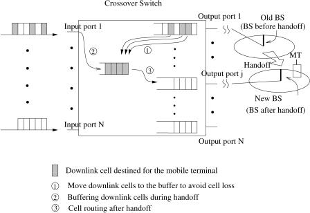
Figure 12.6 illustrates ATM cell flow within a COS. We assume that the original connection path between the mobile terminal and its peer party is routed through input port 1 and output port 1 of the COS. Before handoff occurs, all downlink cells Žshaded cells in the figure. departed from the peer party are multiplexed with other ATM cells and arrive at the input port 1. These downlink cells are routed to output port 1 and transmitted to the mobile terminal via a current base station.
When the mobile terminal moves away from the coverage area of the old base station, handoff is initiated. Here we assume that the new base station is routed from output port j of the COS. Once a signaling message for handoff request is sent from a mobile terminal and a new base station is determined, the ATM network will select a COS. If it is identified as a COS, the switch
Fig. 12.6 Cell routing within a crossover switch.
352 WIRELESS ATM SWITCHES
will start buffering 5 the downlink cells until a new connection subpath is established between the COS and the new base station. After the handoff, all downlink cells, including the buffered cells, will be routed to output port j and transmitted to the mobile terminal through the new base station.
In an ATM switch, all cells arriving at the switch are stored in a switch memory. Their output ports are determined based on their input VCI values. Even though a COS starts buffering newly arriving cells destined for a mobile terminal, the cells for the mobile terminal that are already stored in the switch will be transmitted through the old path.
For example, in Figure 12.6, when the COS starts buffering the newly arriving downlink cells, we can notice that some downlink cells are already stored in the output buffer of port 1. These cells will be lost unless the switch prevents them from being transmitted through output port 1, since they will be transmitted to the previous base station after the mobile terminal leaves the base station.
To avoid this cell loss, a COS has to stop transmitting not only newly arriving downlink cells but also the cells that are already stored in the switch memory Žthe shaded cells in the output buffer of port 1 in Fig. 12.6.. If the COS is an output-buffered ATM switch, to avoid cell loss these cells have to be physically moved to other memory, which will be used for buffering cells during handoff. Moving cells from one buffer to the other also increases the end-to-end delay and wastes memory bandwidth. These buffered cells and physically moved cells from the output buffer will be routed to a different output port Žoutput port j in the example of Fig. 12.6. after a new connection setup is completed between the switch and the new base station. In addition, these cells should be transmitted in sequence.6 To realize these functions with a regular ATM switch is not straightforward, since normal Žnonmobile. ATM traffic does not change its route during the lifetime of a connection.
12.5MOBILITY-SUPPORT ATM SWITCH
While many researchers have proposed handoff schemes to support mobility in wireless ATM networks, there has been little concern about designing a mobility-support ATM switch architecture. Connection path reformation due to handoff requires ATM cell buffering, and this can cause a cell out-of- sequence problem. To solve this problem, a mobility-support ATM switch needs to perform buffering and cell rerouting efficiently, achieve in-sequence cell transmission, and avoid cell loss during handoff w33x.
A COS needs an additional buffer that temporarily stores cells during handoff. It has to stop transmitting all downlink cells Žnewly arriving cells and
5A COS needs an additional buffer for this.
6ATM cell order should be guaranteed in ATM networks, even in a handoff situation, to reduce the resequencing burden in higher layers.
MOBILITY-SUPPORT ATM SWITCH |
353 |
cells already stored in the switch memory. destined for a mobile terminal immediately after it is identified as a COS. This can avoid cell loss during handoff. In addition, a COS is required to guarantee in-sequence cell delivery during handoff.
12.5.1Design of a Mobility-Support Switch
In w33x the authors proposed a mobility-support ATM switch architecture that satisfies all the above requirements. The switch architecture uses a shared memory, which is fully shared by all output ports. Using a shared memory eliminates the need for additional memory for handoff and makes it easy to route cells to the corresponding output port, which can be dynamically changed during the lifetime of a connection due to handoff.
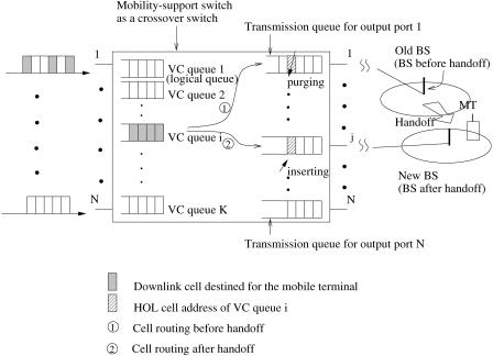
Handoff is based on a VC, and by it the route of the VC is changed. That is, the output port address is changed in the middle of a connection. To efficiently manage each VC, whose output port address can be dynamically changed due to handoff, each connection has its own logical queue ŽVC queue in Fig. 12.7. in the shared memory. A logical queue is used to link all of the backlogged cells of a connection in the order of their arrival times. Cells are stamped with their arrival times when joining their VC queues, and the timestamps are stored together with the cells.
Fig. 12.7 Cell routing in a mobility-support ATM switch.
354 WIRELESS ATM SWITCHES
There will be one transmission queue per output port. Each transmission queue keeps only the addresses of HOL cells7 of VCs that are destined for a corresponding output port. When a cell is transmitted, the address of the next cell in the same VC queue is attached to a transmission queue. All cells’ addresses are sorted according to their arrival times in a transmission queue.
Figure 12.7 illustrates how to manage VC queues in the shared memory and how to route cells before and after handoff. In this example, it is assumed that a virtual connection between a mobile terminal and its peer party was established through input port 1 and output port 1 of the switch. All downlink cells Žshaded cells in the figure. of a virtual connection for the mobile terminal joined the same VC queue. The HOL cell’s address of the VC queue is stored in the transmission queue of output port 1 according to its arrival time. When the HOL cell is transmitted, the address of the next cell in the same VC queue ŽVC queue i in the figure. is extracted and joins the transmission queue in the order of arrival time.
Now we assume that the mobile terminal moves to a new base station and requests handoff to the ATM network. When a signaling message for handoff arrives at the switch, the HOL cell’s address of the corresponding virtual channel is purged from a transmission queue. A newly arriving cell destined for a mobile terminal will still be attached to the corresponding VC queue i, and all cells of the same VC will not be transmitted, since the HOL cell’s address has been deleted from the transmission queue. By doing so, all cells destined for the mobile terminal are buffered immediately after the switch received a handoff signaling message, even though some of the cells had been queued in the switch memory before the message arrived. After a new subpath is established, that is, after the new output port address Žoutput port j in the figure. for the VC is determined, the HOL cell’s address of the same VC is inserted in a corresponding transmission queue. This will restart cell transmission to the mobile terminal through output port j, which is connected to the new base station.
Storing HOL cells’ addresses in transmission queues can prevent cell loss during handoff by purging only a corresponding HOL cell’s address from the transmission queues. Otherwise, the cells for the mobile terminal that were queued in the switch memory before a handoff signaling message will be transmitted to the old base station and be lost Žsince the mobile has already left the base station..
Each transmission queue requires a sorting and purging function for handoff. This function can be realized by an application specific integrated circuits ŽASIC., improved from the existing sequencer chip w34x.
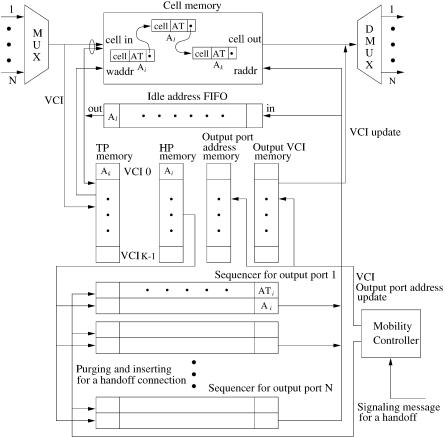
Figure 12.8 depicts the mobility-support switch architecture with a shared memory. It consists of a cell multiplexer, a demultiplexer, sequencer chips Žone for each output port., a mobility controller, an idle-address FIFO, a cell
7 The HOL cell of a backlogged connection is defined as the oldest backlogged cell of the connection.
MOBILITY-SUPPORT ATM SWITCH |
355 |
Fig. 12.8 Mobility-support switch architecture with a shared memory.
memory, and four other small memories8 ŽHP memory, TP memory, output VCI memory, and output port address memory.. The VLSI chip called the sequencer chip replaces a transmission queue in Figure 12.7 and is used for transmission.
Each module of the sequencer contains two types of information associated with each cell. One is the arrival time, AT, of a cell, with which each cell arriving at the switch is time-stamped. The other is the cell’s physical address, A. Each sequencer sorts the ŽAT, A. pairs associated with HOL cells of VC queues destined for the corresponding output port. Each sequencer arranges the ŽAT, A. pair, based on the cell’s arrival time AT, in such a way that smaller AT appears closer to the head of the sequencer. In other words, cells with smaller ATs are scheduled to depart earlier.
8 The number of entries of these memories is the same as the total number of VCIs.
356 WIRELESS ATM SWITCHES
Cells can also be timestamped using a weighted RR or weighted fair queueing algorithm according to the allocation bandwidth to the virtual connections. Thus, it may guarantee the delay bound of each connection Žusing weighted fair queueing., and it only needs to calculate the timestamps when the HOL cells join the transmission queues, instead of assigning time-stamps when they arrive w35x.
All arriving cells from N inputs are first time-division multiplexed and written one by one into the cell memory, each with its timestamp at empty cell locations with the addresses obtained from the idle-address FIFO. The FIFO contains the addresses of current vacant cell locations in the cell memory. Every cell that belongs to the same virtual connection is attached to a logical queue with a forward pointer ŽFP. to point to the next linked cell in the same logical queue. Thus, all of the backlogged cells of a connection are linked in a logical queue in the order of the cells’ arrival times.
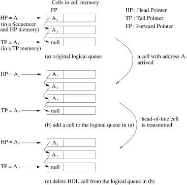
Each logical queue is confined by two pointers, the head pointer ŽHP. and tail pointer ŽTP., which are stored in the HP memory and the TP memory, respectively. The former, which is also stored in a sequencer according to its output port, points to the first cell of a logical queue. The latter, which is stored in the TP memory according to its VCI, points to the last cell. This constructs a linked list and acts as a logical queue for a connection. Note that the HOL cell’s address is stored in both the transmission queue and the HP memory. Therefore, when the HOL cell’s address is purged from the transmission queue due to handoff, it is still kept in the HP memory.
Figure 12.9 shows an example of a logical queue where a cell is leaving or arriving. When a cell arrives, it is stored in the cell memory, and the TP of the associated connection is checked. The TP value stored in the TP memory can be accessed through the cell’s VCI. If the TP is null, the newly arriving cell is a HOL cell, and its ŽAT, A. pair is inserted in a sequencer according to its output port address, which can be obtained from the output port address memory through the cell’s VCI. If the TP is not null, the cell pointed to by the TP w Ak in Fig. 12.9Ža.x is accessed, and its FP is changed from null to the new cell’s address w Al in Fig. 12.9Žb.x. After that, the TP is replaced by the new cell’s address Ž Al .. When a cell is transmitted, the cell’s ŽAT, A. pair is evacuated from its sequencer. If it has its successor, that is, if the cell’s FP is not null, a cell to which the FP points w Aj in Fig. 12.9Žb.x becomes a HOL cell. The new ŽATj , Aj . pair of the HOL cell is inserted in the sequencer. If the departing cell’s FP is null, that is, if the cell is the last cell in a logical queue, the TP of the corresponding entry in the TP memory is updated with a null address. When cells destined for each output port depart from the switch, their addresses are obtained from the rightmost modules of each sequencer, and they are read out from a cell memory one by one for demultiplexing. As soon as each cell is transmitted, its ŽAT, A. pair is purged from the corresponding sequencer and all other ŽAT, A. pairs in the sequencer are shifted to the right by one position. The freed-up locations in the cell memory can be used by future cells, and their addresses are returned to the idle-address FIFO.
MOBILITY-SUPPORT ATM SWITCH |
357 |
Fig. 12.9 Adding and deleting a cell in a logical queue.
Unlike in a normal ATM switch architecture, in the mobility-support switch architecture a cell’s VPIrVCI update is performed when the cell departs from the switch, since the VPIrVCI and output port address can be changed due to handoff while the cell is in the switch memory.
When a signaling message for handoff arrives, the switch stops transmitting ATM cells to an associated output port. This is done through the following operation. When the mobility controller receives the signaling message, it checks the HP memory with the associated VCI. If the HP is null, that means the logical queue of the virtual connection is empty. Then, the corresponding output port address is updated with a null address. When a new cell of the same connection arrives, its ŽAT, A. pair is not inserted in a sequencer, since the associated output port address is updated with a null address and this results in stopping transmission of ATM cells for the handoff connection. If the HP is not null, the address exists in the corresponding sequencer for transmission. This information should be removed from the sequencer to stop transmission. The way to purge the associated ŽAT, A. pair in a sequencer is to broadcast the cell’s address to all modules. If the local address matches the broadcast address, its ŽAT, A. pair will be purged from the Sequencer.
358 WIRELESS ATM SWITCHES
When a signaling message for the completion of the connection setup between the switch and the new base station which a mobile terminal is currently visiting arrives, the handoff controller updates the output port address in the output port address memory and the output VCI in the output VCI memory for the handoff connection. Since the signaling message has information about a new connection subpath for a mobile’s handoff, a COS can resume transmitting ATM cells of a handoff connection with a new allocated output port address and VCI. To resume transmission, the mobility controller accesses the HP memory through the old VCI to find the HOL cell of the handoff connection. If the HP is not null, its ŽAT, A. pair is inserted in a sequencer that is associated with the new output port address. This can resume transmitting cells of the handoff connection through the new output port.
12.5.2Performance
In this subsection we present the performance of the mobility-support switch architecture described in the previous section.
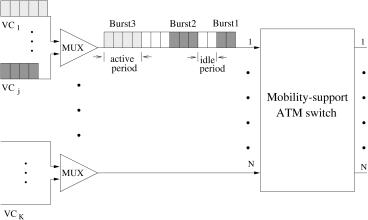
For performance study, it is assumed that cells from different VCs are multiplexed in bursts, and that the bursts are interleaved as they arrive at each input port of the switch. To quantify the traffic characteristics, the following traffic model is considered in which an arrival process to an input port alternates between on Žactive. and off Židle. periods.
Figure 12.10 shows the traffic model used for simulations. During the on period, cells that originate from the same VC arrive at an input port continuously in consecutive cell time slots, and during the off period no cells are generated. Both the on and off periods are assumed to be geometrically distributed with average lengths Ew Bx and Ew I x, respectively.
Fig. 12.10 The simulated traffic model.

MOBILITY-SUPPORT ATM SWITCH |
359 |
Let us define p as the probability that an arriving cell is the last cell in a burst, and q as the probability that a new burst starts per time slot. Then the probability that the burst has i cells is
P w B s i x s Ž1 y p. iy1 p, i G 1, |
Ž12.1. |
and the probability that an idle period will last for j time slots is
P w I s j x s Ž1 y q. j q, j G 0, |
Ž12.2. |
where we assume that there is at least one cell in each burst and the duration of an idle period can be zero. The average lengths Ew Bx and Ew I x are given by
Ew B x s |
1 |
and Ew I x s |
1 y q |
. |
Ž12.3. |
p |
|
||||
|
|
q |
|
||
Given p and q, the offered load is equal to
Ew B x |
. |
Ž12.4. |
|
Ew B x q Ew I x |
|||
|
|
In this simulation study, it is assumed that the switch size N is 16 and the total number of VCs is 512 Ž32 VCs per input port.. The initial route of each VC is shown in Table 12.1. Then the offered load Ž i . of each input port i
TABLE 12.1 Initial Routing Table
|
Input |
Output |
VC |
Port Address |
Port Address |
|
|
|
1 |
1 |
1 |
2 |
1 |
2 |
. |
. |
. |
.. |
.. |
.. |
16 |
1 |
16 |
17 |
1 |
1 |
18 |
1 |
2 |
. |
. |
. |
.. |
.. |
.. |
32 |
1 |
16 |
33 |
2 |
1 |
34 |
2 |
2 |
. |
. |
. |
.. |
.. |
.. |
512 |
16 |
16 |
|
|
|