

Broadband Packet Switching Technologies
.pdf340 WIRELESS ATM SWITCHES
Figure 12.1 illustrates a typical wireless ATM architecture. Fixed wired end user devices and media servers are connected to regular ATM switches. In a mobile wireless ATM environment, the wireless ATM system has a geographical cell structure like traditional cellular systems. The whole coverage area Žindoor or outdoor area. of the wireless ATM system is divided into cells Žmicrocells or picocells.. Each cell has one base station, which is an AP to the wired ATM network. Several base stations are connected to a mobility-support ATM switch. Mobile wireless terminals within a cell communicate with a base station through the wireless medium tor each the ATM network.
12.1.2Wireless ATM Protocol
A wireless ATM system needs to provide seamless support of qualitatively similar multimedia services on both fixed and mobile wireless users. The objective here is to provide mobile wireless users with the full range of services they would enjoy if connected via traditional wired media. To support this wireless ATM feature, a set of new protocols is required. This includes wireless channel-specific protocols such as a MAC protocol and a DLC protocol for error correction. In addition, the mobility feature requires extensions to existing ATM control protocols for handoff, location management, dynamic routing and QoS.
Figure 12.2 shows a wireless ATM reference configuration with related protocol stacks w8x.
In the end user system protocol stack, support for mobility resides both on the user plane and on the control plane. The user plane requires a wireless
Fig. 12.2 Wireless ATM reference configuration and protocol stacks.
WIRELESS ATM SYSTEMS |
341 |
access layer ŽWAL., which includes wireless physical ŽPHY., MAC, and LLC layers. The control plane includes the necessary signaling enhancements as well as the WAL. An APCP is used between the AP and the mobility-support ATM switch. This protocol is needed for the communication of information related to the status of the radio resources from the access point to the switch. The mobility-support ATM switch connected to the access point includes not only APCP but also changes to the UNI, B-ICI, and PNNI ŽUNI q M, B-ICI q M and PNNI q M.. InB-ICI q M, UNI q M, and PNNI q M, qM represents supplemental signaling information to support mobility.
12.2WIRELESS ATM SYSTEMS
12.2.1NEC’s WATMnet Prototype System
The research reported in w1x proposes an ATM cell relay paradigm to be adopted as the basis for the next-generation wireless transport architectures. It is argued that in addition to its regular advantages, the use of ATM switching for intertransmission cell traffic also avoids the crucial problem of developing a new backbone network with sufficient throughput to support intercommunication among the base stations. A protocol layering strategy, harmonized with the standard ATM protocol stack, was proposed. The wireless-specific PHY, MAC, and DLC layers below the ATM layer are added to the standard ATM protocol stack. The baseline ATM network and signaling protocol will have to be augmented to support specific mobilityrelated functions such as address registration, roaming, handoff, and QoS renegotiation in response to the channel impairment. These imply that the regular ATM network layer and control services such as call setup, VCIrVPI addressing, cell prioritization, and flow control indication will continue to be used for the mobile services.
The research presented in w11x describes an experimental wireless ATM network prototype ŽWATMnet. system, which was developed at NEC C & C Research Laboratories in Princeton, NJ. The prototype system operates in the 2.4-GHz industrial, scientific, and medical ŽISM. band at a channel rate of 8 Mbitrs. Wireless network protocols at portable terminal and base station interfaces support available bit rate ŽABR., unspecified bit rate ŽUBR., variable bit rate ŽVBR., and constant bitrate ŽCBR. transport services compatible with ATM, using a dynamic time-division multiple accessrtime division duplex ŽTDMArTDD. MAC protocol for channel sharing and a DLC protocol for error recovery. All network entities, including portable terminals, base stations, and switches, use a mobility-enhanced version of ATM signaling ŽQ.2931 q . for switched virtual circuit ŽSVC. connection control functions, including handoffs.
342 WIRELESS ATM SWITCHES
Hardware and software implementation details are given in w12x for the second version of the WATMnet system operating at 25 Mbitrs in the 5 GHz ISM band. Some experimental results in w13, 14, 15x show the validation of major protocol and software aspects, including DLC, wireless control, and mobility signaling for handoffs.
12.2.2Olivetti’s Radio ATM LAN
The work reported in w4x presents the design issues of a wireless ATM LAN that was developed at Cambridge-Olivetti Research Laboratories. All the base stations operate at 10 Mbitrs, using a quaternary phase-shift keying ŽQPSK. radio at 2.45 GHz Ž10-MHz bandwidth available for short-range data links in buildings in the United Kingdom.. The network uses low-end ATM switches operating at 100 Mbitrs, and has a picocellular structure without frequency reuse. A picocell has a radius of about 10 m.
The Olivetti radio ATM system employs slotted ALOHA with exponential backoff as the MAC layer protocol, which was implemented using Xilinx reprogramable gate arrays. Packets over the wireless link are one ATM cell long, and cell headers are appropriately altered to accommodate QoS, with the VPIrVCI field compressed. A CRC field of 16 bits is used for error detection, and retransmissions Žup to 10. are used for error correction. The next version of this testbed will have a data rate of 25 Mbitrs, operate in the 5-GHz band, and have a range up to 30 m w16x.
12.2.3Virtual Connection Tree
In a paper that deals with topology issues in a cellular radio access network with ATM transport technology, some authors have proposed a structure called the virtual tree architecture w17x. The virtual connection tree totally decentralizes handoff operations, with each mobile responsible for managing its own handoff events without requiring intervention of the admission controller. They showed that this approach can support a very high rate of handoffs between cells. This capability in turn enables very small size cells, therefore very high capacity.
The virtual connection tree consists of ATM switches and cellular base stations connected via some of the ATM switches. The switches are connected via some physical network topology, on top of which is a virtual tree. The root of the tree is a fixed ATM switch node, and the leaves are base stations. When a mobile terminal establishes a connection to the ATM networks, a connection tree is formed from a root Žan ATM switch. to a set of base stations to which a mobile terminal may move. Whenever the mobile terminal moves into one of those base stations, it uses one of the preestablished virtual channels from the root node to the corresponding base station.
The goal of a virtual connection tree is to reduce handoff latency by removing connection setup time for the new connection subpath. However,
WIRELESS ATM SYSTEMS |
343 |
this method uses preestablished multiple virtual channels, which require more bandwidth even though only one of them is used at a time.
12.2.4BAHAMA Wireless ATM LAN
A wireless ATM LAN called BAHAMA was proposed at Bell Laboratories w6x. The basic characteristic of the network is its ad hoc nature. The network is self-organizing, that is, a predetermined topology does not exist. The BAHAMA network consists of two types of network elements: portable base stations ŽPBSs. and mobile endpoints. Each PBS combines ATM switching functionality with wireless access interfaces. The PBSs communicate to determine the network topology after changes due to the addition or deletion of network elements. PBSs are designed with simplicity in mind, and the ATM segmentation and reassembly are carried out in the portable units.
In order to support mobility in the simplest possible way, a new VPIrVCI concept is defined that supports routing based on the destination address. Mobility is supported by means of an adaptive homing algorithm. The advantages of this homing algorithm include preservation of FIFO cell sequence within a connection, and fast handoffs Žachieved by eliminating node-by-node connection setup.. The network employs a wireless data link layer that provides high reliability, based on both automatic repeat request ŽARQ. and forward error correction ŽFEC.. Multiple access is provided by distributed-queuing request update multiple access ŽDQRUMA. w18x.
SWAN is another prototype system proposed at Bell Laboratories w5x. This system is an experimental indoor wireless ATM network based on off-the-shelf 2.4-GHz ISM band radios that operate 625 kbitrs between a base station and a mobile terminal.
12.2.5NTT’s Wireless ATM Access
A system proposed at NTT Wireless System Laboratories called ATM Wireless Access ŽAWA. concentrates on wireless access to an ATM network w2x. It operates in the superhigh-frequency band Ž3 30 GHz. for public and private access at data rate between 30 and 80 Mbitrs. Highly directive antennas help alleviate serious shadowing effects that are apparent at these frequencies. The system is designed as a dual wireless ATM LAN with access to an ATM-based public multimedia network. The AWA system is designed for high-speed access with limited terminal mobility and incorporates dynamic reservation TDMA, FECrARQ, and QPSK modulation with differential detection.
12.2.6Other European Projects
A number of European projects are in the process of developing advanced wireless ATM ŽWATM. demonstrations. Magic WAND ŽWireless ATM Network Demonstration. is a joint European project to build a demonstrator
344 WIRELESS ATM SWITCHES
for multimedia information access using a fast WATM network w19x. The WAND demonstrator operates at up to 25 Mbitrs in the 5-GHz frequency band, and the project is also investigating performance issues related to bit rates exceeding 50 Mbitrs in the 17-GHz frequency band. The overall goal is to design a WATM access network demonstration system that can be commercialized and standardized in the European Telecommunications Standards Institute ŽETSI.. Other European projects include MEDIAN w20x and SAMBA w21x.
12.3RADIO ACCESS LAYERS
A high-speed but low-complexity wireless access technique is critical for providing QoS-based multimedia services to portable terminals. This section outlines wireless-specific protocol layers. These include a radio physical layer, a medium access control ŽMAC. layer, and a data link control ŽDLC. layer.1
12.3.1Radio Physical Layer
WATM requires a high-speed radio technology capable of providing reasonably reliable transmission and reception in the range of 100 500 m. WATM systems may operate in various frequency bands depending on the regulatory policies. Currently, they are usually associated with the recently allocated 5 GHz band in the US and the HIPERLAN w22x band in Europe. The expected operating frequency range is on the order of 20 25 GHz. Typical target bit rates for the radio physical layer of WATM are around 25 Mbitrs, and a modem must be able to support burst operation with relatively short preambles consistent with transmission of short control packets and ATM cells.
The radio physical layer can be divided into the radio physical medium dependent ŽRPMD. and the radio transmission convergence ŽRTC. sub-layers w25x. The RPMD sublayer specifies the lower-level transmission requirements, while the RTC sublayer specifies details of formatted data transmission.
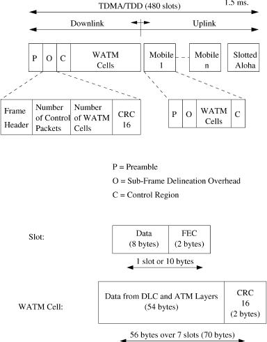
In w12x, the RTC sublayer adopts a dynamic TDMArTDD approach where several virtual circuits are multiplexed in a single radio channel. The TDMArTDD frame structure is shown in Figure 12.3.
The frame consists of 480 slots every 1.5 ms Ž25.6 Mbitrs.. Each slot is formed by 10 bytes, including 8 data bytes and a 2-byte Reed Solomon code wRSŽ10, 8.x for FEC. The frame is divided into an uplink Žmobile to base. and a downlink Žbase to mobile. part. The downlink subframe consists of the
1 In w22x the radio access layers consist of a radio physical layer and a radio DLC layer that contains a MAC sublayer and a logical link control ŽLLC. sublayer.
RADIO ACCESS LAYERS |
345 |
Fig. 12.3 Dynamic TDMArTDD frame structure.
modem preamble ŽP., the subframe delineation overhead ŽO., and the control region ŽC., followed by WATM cells. The preamble is required for TDMA frame delineation and modem synchronization. The frame header in the downlink subframe delineation overhead ŽO. consists of a frame number, a radio port identifier, and reser®ed bytes. The number of control packets ŽC. delineates the control region. Control packets Ž8-byte. are embedded in the TDMArTDD slots. They are used by the MAC and DLC layers. WATM cells Ž56-byte. transport multiplexed downlink user information.
The base station controls the uplink bandwidth allocation for WATM cells from each mobile, taking into account the number and type of active
346 WIRELESS ATM SWITCHES
connections and their bandwidth requirements. Mobiles assemble a subframe similar to that of the base station. The slotted ALOHA region is used by the mobile terminals to send their bandwidth requirements to the base station.
12.3.2Medium Access Control Layer
For efficient sharing of the available wireless bandwidth among multiple mobile users, a radio MAC layer is required. One of the key issues of WATM is the choice of an appropriate MAC protocol, which has to incorporate the wired ATM capability of integrating a variety of traffic types with different QoS requirements. In Figure 12.3, the slotted ALOHA section includes control packets for bandwidth request. The control packet includes the number of requested slots and the request type that is used to identify the ATM traffic types. For CBR traffic, the fixed number of slots is allocated at connection setup time. VBR traffic is constantly adapted, while ABR traffic bandwidth demand is adjusted based on resource management ŽRM. cells. UBR traffic is served in a best-effort manner.
The standardization process of a MAC protocol for WATM is ongoing within the Broadband Radio Access Networks ŽBRAN. project of ETSI. MAC protocols, such as dynamic slot assignment ŽDSAqq. w23x and MASCARA w24x, are currently under investigation as candidates for the ETSI HIPERLAN Type 2 standard, a developing ETSI standard for WATM. These MAC protocols use a combination of contention-based and con- tention-free access on the physical channel and are based on scheduled TDMA.
12.3.3Data Link Control Layer
Link-by-link error control is usually omitted in fixed ATM networks because cell corruption due to channel error is extremely rare for reliable media like copper wire and optical fiber. However, for wireless, bit error rates ŽBERs. up to 10y3 are quite common w26x due to shadowing and other fading effects. To cope with wireless link impairments, a proper error control mechanism is necessary in WATM networks.
A DLC layer is necessary to mitigate the effect of radio channel errors before cells are released to an ATM network layer. Depending on the type of service provided, channel quality, capacity and utilization, the DLC layer may implement a variety of means, including FEC and ARQ.
In w14, 15x, a retransmission-based error control scheme is presented. The proposed error control scheme is applied over a wireless link between a mobile terminal and a base station. The wireless data link control is intended to provide a relatively error-free service to the higher layers by recovering corrupted cells. The error control protocol can be flexibly adapted to different service classes with varying QoS. The recovery mode for each individual virtual circuit can be set independently during its setup time. As an example,
HANDOFF IN WIRELESS ATM |
347 |
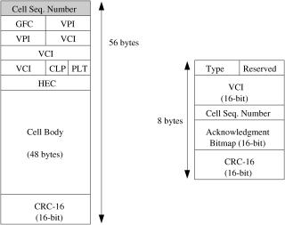
Fig. 12.4 WATM cell format and ACK packet format at DLC layer.
for TCP traffic carried in UBR mode, the error control should be programmed to perform 100% error recovery without worrying about the cell transfer delay over the wireless hop. For CBR voice traffic, on the other hand, the error control attempts to recover a cell only for a specific duration.
Figure 12.4 illustrates WATM cell format and acknowledgment ŽACK. packet format at DLC layer that are used for the error recovery scheme. For error detection and selective cell retransmission, a 1-byte cell sequence number ŽCSN. and a 2 byte CRC are added to the regular 53-byte ATM cell. In the ACK packet format, the 16-bit VCI region specifies the wireless ATM connection for which ACK control packets are generated. The CSN shows the starting control sequence number from which a 16-bit ACK bitmap indicates the reception status of up to 16 transmitted cells.
12.4HANDOFF IN WIRELESS ATM
In a WATM system, a network must provide seamless services to mobile users. The network has to support uninterrupted services to roaming users even though they change their access points to the ATM networks during the lifetime of a connection. This is done through a handoff process w17x. Handoff is the procedure that transfers an ongoing call from one base station Žor access point. to another base station as a user moves through the coverage area. During handoff, connection rerouting and cell buffering are performed in the fixed ATM network. When a mobile user crosses a cell boundary, the original connection path between two end points is broken
348 WIRELESS ATM SWITCHES
and part of it is replaced with a new subpath for continuous support of the ongoing call. Buffering is also necessary for in-sequence and loss-free delivery of the ATM cell containing user data in order to guarantee the QoS on the connection.
12.4.1Connection Rerouting
In a cell-structured WATM system, the radio coverage area of a base station is limited to its cell size. A mobile terminal cannot communicate with a base station if the terminal is beyond its coverage area. To provide seamless service to a mobile user crossing a cell boundary, handoff is needed. When the radio link quality between a mobile terminal and its current base station deteriorates, the mobile terminal has to terminate communication with the base station and communicate with an adjacent base station through a new radio link, which is established by a handoff procedure.
In a fixed ATM network, handoff means connection rerouting during a call. As a result of handoff, the original connection path between two end points is broken, and part of it is replaced with a new subpath for continuous support of the ongoing call.
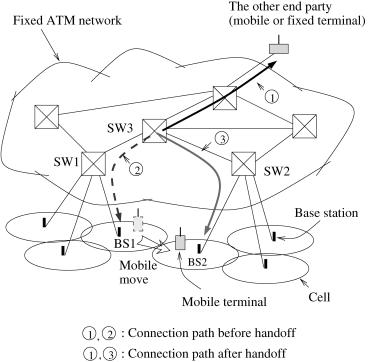
Figure 12.5 shows a typical handoff procedure in a WATM system. Assume that the mobile terminal communicates with the other end party through BS1. When the mobile terminal moves away from BS1 and goes into the cell of BS2, handoff occurs. That is, the mobile terminal switches its access point from BS1 to BS2 and uses the newly established radio link between the mobile and BS2. In the fixed ATM network of the figure, as a result of handoff, the path between SW3 and BS1 is released, and the path between SW3 and BS2 is added to the original connection path.
Virtual channel ŽVC. routes need to be continually modified whenever a mobile terminal switches its network access point during the lifetime of a connection.
One possible rerouting scheme is to rebuild a total end-to-end VC whenever handoff occurs. This introduces large handoff latency. Handoff should be done locally without involving the other end party to reduce this latency.2
Many connection rerouting methods for handoff have been proposed in the literature w6, 17, 27, 28, 29, 30, 31, 32x. Most of them rely on partial connection rerouting.
In w17x, the virtual connection tree concept was proposed. When a mobile terminal establishes a connection to the ATM networks, a connection tree is formed from a root Žan ATM switch. to a set of base stations to which a mobile terminal may move. Whenever the mobile terminal moves into one of
2 Handoff should be performed quickly, since it usually introduces temporary interruption of communication. Due to this service interruption, the QoS may degenerate below an acceptable level.
HANDOFF IN WIRELESS ATM |
349 |
Fig. 12.5 Handoff in a wireless ATM system.
those base stations, it uses one of a set of preestablished virtual channels from the root node to the corresponding base station. The goal of a virtual connection tree is to reduce handoff latency by removing connection setup time for the new connection subpath. However, this method uses preestablished multiple virtual channels, even though only one of them is used at a time. This requires more network resources ŽVC space, bandwidth, and memory for routing information. than other schemes.
The path Žor VC. extension scheme extends an original connection path and adds a new connection subpath from an old base station to a new base station that a mobile terminal is going to visit w28, 29x. This method is simple, and makes it easy to maintain the ATM cell sequence during handoff. However, the extended connection path will increase end-to-end latency, and if base stations and ATM switches have a hierarchical structure as in Figure 12.5, this scheme will produce poor routing efficiency. In addition, a base station needs an ATM switching function to forward ATM cells between base stations.
In the path Žor VC. rerouting scheme of w28, 29x, an original connection path between the mobile’s peer party and an old base station is torn down