

What is a Microcontroller (Paralax, v2.2, student guide, 2004)
.pdfPage 72 · What’s a Microcontroller?
have two pins is because it needs stability. If the pushbutton only had two pins, those pins would eventually bend and break from all the pressure that the pushbutton receives when people press it.
|
|
|
Figure 3-1 |
|
1, 4 |
|
|
Normally Open |
|
1 |
4 |
Pushbutton |
||
|
||||
2, 3 |
2 |
3 |
Schematic symbol (left) |
|
|
|
|
||
|
|
|
and part drawing (right) |
The left side of Figure 3-2 shows how a normally open pushbutton looks when it’s not pressed. When the button is not pressed, there is a gap between the 1,4 and 2,3 terminals. This gap makes it so that the 1,4 terminal can not conduct current to the 2,3 terminal. This is called an open circuit. The name “normally open” means that the pushbutton’s normal state (not pressed) forms an open circuit. When the button is pressed, the gap between the 1,4 and 2,3 terminals is bridged by a conductive metal. This is called closed, and current can flow through the pushbutton.
|
|
|
|
|
|
|
|
Figure 3-2 |
1, 4 |
|
|
|
1, 4 |
|
|
|
Normally Open |
|
|
|
|
|
|
Pushbutton |
||
|
|
|
|
|||||
|
|
|
|
|
|
|
|
|
2, 3 |
|
|
|
2, 3 |
|
|
|
Not pressed (left) and |
|
|
|
|
|||||
|
|
|
|
|
||||
|
|
|
|
|
|
|
|
|
|
|
|
|
|
|
|
|
pressed (right) |
Test Parts for the Pushbutton
(1) LED – pick a color
(1) Resistor - 470 Ω (yellow-violet-brown)
(1) Pushbutton - normally open
(1) Jumper wire
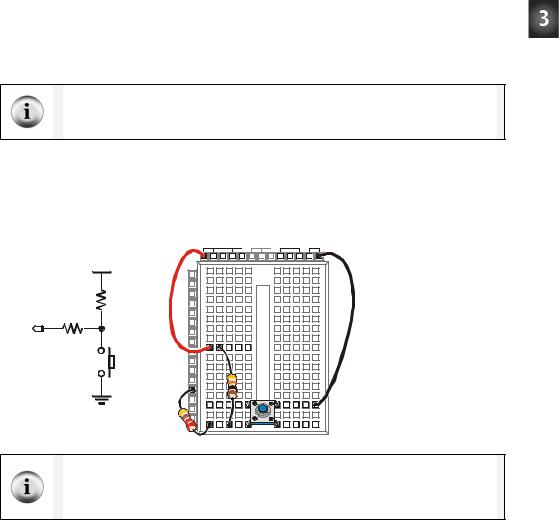
Building the Pushbutton Test Circuit
Figure 3-3 shows a circuit you can build to manually test the pushbutton.
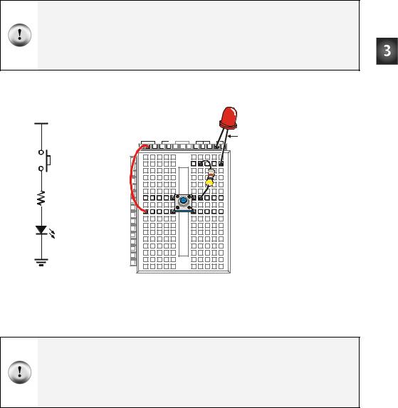
Chapter #3: Digital Input - Pushbuttons · Page 73
Always disconnect power from your Board of Education or BASIC Stamp HomeWork Board before making any changes to your test circuit. From here onward, the instructions will no longer say “Disconnect power…” between each circuit modification. It is up to you to remember to do this.
Always reconnect power to your Board of Education or BASIC Stamp HomeWork Board before downloading a program to the BASIC Stamp.
√Build the circuit shown in Figure 3-3.
Vdd |
|
|
|
|
|
Vdd |
Vin |
Vss |
+ |
1, 4 |
X3 |
|
|
|
P15 |
|
|
|
|
|
|
|
|
|
2, 3 |
P14 |
|
|
|
|
P13 |
|
|
|
|
P12 |
|
|
|
|
P11 |
|
|
|
470 Ω |
P10 |
|
|
|
P9 |
|
|
|
|
|
P8 |
|
|
|
|
P7 |
|
|
|
|
P6 |
|
|
|
LED |
P5 |
|
|
|
P4 |
|
|
|
|
|
P3 |
|
|
|
|
P2 |
|
|
|
|
P1 |
|
|
|
Vss |
P0 |
|
|
|
X2 |
|
|
|
Figure 3-3
Pushbutton Test Circuit
Testing the Pushbutton
When the pushbutton is not pressed, the LED will be off. If the wiring is correct, when the pushbutton is pressed, the LED should be on (emitting light).
Warning signs: If the Pwr LED on the Board of Education flickers, goes dim, or goes out completely when you plug the power supply back in, it means you have a short circuit. If this happens to you, disconnect power immediately and find and correct the mistake in your circuit.
The Power LED on the HomeWork Board is different. It glows only while a program is running. If a program ends (using the END command), the Power LED will also turn off.
√Verify that the LED in your test circuit is off.
Page 74 · What’s a Microcontroller?
√Press and hold the pushbutton, and verify that the LED emits light while you are holding the pushbutton down.
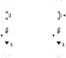
How the Pushbutton Circuit Works
The left side of Figure 3-4 shows what happens when the pushbutton is not pressed. The LED circuit is not connected to Vdd. It is an open circuit that cannot conduct current. By pressing the pushbutton, you close the connection between the terminals with conductive metal making a pathway for electrons to flow through the circuit.
|
|
Vdd |
|
|
Vdd |
|
|
|
|||||||||||||||
|
1, 4 |
|
|
|
|
|
|
|
1, 4 |
|
|
|
|
|
|
|
|
|
|
|
Figure 3-4 |
||
|
|
|
|
|
|
|
|
|
|
|
|||||||||||||
|
|
|
|
|
|
|
|
||||||||||||||||
|
2, 3 |
|
|
|
|
|
|
|
2, 3 |
|
|
|
|
|
|
|
|
|
|
|
|||
|
|
|
|
|
|
|
|
|
|
|
|
|
|
|
|
|
|
|
|||||
|
|
|
|
|
|
|
|
|
|
|
|
|
|
|
|
|
|
|
Pushbutton Not |
||||
|
|
|
|
|
|
|
|
||||||||||||||||
|
|
|
|
|
|
|
|
|
|
|
|||||||||||||
|
|
|
|
|
|
|
|
|
|
|
|
|
|
|
|
|
|
|
|
|
|
|
Pressed, and |
No |
|
|
|
|
|
|
|
|
Ω |
|
|
|
|
|
|
|
|
|
|
|
470 Ω |
Pressed |
|
|
|
|
|
|
|
|
|
|
|
|
|
|
|
|
|
|
|
|
|||||
|
470 |
Current |
|
|
|
|
|
|
|
|
|
|
|||||||||||
|
|
|
|
|
|
|
|
|
|
|
|
||||||||||||
Current |
|
|
Pushbutton circuit |
||||||||||||||||||||
|
|
|
|
|
|
|
|
|
|
|
|
|
|
|
|
|
|
|
|
|
|
||
|
|
|
|
|
|
|
|
|
|
|
|
|
|
|
|
|
|
|
|
|
|
|
|
|
|
|
|
|
|
|
|
|
|
|
|
|
|
|
|
|
|
|
|
|
|
|
open (left) and |
|
|
|
|
|
|
|
|
LED |
|
|
|
|
|
|
|
|
|
|
|
LED |
closed (right) |
||
|
|
|
|
|
|
|
|
|
|
|
|
|
|
|
|
|
|
|
|||||
|
|
|
|
|
|
|
|
|
|
|
|
|
|
|
|
|
|
|
|
|
|
|
|
|
|
|
|
|
|
|
|
|
|
|
|
|
|
|
|
|
|
|
|
|
|
|
|
|
|
|
|
|
|
|
|
|
|
|
|
|
|
|
|
|
|
|
|
|
|
|
|
|
|
Vss |
|
|
|
Vss |
|
|
|
||||||||||||||
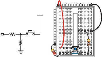
Your Turn – A Short-Circuit
Figure 3-5 shows a different circuit that will cause the LED to behave differently. When the button is not pressed, the LED stays on. When the button is pressed, the LED turns off. The reason the LED turns off when the pushbutton is pressed is because current always follows the path of least resistance. When the pushbutton is pressed, terminals 1,4 and 2,3, have almost no resistance between them, so all the current passes through the pushbutton (short circuit) instead of the LED.
√Build the circuit shown in Figure 3-5.
√Repeat the tests you performed on the first pushbutton circuit you built with this new circuit.

|
|
Chapter #3: Digital Input - Pushbuttons |
· Page 75 |
||
Vdd |
Vdd |
Vin |
Vss |
|
|
|
X3 |
|
|
|
|
1, 4 |
P15 |
|
|
|
|
P14 |
|
|
|
|
|
|
P13 |
|
|
|
|
|
P12 |
|
+ |
Figure 3-5 |
|
LED |
P11 |
|
|
||
P10 |
|
|
LED that Gets |
|
|
|
P9 |
|
|
Shorted by |
|
2, 3 |
P8 |
|
|
|
|
|
|
Pushbutton |
|
||
|
P7 |
|
|
|
|
|
P6 |
|
|
|
|
470 Ω |
P5 |
|
|
|
|
P4 |
|
|
|
|
|
|
P3 |
|
|
|
|
|
P2 |
|
|
|
|
|
P1 |
|
|
|
|
Vss |
P0 |
|
|
|
|
X2 |
|
|
|
|
|
Can you really do that with the LED? Up until now, the LED’s cathode has always been connected to Vss. Now, the LED is in a different place in the circuit, with its anode connected to Vdd. People often ask if this breaks any circuit rules, and the answer is no. The electrical pressure supplied by Vdd and Vss is 5 volts. The diode will always use 1.6 volts, and the resistor will always use 3.4 volts, regardless of their order.
ACTIVITY #2: READING A PUSHBUTTON WITH THE BASIC STAMP
In this activity, you will connect a pushbutton circuit to the BASIC Stamp and display whether or not the pushbutton is pressed. You will do this by writing a PBASIC program that checks the state of the pushbutton and displays it in the Debug Terminal.
Parts for a Pushbutton Circuit
(1) Pushbutton - normally open
(1) Resistor – 220 Ω (red-red-brown)
(1)Resistor – 10 kΩ (brown-black-orange)
(2)Jumper wires
Building a Pushbutton Circuit for the BASIC Stamp
Figure 3-6 shows a pushbutton circuit that is connected to BASIC Stamp I/O pin P3.
√Build the circuit shown in Figure 3-6.
Page 76 · What’s a Microcontroller? |
|
|
|
|
|
Vdd |
Vin |
Vss |
Figure 3-6 |
|
X3 |
|
|
Pushbutton Circuit |
|
P15 |
|
|
Connected to I/O Pin |
Vdd |
|
|
P3 |
|
P14 |
|
|
||
|
P13 |
|
|
|
|
P12 |
|
|
On the wiring |
|
P11 |
|
|
|
|
P10 |
|
|
diagram, the 220 Ω |
|
P9 |
|
|
resistor is on the left |
|
P8 |
|
|
|
P3 |
P7 |
|
|
side connecting the |
P6 |
|
|
pushbutton to P3 |
|
220 Ω |
P5 |
|
|
|
|
|
while the 10 kΩ |
||
P4 |
|
|
||
10 kΩ |
P3 |
|
|
resistor is on the |
|
P2 |
|
|
right, connecting the |
|
P1 |
|
|
|
Vss |
P0 |
|
|
pushbutton circuit to |
X2 |
|
|
Vss. |
|
|
|
|
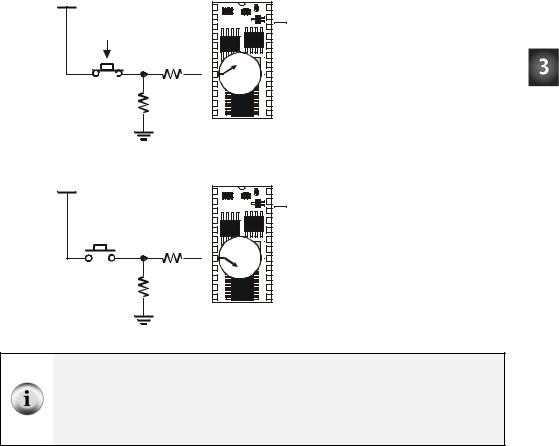
|
Figure 3-7 shows what the BASIC Stamp sees when the button is pressed, and when it’s not pressed. When the pushbutton is pressed, the BASIC Stamp senses that Vdd is connected to P3. Inside the BASIC Stamp, this causes it to place the number 1 in a part of its memory that stores information about its I/O pins. When the pushbutton is not pressed, the BASIC Stamp cannot sense Vdd, but it can sense Vss through the 10 kΩ and 220 Ω resistors. This causes it to store the number 0 in that same memory location that stored a 1 when the pushbutton was pressed.
Chapter #3: Digital Input - Pushbuttons · Page 77
Vdd |
|
SOUT |
1 |
|
24 |
VIN |
|
|
|
||||
|
|
SIN |
2 |
BS2 |
23 |
VSS |
|
|
ATN |
3 |
|
22 |
RES |
|
|
VSS |
4 |
|
21 |
VDD (+5V) |
|
|
P0 |
5 |
|
20 |
P15 |
|
|
P1 |
6 |
|
19 |
P14 |
|
|
P2 |
7 |
1 |
18 |
P13 |
|
|
P3 |
8 |
0 |
17 |
P12 |
|
220 Ω |
P4 |
9 |
16 |
P11 |
|
10 kΩ |
P5 10 |
|
15 |
P10 |
||
|
P6 11 |
|
14 |
P9 |
||
|
|
P7 |
12 |
|
13 |
P8 |
|
|
|
|
BS2-IC |
|
|
|
Vss |
|
|
|
|
|
Vdd |
|
SOUT |
1 |
|
24 |
VIN |
|
|
|
||||
|
|
SIN |
2 |
BS2 |
23 |
VSS |
|
|
ATN |
3 |
|
22 |
RES |
|
|
VSS |
4 |
|
21 |
VDD (+5V) |
|
|
P0 |
5 |
|
20 |
P15 |
|
|
P1 |
6 |
|
19 |
P14 |
|
|
P2 |
7 |
1 |
18 |
P13 |
|
|
P3 |
8 |
0 |
17 |
P12 |
|
220 Ω |
P4 |
9 |
16 |
P11 |
|
10 kΩ |
P5 10 |
|
15 |
P10 |
||
|
P6 11 |
|
14 |
P9 |
||
|
|
P7 |
12 |
|
13 |
P8 |
|
|
|
|
BS2-IC |
|
|
Figure 3-7
BASIC Stamp Reading
a Pushbutton
When the pushbutton is pressed, the BASIC Stamp reads a 1 (above). When the pushbutton is not pressed, the BASIC Stamp reads a 0 (below).
Vss
Binary and Circuits: The base-2 number system uses only the digits 1 and 0 to make numbers, and these binary values can be transmitted from one device to another. The BASIC Stamp interprets Vdd (5 V) as binary-1 and Vss (0 V) as binary-0. Likewise, when the BASIC Stamp sets an I/O pin to Vdd using HIGH, it sends a binary-1. When it sets an I/O pin to Vss using LOW, it sends a binary-0. This is a very common way of communicating binary numbers used by many computer chips and other devices.
Programming the BASIC Stamp to Monitor the Pushbutton
The BASIC Stamp stores the one or zero it senses at I/O pin P3 in a memory location called IN3. Here is an example program that shows how this works:
Example Program: ReadPushbuttonState.bs2
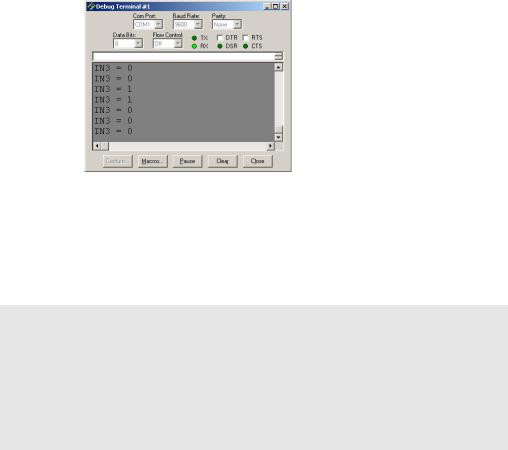
This program makes the BASIC Stamp check the pushbutton every ¼ second and send the value of IN3 to the Debug Terminal. Figure 3-8 shows the Debug Terminal while the program is running. When the pushbutton is pressed, the Debug Terminal displays
Page 78 · What’s a Microcontroller?
the number 1, and when the pushbutton is not pressed, the Debug Terminal displays the number 0.
Figure 3-8
Debug Terminal
Displaying
Pushbutton States
The Debug Terminal displays 1 when the pushbutton is pressed and 0 when it is not pressed.
√Enter the ReadPushbuttonState.bs2 program into the BASIC Stamp Editor.
√Run the program.
√Verify that the Debug Terminal displays the value 0 when the pushbutton is not pressed.
√Verify that the Debug Terminal displays the value 1 when the pushbutton is pressed and held.
'What's a Microcontroller - ReadPushbuttonState.bs2
'Check and send pushbutton state to Debug Terminal every 1/4 second.
'{$STAMP BS2}
'{$PBASIC 2.5}
DO
DEBUG ? IN3
PAUSE 250
LOOP
How ReadPushbuttonState.bs2 Works
The DO…LOOP in the program repeats every ¼ second because of the command PAUSE 250. Each time through the DO…LOOP, the command DEBUG ? IN3 sends the value of IN3 to the Debug Terminal. The value of IN3 is the state that I/O pin P3 senses at the instant the DEBUG command is executed.
Chapter #3: Digital Input - Pushbuttons · Page 79
Your Turn – A Pushbutton with a Pull-up Resistor
The circuit you just finished working with has a resistor connected to Vss. This resistor is called a pull-down resistor because it pulls the voltage at P3 down to Vss (0 volts) when the button is not pressed. Figure 3-9 shows a pushbutton circuit that uses a pull-up resistor. This resistor pulls the voltage up to Vdd (5 volts) when the button is not pressed. The rules are now reversed. When the button is not pressed, IN3 stores the number 1, and when the button is pressed, IN3 stores the number 0.
The 220 Ω resistor is used in the pushbutton example circuits to protect the BASIC Stamp I/O pin. Although it’s a good practice for prototyping, in most products, this resistor is replaced with a wire (since wires cost less than resistors).
√Modify your circuit as shown in Figure 3-9.
√Re-run ReadPushbuttonState.bs2.
√Using the Debug Terminal, verify that IN3 is 1 when the button is not pressed and 0 when the button is pressed.
Vdd Vin Vss
Vdd |
X3 |
|
P15 |
||
|
||
|
P14 |
|
10 kΩ |
P13 |
|
P12 |
||
|
P11 |
|
P3 |
P10 |
|
P9 |
||
220 Ω |
P8 |
|
P7 |
||
|
P6 |
|
|
P5 |
|
|
P4 |
|
|
P3 |
|
Vss |
P2 |
|
P1 |
||
|
P0 |
|
|
X2 |
Figure 3-9
Modified Pushbutton
Circuit
Active-low vs. Active-high: This pushbutton Figure 3-9 is called active-low because it sends the BASIC Stamp a low signal (Vss) when the button is active (pressed). The pushbutton circuit in Figure 3-6 the main activity is active-high because it sends a high signal (Vdd) when the button is active (pressed).
Page 80 · What’s a Microcontroller?
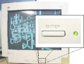
ACTIVITY #3: PUSHBUTTON CONTROL OF AN LED CIRCUIT
Figure 3-10 shows a zoomed in view of a pushbutton and LED used to adjust the settings on a computer monitor. This is just one of many devices that have a pushbutton that you can press to adjust the device and an LED to show you the device’s status.
Figure 3-10
Button and LED on a Computer Monitor
The BASIC Stamp can be programmed to make decisions based on what it senses. For example, it can be programmed to decide to flash the LED on/off ten times per second when the button is pressed.
Pushbutton and LED Circuit Parts
(1) Pushbutton – normally open
(1) Resistor - 10 kΩ (brown-black-orange)
(1) LED – any color
(1) Resistor – 220 Ω (red-red-brown)
(1)Resistor – 470 Ω (yellow-violet-brown)
(2)Jumper wires
Building the Pushbutton and LED Circuits
Figure 3-11 shows the pushbutton circuit used in the activity you just finished along with the LED circuit used in Chapter #2, Activity #2.
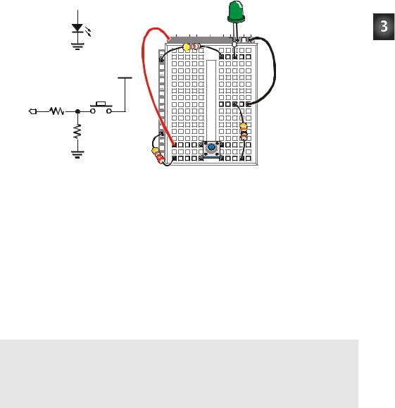
Chapter #3: Digital Input - Pushbuttons · Page 81
√Build the circuit shown in Figure 3-11.
P14 


 470 Ω
470 Ω
LED |
Vdd |
Vin |
Vss |
X3


 +
+
Vss |
P15 |
|
|
P14 |
|
Vdd |
P13 |
|
P12 |
||
|
P11 |
|
|
P10 |
|
|
P9 |
|
|
P8 |
|
P3 |
P7 |
|
P6 |
||
220 Ω |
P5 |
|
P4 |
||
10 kΩ |
||
P3 |
||
|
P2 |
|
|
P1 |
|
Vss |
P0 |
|
X2 |
Figure 3-11
Pushbutton and
LED Circuit
Programming Pushbutton Control
The BASIC Stamp can be programmed to make decisions using an IF…THEN…ELSE statement. The example program you are about to run will flash the LED on and off when the pushbutton is pressed using an IF…THEN…ELSE statement. Each time through the DO…LOOP, the IF…THEN…ELSE statement checks the state of the pushbutton and decides whether or not to flash the LED.
Example Program: PushbuttonControlledLed.bs2
√Enter PushbuttonControlledLed.bs2 into the BASIC Stamp Editor and run it.
√Verify that the LED flashes on and off while the pushbutton is pressed and held down.
√Verify that the LED does not flash when the pushbutton is not pressed down.
'What's a Microcontroller - PushbuttonControlledLed.bs2
'Check pushbutton state 10 times per second and blink LED when pressed.
'{$STAMP BS2}
'{$PBASIC 2.5}
DO