

What is a Microcontroller (Paralax, v2.2, student guide, 2004)
.pdfPage 52 · What’s a Microcontroller?
persistence of vision. Here is how to test to see what your persistence of vision threshold is:
√Try modifying both of your PAUSE command’s Duration arguments so that they are 100.
√Re-run your program and check for flicker.
√Reduce both Duration arguments by 5 and try again.
√Keep reducing the Duration arguments until the LED appears to be on all the time with no flicker. It will be dimmer than normal, but it should not appear to flicker.
One last thing to try is to create a one-shot LED flasher. When the program runs, the LED flashes only once. This is a way to look at the functionality of the DO…LOOP. You can temporarily remove the DO…LOOP from the program by placing an apostrophe to the left of both the DO and LOOP keywords as shown below.
'DO
HIGH 14 PAUSE 1000 LOW 14 PAUSE 2000
'LOOP
√Modify and re-run the program using the code snippet above.
√Explain what happened, why did the LED only flash once?
Commenting a line of code: Placing an apostrophe to the left of a command changes it into a comment. This is a useful tool because you don’t actually have to delete the command to see what happens if you remove it from the program. It is much easier to add and remove an apostrophe than it is to delete and re-type the commands.
ACTIVITY #3: COUNTING AND REPEATING
In the previous activity, the LED circuit either flashed on and off all the time, or it flashed once and then stopped. What if you only want the LED to flash on and off ten times? Computers (including the BASIC Stamp) are great at keeping running totals of how many times something happens. Computers can also be programmed to make

Chapter #2: Lights On – Lights Off · Page 53
decisions based on a variety of conditions. In this activity, you will program the BASIC Stamp to stop flashing the LED on and off after ten repetitions.
Counting Parts and Test Circuit
Use the example circuit shown in Figure 2-11 on page 48.
How Many Times?
There are many ways to make the LED blink on and off ten times. The simplest way is to use a FOR…NEXT loop. The FOR…NEXT loop is similar to the DO…LOOP. Although either loop can be used to repeat commands a fixed number of times, FOR…NEXT is easier to use.
The FOR…NEXT loop depends on a variable to track how many times the LED has blinked on and off. A variable is a word of your choosing that is used to store a value. The next example program uses the word counter to ‘count’ how many times the LED has been turned on and off.
Picking words for variable names has several rules:
1.The name cannot be a word that is already used by PBASIC. These words are called reserved words, and some examples that you should already be familiar with are: DEBUG, PAUSE, HIGH, LOW, DO, and LOOP.
2.The name cannot contain a space.
3.Even though the name can contain letters, numbers, or underscores, it must begin with a character.
4.The name must be less than 33 characters long.
Example Program: LedOnOffTenTimes.bs2
The program LedOnOffTenTimes.bs2 demonstrates how to use a FOR…NEXT loop to blink an LED on and off ten times.
√Your test circuit from Activity #2 should be built (or rebuilt) and ready to use.
√Enter the LedOnOffTenTimes.bs2 code into the BASIC Stamp Editor.
√Connect power to your Board of Education or HomeWork Board.
√Run the program.
√Verify that the LED flashes on and off ten times.

Page 54 · What’s a Microcontroller?
√Run the program a second time, and verify that the value of counter shown in the Debug Terminal accurately tracks how many times the LED blinked. Hint: instead of clicking Run a second time, you can press and release the Reset button on your Board of Education or HomeWork Board.
'What's a Microcontroller - LedOnOffTenTimes.bs2
'Turn an LED on and off. Repeat 10 times.
'{$STAMP BS2}
'{$PBASIC 2.5}
counter VAR Byte
FOR counter = 1 TO 10
DEBUG ? counter
HIGH 14
PAUSE 500
LOW 14
PAUSE 500
NEXT
DEBUG "All done!"
END
How LedOnOffTenTimes.bs2 Works
This PBASIC statement
counter VAR Byte
tells the BASIC Stamp Editor that your program will use the word counter as a variable that can store a byte’s worth of information.

Chapter #2: Lights On – Lights Off · Page 55
What’s a Byte? A byte is enough memory to store a number between 0 and 255. The BASIC Stamp has four different types of variables, and each can store a different range of numbers:
Table 2-2: Variable Types and Values They Can Store
Variable type |
Range of Values |
|
|
Bit |
0 to 1 |
Nib |
0 to 15 |
Byte |
0 to 255 |
Word |
0 to 65535 |
|
|
The question mark formatter before a variable in a DEBUG command tells the Debug Terminal to display the name of the variable and its value. This is how the command
DEBUG ? counter
displays both the name and the value of the counter variable in the Debug Terminal.
The FOR…NEXT loop and all the commands inside it are shown below. The statement FOR counter = 1 to 10 tells the BASIC Stamp that it will have to set the counter variable to 1, then keep executing commands until it gets to the NEXT statement. When the BASIC Stamp gets to the NEXT statement, it jumps back to the FOR statement. The FOR statement adds one to the value of counter. Then, it checks to see if counter is greater than ten yet. If not, it repeats the process. When the value of counter finally reaches eleven, the program skips the commands between the FOR and NEXT statements and moves on to the command that comes after the NEXT statement.
FOR counter = 1 to 10
DEBUG ? counter, CR
HIGH 14
PAUSE 500
LOW 14
PAUSE 500
NEXT
The command that comes after the NEXT statement is:
Page 56 · What’s a Microcontroller?
DEBUG "All done!"
This command is included just to show what the program does after ten times through the FOR…NEXT loop. It moves on to the command that comes after the NEXT statement.
Your Turn – Other Ways to Count
√Replace the statement
FOR counter = 1 to 10 |
with this: |
FOR counter = 1 to 20 |
in LedOnOffTenTimes.bs2 and re-run the program. What did the program do differently, and was this expected?
√Try a second modification to the FOR statement. This time, change it to
FOR counter = 20 to 120 STEP 10
How many times did the LED flash? What values displayed in the Debug Terminal?
ACTIVITY #4: BUILDING AND TESTING A SECOND LED CIRCUIT
Indicator LEDs can be used to tell the machine’s user many things. Many devices need two, three, or more LEDs to tell the user if the machine is ready or not, if there is a malfunction, if it’s done with a task, and so on.
In this activity, you will repeat the LED circuit test in Activity #1 for a second LED circuit. Then you will adjust the example program from Activity #2 to make sure the LED circuit is properly connected to the BASIC Stamp. After that, you will modify the example program from Activity #2 to make the LEDs operate in tandem.
Extra Parts
In addition to the parts you used in Activities 1 and 2, you will need these parts:
(1) LED - yellow
(1) Resistor – 470 Ω (yellow-violet-brown)

Chapter #2: Lights On – Lights Off · Page 57
Building and Testing the Second LED Circuit
In Activity #1, you manually tested the first LED circuit to make sure it worked before connecting it to the BASIC Stamp. Before connecting the second LED circuit to the BASIC Stamp, it’s important to test it too.
√Disconnect power from your Board of Education or HomeWork Board.
√Construct the second LED circuit as shown in Figure 2-13.
√Reconnect power to your Board of Education or HomeWork Board.
√Did the LED circuit you just added turn on? If yes, then continue. If no, Activity #1 has some trouble-shooting suggestions that you can repeat for this circuit.
|
Vdd |
|
470 Ω |
P14 |
|
470 Ω |
|
|
LED |
|
LED |
Vss |
Vss |
Vdd |
Vin |
Vss |
X3 |
|
+ |
|
+ |
|
P15 |
|
|
|
|
|
P14 |
|
Figure 2-13 |
P13 |
|
|
P12 |
|
Manual Test |
P11 |
|
|
P10 |
|
Circuit for |
P9 |
|
Second LED |
P8 |
|
|
P7 |
|
|
P6 |
|
|
P5 |
|
|
P4 |
|
|
P3 |
|
|
P2 |
|
|
P1 |
|
|
P0 |
|
|
X2
√Disconnect power to your Board of Education or HomeWork Board.
√Modify the second LED circuit you just tested by connecting the LED circuit’s resistor lead (input) to P15 as shown in Figure 2-14.
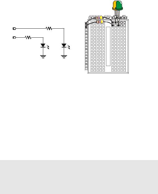
Page 58 · What’s a Microcontroller?
|
|
Vdd |
Vin |
Vss |
Figure 2-14 |
|
|
X3 |
|
+ |
Connecting |
|
|
P15 |
|
+ |
the Second |
|
|
|
|
||
|
|
|
|
LED to the |
|
P15 |
|
P14 |
|
|
|
|
P13 |
|
|
BASIC |
|
|
|
|
|
||
470 Ω |
|
P12 |
|
|
Stamp |
|
P11 |
|
|
||
P14 |
|
P10 |
|
|
|
470 Ω |
|
P9 |
|
|
Schematic |
|
P8 |
|
|
||
|
|
P7 |
|
|
(left) and |
LED |
LED |
P5P6 |
|
|
wiring |
Vss |
Vss |
P4 |
|
|
diagram |
P3 |
|
|
(right). |
||
|
|
P2 |
|
|
|
|
|
P1 |
|
|
|
|
|
P0 |
|
|
|
|
|
X2 |
|
|
|
Using a Program to Test the Second LED Circuit
In Activity #2, you used an example program and the HIGH and LOW commands to control the LED circuit connected to P14. These commands will have to be modified to control the LED circuit connected to P15. Instead of using HIGH 14 and LOW 14, you will use
HIGH 15 and LOW 15.
Example Program: TestSecondLed.bs2
√Enter TestSecondLed.bs2 into the BASIC Stamp Editor.
√Connect power to your Board of Education or HomeWork Board.
√Run TestSecondLED.bs2.
√Make sure the LED circuit connected to P15 is flashing. If the LED connected to P15 flashes, move on to the next example (Controlling Both LEDs). If the LED circuit connected to P15 is not flashing, check your circuit for wiring errors and your program for typing errors and try again.
'What's a Microcontroller - TestSecondLed.bs2
'Turn LED connected to P15 on and off.
'Repeat 1 time per second indefinitely.
'{$STAMP BS2}
'{$PBASIC 2.5}
DEBUG "Program Running!"

Chapter #2: Lights On – Lights Off · Page 59
DO
HIGH 15
PAUSE 500
LOW 15
PAUSE 500
LOOP
Controlling Both LEDs
Yes, you can flash both LEDs at once. One way you can do this is to use two HIGH commands before the first PAUSE command. One HIGH command sets P14 high, and the next HIGH command sets P15 high. You will also need two LOW commands to turn both LEDs off. It’s true that both LEDs will not turn on and off at exactly the same time because one is turned on or off after the other. However, there is no more than a millisecond’s difference between the two changes, and the human eye will not detect it.
Example Program: FlashBothLeds.bs2
√Enter the FlashBothLeds.bs2 code into the BASIC Stamp Editor.
√Run the program.
√Verify that both LEDs appear to flash on and off at the same time.
'What's a Microcontroller - FlashBothLeds.bs2
'Turn LEDs connected to P14 and P15 on and off.
'{$STAMP BS2}
'{$PBASIC 2.5}
DEBUG "Program Running!"
DO
HIGH 14
HIGH 15
PAUSE 500
LOW 14
LOW 15
PAUSE 500
LOOP
Page 60 · What’s a Microcontroller?
Your Turn – Alternate LEDs
You can cause the LEDs to alternate by swapping the HIGH and LOW commands that control one of the I/O pins. This means that while one LED is on, the other will be off.
√Modify FlashBothLeds.bs2 so that the commands between the DO and LOOP keywords look like this:
HIGH 14
LOW 15
PAUSE 500
LOW 14
HIGH 15
PAUSE 500
√Run the modified version of FlashBothLeds.bs2 and verify that the LEDs flash alternately on and off.
ACTIVITY #5: USING CURRENT DIRECTION TO CONTROL A BI-COLOR LED
The device shown in Figure 2-15 is a security monitor for electronic keys. When an electronic key with the right code is used, the LED changes color, and a door opens. This kind of LED is called a bi-color LED. This activity answers two questions:
1.How does the LED change color?
2.How can you run one with the BASIC Stamp?

Chapter #2: Lights On – Lights Off · Page 61
Figure 2-15
Bi-color LED in a
Security Device
When the door is locked, this bi-color LED glows red. When the door is unlocked by an electronic key with the right code, the LED turns green.
Introducing the Bi-Color LED
The bi-color LED’s schematic symbol and part drawing are shown in Figure 2-16.
1
|
|
Figure 2-16 |
|
LED- |
Bi-color LED |
Red |
Green bicolor |
Schematic symbol (left) |
|
1 2 |
|
|
2 |
and part drawing (right). |
|
|
The bi-color LED is really just two LEDs in one package. Figure 2-17 shows how you can apply voltage in one direction and the LED will glow red. By disconnecting the LED and plugging it back in reversed, the LED will then glow green. As with the other LEDs, if you connect both terminals of the circuit to Vss, the LED will not emit light.