

568 |
Chapter 16 |
16.4 Sample Programs
The following sections contain the sample programs discussed in this chapter.
16.4.1 ADF84 Program
;File name: ADCF84.asm
;Last Update: June 8, 2006
;Author: Julio Sanchez
;Processor: 16F84A
;Description:
;Program to demonstrate use of the ADC0831 Analog to
;Digital converter with the 16F84 PIC. Program reads the
;value of a potentionmeter connected to Port-A, line 0
;and displays resistance in the range 0 to 255 on the
;attached LCD.
;Circuit:
; |
ADC0831 |
16F84 |
CIRCUIT |
; PIN LINE
;6 DO ------------- RB0
;7 CLK ------------- RB1
;1 CS ------------- RB2
;2 Vin+ ------------------------------ POT2
;3 Vin- ------------------------------ GND
;5 Vref ------------------------------ +5v
;8 Vcc ------------------------------ +5v
;For LCD display parameters see the LCDTest2 program.
;WARNING:
;Code assumes 4Mhz clock. Delay routines must be
;edited for faster clock
;
;===========================
;switches ;===========================
;Switches used in __config directive:
; |
|
_CP_ON |
Code protection ON/OFF |
; * |
_CP_OFF |
|
|
; |
* |
_PWRTE_ON |
Power-up timer ON/OFF |
;_PWRTE_OFF
; |
_WDT_ON |
Watchdog timer ON/OFF |
|
|
; * _WDT_OFF |
|
|
|
|
; |
_LP_OSC |
Low power crystal |
oscillator |
|
; * _XT_OSC |
External parallel |
resonator/crystal oscillator |
||
; |
_HS_OSC |
High speed crystal resonator (8 to |
10 MHz) |
|
; |
|
Resonator: Murate |
Erie CSA8.00MG = |
8 MHz |
; |
_RC_OSC |
Resistor/capacitor oscillator |
|
|
Analog to Digital and Realtime Clocks |
569 |
|
; | |
(simplest, 20% error) |
|
;|
;|_____ * indicates setup values presently selected
;========================= ; setup and configuration ;=========================
processor |
16f84A |
include |
<p16f84A.inc> |
__config |
_XT_OSC & _WDT_OFF & _PWRTE_ON & _CP_OFF |
errorlevel -302
; Suppress bank-related warning
;============================================================
; M A C R O S
;============================================================ ; Macros to select the register banks in 16F84
Bank0 |
MACRO |
|
; Select RAM bank 0 |
|
bcf |
STATUS,RP0 |
|
|
ENDM |
|
|
Bank1 |
MACRO |
|
; Select RAM bank 1 |
|
bsf |
STATUS,RP0 |
|
|
ENDM |
|
|
;===================================================== |
|||
; |
|
|
constant definitions |
; for PIC-to-LCD pin wiring and LCD line addresses |
|||
;===================================================== |
|||
#define E_line 1 |
|
;| |
|
#define RS_line 2 |
|
;| — from circuit wiring diagram |
|
#define RW_line 3 |
|
;| |
|
; LCD line addresses (from LCD data sheet) |
|||
#define LCD_1 0x80 |
; First LCD line constant |
||
#define LCD_2 0xc0 |
; Second LCD line constant |
||
;Note: The constants that define the LCD display line
;addresses have the high-order bit set in
;order to facilitate the controller command
;Defines from ADC0831 wiring diagram
;all lines in Port-A
#define |
DO |
0 |
;| |
#define |
CLK |
1 |
;| — from circuit wiring diagram |
#define |
CS |
2 |
;| |
; |
|
|
|
;===================================================== |
|||
; |
|
variables in PIC RAM |
|
;=====================================================
; Reserve 16 bytes for string buffer
Analog to Digital and Realtime Clocks |
571 |
|
call |
delay_5 |
|
call |
initLCD |
; Then do forced |
initialization |
|
|
call |
delay_5 |
; Wait again |
; Store base address of text buffer in PIC RAM |
||
movlw |
0x0c |
; Start address for buffer |
movwf |
pic_ad |
; to local variable |
;======================
;first LCD line ;======================
;Store 16 blanks in PIC RAM, starting at address stored
;in variable pic_ad
call blank16
;Call procedure to store ASCII characters for message
;in text buffer
movlw |
d’0’ |
; Offset into buffer |
call |
storeMS1 ; Store message text in buffer |
|
; Initialize ADC0831 |
|
|
nextAna: |
|
|
call |
ana2dig |
; Read analog line |
call |
delay_125 |
|
; Display result |
|
|
movf |
rcvdata,w |
|
call |
bin2asc |
; Conversion routine |
;At this point three ASCII digits are stored in local
;variables. Move digits to display area
movf |
asc1,w |
; Unit digit |
movwf |
.26 |
; Store in buffer |
movf |
asc10,w |
; same with other digits |
movwf |
.25 |
|
movf |
asc100,w |
|
movwf |
.24 |
|
;Display line
;Set DDRAM address to start of first line
call line1
; Call procedure to display 16 characters in LCD call display16
call long_delay goto nextAna
;============================================================ ; initialize LCD for 4-bit mode ;============================================================ initLCD:
;Initialization for Densitron LCD module as follows:
;4-bit interface
;2 display lines of 16 characters each
;cursor on
572 |
Chapter 16 |
;left-to-right increment
;cursor shift right
;no display shift ;=======================|
; |
set command mode |
| |
|
|
;=======================| |
|
|||
|
bcf |
PORTA,E_line |
; E line low |
|
|
bcf |
PORTA,RS_line |
; RS line low |
|
|
bcf |
PORTA,RW_line |
; Write mode |
|
|
call |
delay_125 |
; delay 125 microseconds |
|
;***********************| |
|
|||
; |
FUNCTION SET |
| |
|
|
;***********************| |
|
|||
|
movlw |
0x28 |
; 0 0 1 0 1 0 0 0 (FUNCTION SET) |
|
|
call |
send8 |
; 4-bit send routine |
|
; Set 4-bit mode command must be repeated |
||||
|
movlw |
0x28 |
|
|
|
call |
send8 |
|
|
;***********************| |
|
|||
; DISPLAY AND CURSOR ON | |
|
|||
;***********************| |
|
|||
|
movlw |
0x0e |
; 0 0 0 0 1 1 1 0 (DISPLAY ON/OFF) |
|
|
call |
send8 |
|
|
;***********************| |
|
|||
; |
set entry mode |
| |
|
|
;***********************| |
|
|||
|
movlw |
0x06 |
; 0 0 0 0 0 1 1 0 (ENTRY MODE SET) |
|
|
call |
send8 |
|
|
;***********************| |
|
|||
; cursor/display shift |
| |
|
||
;***********************| |
|
|||
|
movlw |
0x14 |
; 0 0 0 1 0 1 0 0 (CURSOR/DISPLAY |
|
SHIFT) |
|
|
|
|
|
call |
send8 |
|
|
;***********************| |
|
|||
; |
clear display |
| |
|
|
;***********************| |
|
|||
|
movlw |
0x01 |
; 0 0 0 0 0 0 0 1 (CLEAR DISPLAY) |
|
|
call |
send8 |
|
|
; Per documentation |
|
|
||
|
call |
delay_5 |
; Test for busy |
|
|
return |
|
|
|
;======================= |
|
|
||
; |
Procedure to delay |
|
|
|
Analog to Digital and Realtime Clocks |
573 |
||
; |
42 microseconds |
|
|
;======================= |
|
||
delay_125 |
|
|
|
|
movlw |
D’42’ |
; Repeat 42 machine cycles |
|
movwf |
count1 |
; Store value in counter |
repeat |
|
|
|
|
decfsz |
count1,f |
; Decrement counter |
|
goto |
repeat |
; Continue if not 0 |
|
return |
|
; End of delay |
;=======================
;Procedure to delay
;5 milliseconds ;======================= delay_5:
|
movlw |
D’41’ |
; Counter = 41 |
|
movwf |
count2 |
; Store in variable |
delay: |
|
|
|
|
call |
delay_125 |
; Delay |
|
decfsz |
count2,f |
; 40 times = 5 milliseconds |
|
goto |
delay |
|
|
return |
|
; End of delay |
;======================== |
|
||
; |
pulse E line |
|
|
;======================== |
|
||
pulseE |
|
|
|
|
bsf |
PORTA,E_line |
; Pulse E line |
|
nop |
|
|
|
bcf |
PORTA,E_line |
|
|
return |
|
|
;=============================
;long delay sub-routine
;(for debugging) ;============================= long_delay
|
movlw |
D’200’ |
; w = 200 decimal |
|
movwf |
J |
; J = w |
jloop: |
|
|
|
|
movwf |
K |
; K = w |
kloop: |
|
|
|
|
decfsz |
K,f |
; K = K-1, skip next if zero |
|
goto |
kloop |
|
|
decfsz |
J,f |
; J = J-1, skip next if zero |
|
goto |
jloop |
|
|
return |
|
|
;============================= |
|
||
; |
LCD display procedure |
|
|
574 |
Chapter 16 |
;=============================
;Sends 16 characters from PIC buffer with address stored
;in variable pic_ad to LCD line previously selected display16
call |
delay_5 |
|
; Make sure not busy |
; Set up for data |
|
|
|
bcf |
PORTA,E_line |
; E line low |
|
bsf |
PORTA,RS_line |
; RS line high for data |
|
; Set up counter for 16 characters |
|||
movlw |
D’16’ |
|
; Counter = 16 |
movwf |
count3 |
|
|
; Get display address from local variable pic_ad |
|||
movf |
pic_ad,w ; First display RAM address to W |
||
movwf |
FSR |
|
; W to FSR |
getchar: |
|
|
|
movf |
INDF,w |
; get character from display RAM |
|
|
|
; location pointed to by file select |
|
|
|
; register |
|
call |
send8 |
; 4-bit interface routine |
|
; Test for 16 characters displayed |
|||
decfsz |
count3,f |
|
; Decrement counter |
goto |
nextchar ; Skipped if done |
||
return |
|
|
|
nextchar: |
|
|
|
incf |
FSR,f |
|
; Bump pointer |
goto |
getchar |
|
|
;========================
;send 2 nibbles in
;4-bit mode ;========================
;Procedure to send two 4-bit values to Port-B lines
;7, 6, 5, and 4. High-order nibble is sent first
;ON ENTRY:
;w register holds 8-bit value to send
send8:
movwf |
store1 |
; Save original value |
call |
merge4 |
; Merge with Port-B |
; Now w has merged byte |
|
|
movwf |
PORTB |
; w to Port-B |
call |
pulseE |
; Send data to LCD |
; High nibble is sent |
|
|
movf |
store1,w ; Recover byte into w |
|
swapf |
store1,w ; Swap nibbles in w |
|
call |
merge4 |
|
movwf |
PORTB |
|
call |
pulseE |
; Send data to LCD |
call |
delay_125 |
|
Analog to Digital and Realtime Clocks |
575 |
return
;=================
;merge bits ;=================
;Routine to merge the 4 high-order bits of the
;value to send with the contents of Port-B
;so as to preserve the 4 low-bits in Port-B
;Logic:
;AND value with 1111 0000 mask
;AND Port-B with 0000 1111 mask
;Now low nibble in value and high nibble in
;Port-B are all 0 bits:
;value = vvvv 0000
;Port-B = 0000 bbbb
;OR value and Port-B resulting in:
; |
vvvv bbbb |
;ON ENTRY:
;w contain value bits
;ON EXIT:
;w contains merged bits
merge4:
andlw |
b’11110000’ |
; ANDing with |
0 clears |
the |
|
|
; bit. ANDing |
with 1 preserves |
|
|
|
; the original value |
|
|
movwf |
store2 |
; Save result |
in variable |
|
movf |
PORTB,w |
; Port-B to w |
register |
|
andlw |
b’00001111’ |
; Clear high nibble in |
Port-B |
|
|
|
; and preserve low nibble |
||
iorwf |
store2,w |
; OR two operands in w |
|
|
return |
|
|
|
|
;========================
;blank buffer ;========================
;Procedure to store 16 blank characters in PIC RAM
;buffer starting at address stored in the variable
;pic_ad
blank16: |
|
|
movlw |
D’16’ |
; Setup counter |
movwf |
count1 |
|
movf |
pic_ad,w ; First PIC RAM address |
|
movwf |
FSR |
; Indexed addressing |
movlw |
0x20 |
; ASCII space character |
storeit: |
|
|
movwf |
INDF |
; Store blank character in PIC |
RAM |
|
|
|
|
; buffer using FSR register |
decfsz |
count1,f |
; Done? |
576 |
|
Chapter 16 |
goto |
incfsr |
; no |
return |
|
; yes |
incfsr: |
|
|
incf |
FSR,f |
; Bump FSR to next buffer |
space |
|
|
goto |
storeit |
|
;========================
;Set address register
;to LCD line 1 ;========================
;ON ENTRY:
;Address of LCD line 1 in constant LCD_1
line1:
bcf |
PORTA,E_line |
; E line low |
bcf |
PORTA,RS_line |
; RS line low, set up for |
|
|
; control |
call |
delay_5 |
; busy? |
; Set to second display line |
|
|
movlw |
LCD_1 |
; Address and command bit |
call |
send8 |
; 4-bit routine |
; Set RS line for data |
|
|
bsf |
PORTA,RS_line |
; Setup for data |
call |
delay_5 |
; Busy? |
return |
|
|
;===============================
;first text string procedure ;=============================== storeMS1:
;Procedure to store in PIC RAM buffer the message
;contained in the code area labeled msg1
;ON ENTRY:
;variable pic_ad holds address of text buffer
;in PIC RAM
;w register hold offset into storage area
;msg1 is routine that returns the string characters
;and a zero terminator
;index is local variable that hold offset into
;text table. This variable is also used for
;temporary storage of offset into buffer
;ON EXIT:
;Text message stored in buffer
;
;Store offset into text buffer (passed in the w register)
;in temporary variable
movwf |
index |
; Store w in index |
; Store base address of text buffer in FSR
Analog to Digital and Realtime Clocks |
577 |
|
movf |
pic_ad,w ; first display RAM address to W |
|
addwf |
index,w |
; Add offset to address |
movwf |
FSR |
; W to FSR |
; Initialize index for text string access |
||
movlw |
0 |
; Start at 0 |
movwf |
index |
; Store index in variable |
; w still = 0 |
|
|
get_msg_char: |
|
|
call |
msg1 |
; Get character from table |
; Test for zero terminator |
|
|
andlw |
0x0ff |
|
btfsc |
STATUS,Z ; Test zero flag |
|
goto |
endstr1 |
; End of string |
;ASSERT: valid string character in w
;store character in text buffer (by FSR)
movwf |
INDF |
; store in buffer by FSR |
incf |
FSR,f |
; increment buffer pointer |
; Restore table character counter from variable |
||
movf |
index,w |
; Get value into w |
addlw |
1 |
; Bump to next character |
movwf |
index |
; Store table index in |
variable |
|
|
goto |
get_msg_char |
; Continue |
endstr1: |
|
|
return |
|
|
;Routine for returning message stored in program area
;Message has 10 characters
msg1:
addwf |
PCL,f |
; Access table |
retlw |
‘P’ |
|
retlw |
‘o’ |
|
retlw |
‘t’ |
|
retlw |
‘ ‘ |
|
retlw |
‘R’ |
|
retlw |
‘e’ |
|
retlw |
‘s’ |
|
retlw |
‘i’ |
|
retlw |
‘s’ |
|
retlw |
‘t’ |
|
retlw |
‘:’ |
|
retlw |
0 |
|
;==============================
;binary to ASCII decimal
;conversion ;==============================
;ON ENTRY:
;w register has binary value in range 0 to 255
578 |
Chapter 16 |
;ON EXIT:
;output variables asc100, asc10, and asc1 have
;three ASCII decimal digits
;Routine logic:
;The value 100 is subtracted from the source operand
;until the remainder is < 0 (carry cleared). The number
;of subtractions is the decimal hundreds result. 100 is
;then added back to the subtrahend to compensate
;for the last subtraction. Now 10 is subtracted in the
;same manner to determine the decimal tenths result.
;The final remainder is the decimal units result.
;Variables:
; |
inNum |
storage for source operand |
;asc100 storage for hundreds position result
; |
asc10 |
storage for tenth position result |
||
; |
asc1 |
storage for unit position result |
||
; |
thisDig |
Digit counter |
|
|
bin2asc: |
|
|
|
|
|
movwf |
inNum |
; Save copy of source value |
|
|
clrf |
asc100 |
; Clear hundreds storage |
|
|
clrf |
asc10 |
; Tens |
|
|
clrf |
asc1 |
; Units |
|
|
clrf |
thisDig |
|
|
sub100: |
|
|
|
|
|
movlw |
.100 |
|
|
|
subwf |
inNum,f |
|
; Subtract 100 |
|
btfsc |
STATUS,C |
|
; Did subtract overflow? |
|
goto |
bump100 |
|
; No. Count subtraction |
|
goto |
end100 |
|
|
bump100: |
|
|
|
|
|
incf |
thisDig,f |
;increment digit counter |
|
|
goto |
sub100 |
|
|
; Store 100th digit |
|
|
||
end100: |
|
|
|
|
|
movf |
thisDig,w |
; Adjusted digit counter |
|
|
addlw |
0x30 |
|
; Convert to ASCII |
|
movwf |
asc100 |
|
; Store it |
; Calculate tenth position value |
|
|||
|
clrf |
thisDig |
|
|
; Adjust minuend |
|
|
||
|
movlw |
.100 |
|
; Minuend |
|
addwf |
inNum,f |
|
; Add value to minuend to |
|
|
|
|
; compensate for last |
operation |
|
|
|
|
sub10: |
|
|
|
|
|
movlw |
.10 |
|
|
|
subwf |
inNum,f |
|
; Subtract 10 |
|
btfsc |
STATUS,C |
|
; Did subtract overflow? |
Analog to Digital and Realtime Clocks |
579 |
|
goto |
bump10 |
; No. Count subtraction |
goto |
end10 |
|
bump10: |
|
|
incf |
thisDig,f |
;increment digit counter |
goto |
sub10 |
|
; Store 10th digit |
|
|
end10: |
|
|
movlw |
.10 |
|
addwf |
inNum,f |
; Adjust for last subtract |
movf |
thisDig,w |
; get digit counter contents |
addlw |
0x30 |
; Convert to ASCII |
movwf |
asc10 |
; Store it |
; Calculate and store units digit |
|
|
movf |
inNum,w |
; Store units value |
addlw |
0x30 |
; Convert to ASCII |
movwf |
asc1 |
; Store digit |
return |
|
|
;========================================================== ; ADC0831 procedures ;========================================================== ;============================
;procedure to read and
;convert analog line ;============================
;ON ENTRY:
;Code assumes that the ADC0831 DO line is initialized for
;input, while CLK and CS lines are output
;From ADC0831 wiring diagram. All lines in Port-B
; |
DO |
= |
RB0 |
==> INPUT |
|
; |
CLK |
= |
RB1 |
<== |
OUTPUT |
; |
CS |
= |
RB2 |
<== |
OUTPUT |
;ON EXIT:
;Returns 8-bit digital value in the register rcvdata
ana2dig:
;Clear data register and init counter for 8 bits
clrf |
rcvdata |
; Clear register |
movlw |
0x08 |
; Initialize counter |
movwf |
bitCount |
|
; Prepare to read analog line |
|
|
bcf |
PORTB,CS ; CS pin low to enable ADC |
|
nop |
|
; Delay for 4Mhz clock |
bsf |
PORTB,CLK |
; Set CLK high |
nop |
|
|
bcf |
PORTB,CLK |
; Reset CLK to start |
conversion |
|
|
nop |
|
|
580 Chapter 16
nextB:
; Pulse CLK line to read bit from ADC
bsf |
PORTB,CLK |
; CLK high |
nop |
|
|
bcf |
PORTB,CLK |
; CLK low |
nop |
|
|
; Read analog line and store data, bit by bit |
||
movf |
PORTB,w ; Read all Port-B bits |
|
movwf |
store1 |
; Store value for later |
rrf |
store1,f ; Rotate bit into carry flag |
|
rlf |
rcvdata,f |
; Rotate carry flag into |
result |
|
|
|
|
; register |
decfsz |
bitCount,f |
; Bump counter, skip next |
|
|
; if counter zero |
goto |
nextB |
|
; Value read is stored in rcvdata register |
||
bsf |
PORTB,CLK |
; Final clock pulse |
nop |
|
|
bcf |
PORTB,CLK |
|
nop |
|
|
bsf |
PORTB,CS ; Turn off ADC |
|
call |
long_delay |
; Time to settle |
return |
|
|
end
16.4.2 A2DinLCD Program
;File name: A2DinLCD.asm
;Last revision: June 2, 2006
;Author: Julio Sanchez
;Processor: 16F877
;Description:
;Program to demonstrate use of the Analog to Digital
;Converter (A/D) module on the 16F877. Program reads the
;value of a potentionmeter connected to Port-A, line 0
;and displays resistance in the range 0 to 255 on the
;attached LCD.
;
;WARNING:
;Code assumes 10Mhz clock. Delay routines must be
;edited for faster clock. Clock speed is also used to
;set up the A/D converter clock.
;
;===========================
; 16F877 switches
582 |
|
|
Chapter 16 |
|
ENDM |
|
|
Bank2 |
MACRO |
|
; Select RAM bank 2 |
|
bcf |
STATUS,RP0 |
|
|
bsf |
STATUS,RP1 |
|
|
ENDM |
|
|
Bank3 |
MACRO |
|
; Select RAM bank 3 |
|
bsf |
STATUS,RP0 |
|
|
bsf |
STATUS,RP1 |
|
|
ENDM |
|
|
;===================================================== |
|||
; |
|
|
constant definitions |
; for PIC-to-LCD pin wiring and LCD line addresses |
|||
;===================================================== |
|||
#define E_line 1 |
|
;| |
|
#define RS_line 0 |
|
;| — from wiring diagram |
|
#define RW_line 2 |
|
;| |
|
; LCD line addresses (from LCD data sheet) |
|||
#define LCD_1 0x80 |
; First LCD line constant |
||
#define LCD_2 0xc0 |
; Second LCD line constant |
||
#define LCDlimit .20; Number of characters per line |
|||
#define |
spbrgVal .64; For 2400 baud on 10Mhz clock |
||
;Note: The constants that define the LCD display
;line addresses have the high-order bit set
;so as to meet the requirements of controller
;commands.
;=====================================================
; variables in PIC RAM
;=====================================================
;Reserve 20 bytes for string buffer cblock 0x20
strData endc
;Reserve three bytes for ASCII digits cblock 0x34
asc100
asc10
asc1 endc
;Data
cblock 0x37 |
|
; Start of block |
||
count1 |
; Counter # 1 |
|||
count2 |
; |
Counter |
# |
2 |
count3 |
; |
Counter |
# |
3 |
pic_ad |
|
|
|
|
Analog to Digital and Realtime Clocks |
583 |
||
J |
|
; counter J |
|
K |
|
; counter K |
|
index |
|
|
|
store1 |
|
; Local storage |
|
store2 |
|
|
|
; For LCDscroll procedure |
|
|
|
LCDcount ; Counter for characters per line |
|
||
LCDline |
|
; Current display line (0 or 1) |
|
endc |
|
|
|
; Common RAM area for most critical variables |
|
||
cblock |
0x70 |
|
|
; Storage for ASCII decimal conversion and digits |
|
||
inNum |
|
; Source operand |
|
thisDig |
|
; Digit counter |
|
endc |
|
|
|
;============================================================ |
|
||
; |
|
P R O G R A M |
|
;============================================================ |
|
||
org |
0 |
; start at address |
|
goto |
main |
|
|
; Space for interrupt handlers |
|
||
org |
0x08 |
|
|
main: |
|
|
|
;Wiring:
;LCD data to Port-D, lines 0 to 7
;E line -> Port-E, 1
;RW line -> Port-E, 2
;RS line -> Port-E, 0
;Set PORTE D and E for output
;First, initialize Port-B by clearing latches clrf STATUS
clrf PORTB
;Select bank 1 to tris Port-D for output Bank1
;Tris Port-D for output. Port-D lines 4 to 7 are wired
;to LCD data lines. Port-D lines 0 to 4 are wired to LEDs. movlw B’00000000’
movwf |
TRISD |
; and Port-D |
;By default Port-A lines are analog. To configure them
;as digital code must set bits 1 and 2 of the ADCON1
;register (in bank 1)
movlw |
0x06 |
; binary 0000 0110 is code to |
|
|
; make all Port-A lines |
digital |
|
|
movwf |
ADCON1 |
|
; Port-B, lines are not used by this application. Init
584 |
|
|
|
|
|
|
|
|
|
Chapter 16 |
; to output |
|
|
|
|
|
|
|
|||
|
|
|
movlw |
|
b’00000000’ |
|
|
|
|
|
|
|
|
movwf |
|
TRISB |
|
|
|
|
|
; Tris |
Port-E for output. LCD lines |
are in Port-E |
||||||||
|
|
|
movwf |
|
TRISE |
|
; Tris Port-E |
|||
; Enable Port-B pullups for switches in OPTION register |
||||||||||
; |
7 |
6 |
5 |
4 |
3 |
2 1 0 <= OPTION bits |
|
|||
; |
| |
| |
| |
| |
| |
|__|__|_____ |
PS2-PS0 (prescaler bits) |
|||
; |
| |
| |
| |
| |
| |
|
Values for Timer0 |
|||
; |
| |
| |
| |
| |
| |
|
000 |
= 1:2 |
001 = 1:4 |
|
; |
| |
| |
| |
| |
| |
|
010 |
= 1:8 |
011 = 1:16 |
|
; |
| |
| |
| |
| |
| |
|
100 |
= 1:32 |
101 = 1:64 |
|
; |
| |
| |
| |
| |
| |
|
110 |
= 1:128 *111 = 1:256 |
||
; |
| |
| |
| |
| |
|______________ |
PSA |
(prescaler assign) |
|||
; |
| |
| |
| |
| |
|
|
*1 |
= |
to WDT |
|
; |
| |
| |
| |
| |
|
|
0 |
= |
to Timer0 |
|
; |
| |
| |
| |
|_________________ |
TOSE (Timer0 edge select) |
|||||
; |
| |
| |
| |
|
|
|
*0 |
= |
increment on low-to-high |
|
; |
| |
| |
| |
|
|
|
1 |
= |
increment in high-to-low |
|
; |
| |
| |
|____________________ |
TOCS (TMR0 clock source) |
||||||
; |
| |
| |
|
|
|
|
*0 |
= |
internal clock |
|
; |
| |
| |
|
|
|
|
1 |
= |
RA4/TOCKI bit source |
|
; |
| |
|_______________________ |
INTEDG (Edge select) |
|||||||
; |
| |
|
|
|
|
|
*0 |
= |
falling edge |
|
;|__________________________ RBPU (Pullup enable)
; |
*0 |
= |
enabled |
; |
1 |
= |
disabled |
movlw |
b’00001000’ |
|
|
movwf |
OPTION_REG |
|
|
;Back to bank 0 Bank0
;Clear all output lines
movlw |
b’00000000’ |
|
movwf |
PORTD |
|
movwf |
PORTE |
|
; Wait and initialize HD44780 |
|
|
call |
delay_5 |
; Allow LCD time to initialize |
itself |
|
|
call |
initLCD |
; Then do forced |
initialization |
|
|
call |
delay_5 |
; (Wait probably not |
necessary) |
|
|
; Clear character counter and line counter variables |
||
clrf |
LCDcount |
|
clrf |
LCDline |
|
; Initialize A/D conversion lines |
|
|
call |
InitA2D |
; Local procedure |
; Store base address of text buffer in PIC RAM
Analog to Digital and Realtime Clocks |
|
|
585 |
|
movlw |
0x20 |
; |
Start address for |
buffer |
movwf |
pic_ad |
; |
to local variable |
|
;Store 20 blanks in PIC RAM, starting at address stored
;in variable pic_ad
call blank20
;Call procedure to store ASCII characters for message
;in text buffer
|
movlw |
d’0’ |
; Offset into buffer |
|
call |
storeMS1 |
|
;============================ |
|
||
; |
read POT digital value |
|
|
;============================ |
|
||
readPOT: |
|
|
|
|
call |
ReadA2D |
; Local procedure |
;w has digital value read from analog line RA0
;Display result
call bin2asc
;At this point three ASCII digits are stored in local
;variables. Move digits to display area
movf |
asc1,w |
; Unit digit |
movwf |
0x2e |
; Store in buffer |
movf |
asc10,w |
; same with other digits |
movwf |
0x2d |
|
movf |
asc100,w |
|
movwf |
0x2c |
|
;Display line
;Set DDRAM address to start of first line showLine:
call line1
; Call procedure to display 16 characters in LCD call display20
goto readPOT
;============================================================
;============================================================ ; L O C A L P R O C E D U R E S ;============================================================ ;============================================================ ;==========================
;init LCD for 4-bit mode ;========================== initLCD:
;Initialization for Densitron LCD module as follows:
;4-bit interface
;2 display lines of 20 characters each
;cursor on
;left-to-right increment
;cursor shift right
586 |
|
|
|
Chapter 16 |
; |
no display shift |
|
|
|
;=======================| |
|
|||
; |
set command mode |
| |
|
|
;=======================| |
|
|||
|
bcf |
PORTE,E_line |
; E line low |
|
|
bcf |
PORTE,RS_line |
; RS line low |
|
|
bcf |
PORTE,RW_line |
; Write mode |
|
|
call |
delay_125 |
; delay 125 microseconds |
|
;***********************| |
|
|||
; |
FUNCTION SET |
| |
|
|
;***********************| |
|
|||
|
movlw |
0x28 |
; 0 0 1 0 1 0 0 0 (FUNCTION SET) |
|
|
call |
send8 |
; 4-bit send routine |
|
; Set 4-bit mode command must be repeated |
||||
|
movlw |
0x28 |
|
|
|
call |
send8 |
|
|
;***********************| |
|
|||
; DISPLAY AND CURSOR ON | |
|
|||
;***********************| |
|
|||
|
movlw |
0x0e |
; 0 0 0 0 1 1 1 0 (DISPLAY ON/OFF) |
|
|
call |
send8 |
|
|
;***********************| |
|
|||
; |
set entry mode |
| |
|
|
;***********************| |
|
|||
|
movlw |
0x06 |
; 0 0 0 0 0 1 1 0 (ENTRY MODE SET) |
|
|
call |
send8 |
|
|
;***********************| |
|
|||
; cursor/display shift |
| |
|
||
;***********************| |
|
|||
|
movlw |
0x14 |
; 0 0 0 1 0 1 0 0 (CURSOR/DISPLAY |
|
SHIFT) |
|
|
|
|
|
call |
send8 |
|
|
;***********************| |
|
|||
; |
clear display |
| |
|
|
;***********************| |
|
|||
|
movlw |
0x01 |
; 0 0 0 0 0 0 0 1 (CLEAR DISPLAY) |
|
|
call |
send8 |
|
|
; Per documentation |
|
|
||
|
call |
delay_5 |
; Test for busy |
|
|
return |
|
|
|
;=======================
;Procedure to delay
;125ms. at 10Mhz ;======================= delay_125:
movlw |
.110 |
; Repeat 110 machine cycles |
Analog to Digital and Realtime Clocks |
587 |
|
movwf |
count1 |
; Store value in counter |
repeat: |
|
|
decfsz |
count1,f |
; Decrement counter |
goto |
repeat |
; Continue if not 0 |
return |
|
; End of delay |
;=======================
;Procedure to delay
;5 milliseconds ;======================= delay_5:
|
movlw |
.110 |
; Counter = 110 |
|
movwf |
count2 |
; Store in variable |
delay: |
|
|
|
|
call |
delay_125 |
; Delay |
|
decfsz |
count2,f |
; 40 times = 5 milliseconds |
|
goto |
delay |
|
|
return |
|
; End of delay |
;======================== |
|
||
; |
pulse E line |
|
|
;======================== |
|
||
pulseE: |
|
|
|
|
bsf |
PORTE,E_line |
; Pulse E line |
|
nop |
|
|
|
bcf |
PORTE,E_line |
|
|
return |
|
|
;============================= |
|
||
; |
long delay sub-routine |
|
|
;============================= |
|
||
long_delay: |
|
|
|
|
movlw |
.200 |
; w delay count |
|
movwf |
J |
; J = w |
jloop: |
|
|
|
|
movwf |
K |
; K = w |
kloop: |
|
|
|
|
decfsz |
K,f |
; K = K-1, skip next if zero |
|
goto |
kloop |
|
|
decfsz |
J,f |
; J = J-1, skip next if zero |
|
goto |
jloop |
|
|
return |
|
|
;=============================
;display buffer on LCD ;=============================
;Sends 20 characters from PIC buffer with address stored
;in variable pic_ad to LCD line previously selected display20:
588 |
|
Chapter 16 |
call |
delay_5 |
; Make sure not busy |
; Set up for data |
|
|
bcf |
PORTA,E_line |
; E line low |
bsf |
PORTA,RS_line |
; RS line high for data |
; Set up counter for 20 characters |
||
movlw |
D’20’ |
|
movwf |
count3 |
|
; Get display address from local variable pic_ad |
||
movf |
pic_ad,w ; First display RAM address to W |
|
movwf |
FSR |
; W to FSR |
getchar |
|
|
movf |
INDF,w ; get character from display RAM |
|
|
; location pointed to by file select |
|
|
; register |
|
call |
send8 |
; 4-bit interface routine |
; Test for 16 characters displayed |
||
decfsz |
count3,f |
; Decrement counter |
goto |
nextchar |
; Skipped if done |
return |
|
|
nextchar: |
|
|
incf |
FSR,f |
; Bump pointer |
goto |
getchar |
|
;========================
;send 2 nibbles in
;4-bit mode ;========================
;Procedure to send two 4-bit values to Port-B lines
;7, 6, 5, and 4. High-order nibble is sent first
;ON ENTRY:
;w register holds 8-bit value to send
send8:
|
movwf |
store1 |
; Save original value |
|
call |
merge4 |
; Merge with Port-B |
; Now w has merged byte |
|
||
|
movwf |
PORTD |
; w to Port-D |
|
call |
pulseE |
; Send data to LCD |
; High nibble is sent |
|
||
|
movf |
store1,w ; Recover byte into w |
|
|
swapf |
store1,w ; Swap nibbles in w |
|
|
call |
merge4 |
|
|
movwf |
PORTD |
|
|
call |
pulseE |
; Send data to LCD |
|
call |
delay_125 |
|
|
return |
|
|
;========================== |
|
||
; |
merge bits |
|
|
;========================== |
|
||
Analog to Digital and Realtime Clocks |
589 |
;Routine to merge the 4 high-order bits of the
;value to send with the contents of Port-B
;so as to preserve the 4 low-bits in Port-B
;Logic:
;AND value with 1111 0000 mask
;AND Port-B with 0000 1111 mask
;Now low nibble in value and high nibble in
;Port-B are all 0 bits:
;value = vvvv 0000
;Port-B = 0000 bbbb
;OR value and Port-B resulting in:
; |
vvvv bbbb |
;ON ENTRY:
;w contain value bits
;ON EXIT:
;w contains merged bits
merge4:
andlw |
b’11110000’ |
; ANDing with |
0 clears the |
|
|
; bit. ANDing |
with 1 preserves |
|
|
; the original value |
|
movwf |
store2 |
; Save result |
in variable |
movf |
PORTD,w |
; Port-B to w |
register |
andlw |
b’00001111’ |
; Clear high nibble in Port-B |
|
|
|
; and preserve low nibble |
|
iorwf |
store2,w ; OR two operands in w |
|
|
return |
|
|
|
;==========================
;Set address register
;to LCD line 1 ;==========================
;ON ENTRY:
;Address of LCD line 1 in constant LCD_1
line1:
bcf |
PORTE,E_line |
; E line low |
bcf |
PORTE,RS_line |
; RS line low, set up for |
|
|
; control |
call |
delay_5 |
; busy? |
; Set to second display line |
|
|
movlw |
LCD_1 |
; Address and command bit |
call |
send8 |
; 4-bit routine |
; Set RS line for data |
|
|
bsf |
PORTE,RS_line |
; Setup for data |
call |
delay_5 |
; Busy? |
return |
|
|
;=============================== ; first text string procedure ;=============================== storeMS1:
590 |
Chapter 16 |
;Procedure to store in PIC RAM buffer the message
;contained in the code area labeled msg1
;ON ENTRY:
;variable pic_ad holds address of text buffer
;in PIC RAM
;w register hold offset into storage area
;msg1 is routine that returns the string characters
;and a zero terminator
;index is local variable that hold offset into
;text table. This variable is also used for
;temporary storage of offset into buffer
;ON EXIT:
;Text message stored in buffer
;
;Store offset into text buffer (passed in the w register)
;in temporary variable
movwf |
index |
; Store w in index |
; Store base address of text buffer in FSR |
||
movf |
pic_ad,w ; first display RAM address to W |
|
addwf |
index,w |
; Add offset to address |
movwf |
FSR |
; W to FSR |
; Initialize index for text string access |
||
movlw |
0 |
; Start at 0 |
movwf |
index |
; Store index in variable |
; w still = 0 |
|
|
get_msg_char: |
|
|
call |
msg1 |
; Get character from table |
; Test for zero terminator |
|
|
andlw |
0x0ff |
|
btfsc |
STATUS,Z ; Test zero flag |
|
goto |
endstr1 |
; End of string |
;ASSERT: valid string character in w
;store character in text buffer (by FSR)
movwf |
INDF |
|
; store in buffer by FSR |
incf |
FSR,f |
|
; increment buffer pointer |
; Restore table character counter from variable |
|||
movf |
index,w |
|
; Get value into w |
addlw |
1 |
|
; Bump to next character |
movwf |
index |
; Store table index in variable |
|
goto |
get_msg_char |
; Continue |
|
endstr1: |
|
|
|
return |
|
|
|
;Routine for returning message stored in program area
;Message has 10 characters
msg1:
addwf |
PCL,f |
; Access table |
retlw ‘P’
retlw ‘o’
Analog to Digital and Realtime Clocks |
591 |
|
retlw |
‘t’ |
|
retlw |
‘ ‘ |
|
retlw |
‘R’ |
|
retlw |
‘e’ |
|
retlw |
‘s’ |
|
retlw |
‘i’ |
|
retlw |
‘s’ |
|
retlw |
‘t’ |
|
retlw |
‘:’ |
|
retlw |
0 |
|
;========================
;blank buffer ;========================
;Procedure to store 20 blank characters in PIC RAM
;buffer starting at address stored in the variable
;pic_ad
blank20: |
|
|
|
movlw |
D’20’ |
|
; Setup counter |
movwf |
count1 |
|
|
movf |
pic_ad,w ; |
First PIC RAM address |
|
movwf |
FSR |
|
; Indexed addressing |
movlw |
0x20 |
|
; ASCII space character |
storeit: |
|
|
|
movwf |
INDF |
; |
Store blank character in PIC RAM |
|
|
; |
buffer using FSR register |
decfsz |
count1,f |
|
; Done? |
goto |
incfsr |
; |
no |
return |
|
; |
yes |
incfsr: |
|
|
|
incf |
FSR,f |
; |
Bump FSR to next buffer space |
goto |
storeit |
|
|
;==============================
;binary to ASCII decimal
;conversion ;==============================
;ON ENTRY:
;w register has binary value in range 0 to 255
;ON EXIT:
;output variables asc100, asc10, and asc1 have
;three ASCII decimal digits
;Routine logic:
;The value 100 is subtracted from the source operand
;until the remainder is < 0 (carry cleared). The number
;of subtractions is the decimal hundreds result. 100 is
;then added back to the subtrahend to compensate
;for the last subtraction. Now 10 is subtracted in the
;same manner to determine the decimal tenths result.
592 |
Chapter 16 |
;The final remainder is the decimal units result.
;Variables:
; |
inNum |
storage for source operand |
;asc100 storage for hundreds position result
; |
asc10 |
storage for tenth position result |
||
; |
asc1 |
storage for unit position result |
||
; |
thisDig |
Digit counter |
|
|
bin2asc: |
|
|
|
|
|
movwf |
inNum |
|
; Save copy of source value |
|
clrf |
asc100 |
|
; Clear hundreds storage |
|
clrf |
asc10 |
|
; Tens |
|
clrf |
asc1 |
|
; Units |
|
clrf |
thisDig |
|
|
sub100: |
|
|
|
|
|
movlw |
.100 |
|
|
|
subwf |
inNum,f |
|
; Subtract 100 |
|
btfsc |
STATUS,C |
|
; Did subtract overflow? |
|
goto |
bump100 |
|
; No. Count subtraction |
|
goto |
end100 |
|
|
bump100: |
|
|
|
|
|
incf |
thisDig,f |
; Increment digit counter |
|
|
goto |
sub100 |
|
|
; Store 100th digit |
|
|
||
end100: |
|
|
|
|
|
movf |
thisDig,w |
; Adjusted digit counter |
|
|
addlw |
0x30 |
|
; Convert to ASCII |
|
movwf |
asc100 |
|
; Store it |
; Calculate tenth position value |
|
|||
|
clrf |
thisDig |
|
|
; Adjust minuend |
|
|
|
|
|
movlw |
.100 |
; Minuend |
|
|
addwf |
inNum,f |
; Add value to minuend to |
|
|
|
|
; Compensate for last operation |
|
sub10: |
|
|
|
|
|
movlw |
.10 |
|
|
|
subwf |
inNum,f |
|
; Subtract 10 |
|
btfsc |
STATUS,C |
|
; Did subtract overflow? |
|
goto |
bump10 |
|
; No. Count subtraction |
|
goto |
end10 |
|
|
bump10: |
|
|
|
|
|
incf |
thisDig,f |
;increment digit counter |
|
|
goto |
sub10 |
|
|
; Store 10th digit |
|
|
||
end10: |
|
|
|
|
|
movlw |
.10 |
|
|
|
addwf |
inNum,f |
|
; Adjust for last subtract |
|
movf |
thisDig,w |
; get digit counter contents |
|
|
addlw |
0x30 |
|
; Convert to ASCII |
594 |
|
|
|
|
|
|
|
|
|
|
Chapter 16 |
; |
7 |
6 |
5 |
4 |
3 |
2 |
1 0 <== ADCON0 bits |
|
|
||
; |
| |
| |
| |
| |
| |
| |
|____ |
A/D |
function |
select |
|
; |
| |
| |
| |
| |
| |
| |
|
1 = |
A/D ON |
|
|
; |
| |
| |
| |
| |
| |
|__________ |
A/D |
status bit |
|
||
; |
| |
| |
|__|__|_____________ |
Analog Channel |
Select |
||||||
; |
| |
| |
|
|
|
|
|
000 |
= Chanel |
0 |
(RA0) |
;|__|______________________ A/D Clock Select
; |
|
|
10 = Fosc/32 |
; |
ADCON0 is in bank 0 |
|
|
|
Bank0 |
|
|
|
movlw |
b’10000001’ |
|
|
movwf |
ADCON0 |
; Channel 0, Fosc/32, A/D |
;enabled
;Delay for selection to complete. (Existing routine provides
;more than 20 microseconds required)
call |
delayAD |
; Local procedure |
return
;============================
;read A/D line ;============================
;Procedure to read the value in the A/D line and convert
;to digital
ReadA2D: |
|
|
|
|
; Initiate conversion |
|
|
|
|
Bank0 |
|
; |
Bank for ADCON0 |
register |
bsf |
ADCON0,GO |
; |
Set the GO/DONE |
bit |
; GO/DONE bit is cleared automatically when conversion ends convWait:
btfsc goto
;At this point conversion has concluded
;ADRESH register (bank 0) holds 8 MSBs of result
;ADRESL register (bank 1) holds 4 LSBs.
;In this application value is left-justified. Only the
;MSBs are read
movf |
ADRESH,W ; Digital value to w register |
return
;=======================
;delay procedure ;=======================
;For a 10Mhz clock the Fosc32 option produces a conversion
;speed of 1/(10/32) = 3.2 microseconds. At 3.2 ms per bit
;13 bits require approximately 41 ms. The instruction time
;at 10Mhz is 10 ms. 4/10 = 0.4 ms per instruction. To delay
;41 ms a 10Mhz PIC must execute 11 instructions. Add one
;more for safety.
delayAD:
movlw |
.12 |
; Repeat 12 machine cycles |
Analog to Digital and Realtime Clocks |
595 |
|
movwf |
count1 |
; Store value in counter |
repeat11: |
|
|
decfsz |
count1,f |
; Decrement counter |
goto |
repeat11 ; Continue if not 0 |
|
return |
|
|
;============================================================ |
||
end |
; END OF PROGRAM |
|
;============================================================
16.4.3 RTC2LCD Program
;File name: RTC2LCD.asm
;Last Update: June 6, 2006
;Author: Julio Sanchez
;Processor: 16F84A
;Description:
;Program to demonstrate use of the NJU6355 Real Time Clock
;IC. Program uses LCD to display results of hours, minutes,
;and seconds, as follows:
;
;Top LCD line: H:xx M:yy S:zz
;Initialization values are in #define statements that start
;with i, such as iYear, iMonth, etc.
;
;For LCD display parameters see the LCDTest2 program.
;WARNING:
;Code assumes 4Mhz clock. Delay routines must be
;edited for faster clock
;
;===========================
;switches ;===========================
;Switches used in __config directive:
; |
|
_CP_ON |
Code protection ON/OFF |
; * |
_CP_OFF |
|
|
; |
* |
_PWRTE_ON |
Power-up timer ON/OFF |
;_PWRTE_OFF
; |
_WDT_ON |
Watchdog timer ON/OFF |
|
|
; * _WDT_OFF |
|
|
|
|
; |
_LP_OSC |
Low power crystal |
oscillator |
|
; * _XT_OSC |
External parallel |
resonator/crystal oscillator |
||
; |
_HS_OSC |
High speed crystal resonator (8 to |
10 MHz) |
|
; |
|
Resonator: Murate |
Erie CSA8.00MG = |
8 MHz |
; |
_RC_OSC |
Resistor/capacitor oscillator |
|
|
596 |
Chapter 16 |
; | |
(simplest, 20% error) |
;|
;|_____ * indicates setup values presently selected
;========================= ; setup and configuration ;=========================
processor |
16f84A |
include |
<p16f84A.inc> |
__config |
_XT_OSC & _WDT_OFF & _PWRTE_ON & _CP_OFF |
errorlevel -302
; Suppress bank-related warning
;============================================================
; M A C R O S
;============================================================ ; Macros to select the register banks in 16F84
Bank0 |
MACRO |
|
; Select RAM bank 0 |
|
bcf |
STATUS,RP0 |
|
|
ENDM |
|
|
Bank1 |
MACRO |
|
; Select RAM bank 1 |
|
bsf |
STATUS,RP0 |
|
|
ENDM |
|
|
;===================================================== |
|||
; |
|
|
constant definitions |
; for PIC-to-LCD pin wiring and LCD line addresses |
|||
;===================================================== |
|||
#define E_line 1 |
|
;| |
|
#define RS_line 2 |
|
;| — from circuit wiring diagram |
|
#define RW_line 3 |
|
;| |
|
; LCD line addresses (from LCD data sheet) |
|||
#define LCD_1 0x80 |
; First LCD line constant |
||
#define LCD_2 0xc0 |
; Second LCD line constant |
||
;Note: The constants that define the LCD display line
;addresses have the high-order bit set in
;order to facilitate the controller command
;Defines from realtime clock wiring diagram
;all lines in Port-B
#define |
DAT |
0 |
;| |
#define |
CLK |
1 |
;| — from circuit wiring diagram |
#define |
CE |
2 |
;| |
#define |
IO |
3 |
;| |
; |
|
|
|
; Defines for RTC initialization (values are arbitrary) |
|||
#define iYear |
.7 |
|
|
#define iMonth |
.6 |
|
|
Analog to Digital and Realtime Clocks |
597 |
|
#define iDay |
.5 |
|
#define iDoW |
.4 |
|
#define iHour |
.3 |
|
#define iMin |
.2 |
|
#define iSec |
.1 |
|
;===================================================== |
|
|
; |
PIC register equates |
|
;===================================================== |
|
|
;===================================================== |
|
|
; |
variables in PIC RAM |
|
;=====================================================
;Reserve 16 bytes for string buffer cblock 0x0c
strData endc
;Reserve three bytes for ASCII digits cblock 0x1d
asc100
asc10
asc1 endc
;Continue with local variables
cblock 0x20 |
; Start of block |
count1 |
; Counter # 1 |
count2 |
; Counter # 2 |
count3 |
; Counter # 3 |
pic_ad |
; Storage for start of text area |
J |
; counter J |
K |
; counter K |
index |
; Index into text table (also used |
|
; for auxiliary storage) |
store1 |
; Local temporary storage |
store2 |
; Storage # 2 |
; Storage for BCD digits |
|
bcdLow |
; low-order nibble of packed BCD |
bcdHigh |
; High-order nibble |
; Variables for Real-Time Clock |
|
year |
|
month |
|
day |
|
dayOfWeek |
; Sunday to Saturday (1 to 7) |
hour |
|
minutes |
|
seconds |
|
temp1 |
|
counter |
|
; Storage for BCD conversion routine
inNum ; Source operand
598 |
|
Chapter 16 |
thisDig |
; Digit counter |
|
endc |
|
|
;========================================================= |
||
; |
program |
|
;========================================================= |
||
org |
0 |
; start at address |
goto |
main |
|
; Space for interrupt handlers |
|
|
org |
0x08 |
|
main: |
|
|
movlw |
b’00000000’ ; All lines to output |
|
Bank1 |
|
|
movwf |
TRISA |
; in Port-A |
movwf |
TRISB |
; and Port-B |
Bank0 |
|
|
movlw |
b’00000000’ |
; All outputs ports low |
movwf |
PORTA |
|
movwf |
PORTB |
|
; Wait and initialize HD44780 |
|
|
call |
delay_5 |
; Allow LCD time to initialize |
|
|
; itself |
call |
delay_5 |
|
call |
initLCD |
; Then do forced |
initialization |
|
|
call |
delay_5 |
; Wait again |
; Store base address of text buffer in PIC RAM |
||
movlw |
0x0c |
; Start address for buffer |
movwf |
pic_ad |
; to local variable |
;======================
;first LCD line ;======================
;Store 16 blanks in PIC RAM, starting at address stored
;in variable pic_ad
call blank16
;Call procedure to store ASCII characters for message
;in text buffer
movlw |
d’0’ |
; Offset into buffer |
call |
storeMS1 ; Store message text in buffer |
|
; Initialize real time clock |
|
|
call |
initRTC |
; Initialize variables |
call |
setRTC |
; Start clock |
call |
delay_5 |
; Wait for operation to |
|
|
; conclude |
newTime: |
|
|
; Get variables from RTC |
|
|
call |
Get_Time |
|
Analog to Digital and Realtime Clocks |
|
599 |
|
call |
delay_5 |
; Wait |
|
movf |
hour,w |
; |
Get hours |
call |
Bcd2asc |
; |
Conversion routine |
;At this point three ASCII digits are stored in local
;variables. Move digits to display area
movf |
asc1,w |
; Unit digit |
movwf |
.15 |
; Store in buffer |
movf |
asc10,w |
; Same with other digit |
movwf |
.14 |
|
call |
delay_5 |
|
movf |
minutes,w |
|
call |
Bcd2asc |
; Conversion routine |
;At this point three ASCII digits are stored in local
;variables. Move two digits to display area
movf |
asc1,w |
; Unit digit |
movwf |
.20 |
; Store in buffer |
movf |
asc10,w |
; same with other digit |
movwf |
.19 |
|
call |
delay_5 |
|
movf |
seconds,w |
|
call |
Bcd2asc |
; Conversion routine |
; Move digits to display area |
|
|
movf |
asc1,w |
; Unit digit |
movwf |
.25 |
; Store in buffer |
movf |
asc10,w |
; same with other digit |
movwf |
.24 |
|
call |
delay_5 |
|
; Set DDRAM address to start of first line |
||
call |
line1 |
|
; Call procedure to display 16 characters in LCD |
||
call |
display16 |
|
goto |
newTime |
|
;============================================================ ; initialize LCD for 4-bit mode ;============================================================ initLCD:
;Initialization for Densitron LCD module as follows:
;4-bit interface
;2 display lines of 16 characters each
;cursor on
;left-to-right increment
;cursor shift right
;no display shift
;=======================|
; |
set command mode |
| |
;=======================|
600 |
|
|
|
Chapter 16 |
|
bcf |
|
PORTA,E_line |
; E line low |
|
bcf |
|
PORTA,RS_line |
; RS line low |
|
bcf |
|
PORTA,RW_line |
; Write mode |
|
call |
delay_125 |
; delay 125 |
|
microseconds |
|
|
|
|
;***********************| |
|
|||
; |
FUNCTION SET |
| |
|
|
;***********************| |
|
|||
|
movlw |
0x28 |
; 0 0 1 0 1 0 0 0 (FUNCTION SET) |
|
|
call |
send8 |
; 4-bit send routine |
|
; Set 4-bit mode command must be repeated |
|
|||
|
movlw |
0x28 |
|
|
|
call |
send8 |
|
|
;***********************| |
|
|||
; DISPLAY AND CURSOR ON | |
|
|||
;***********************| |
|
|||
|
movlw |
0x0e |
; 0 0 0 0 1 1 1 0 (DISPLAY ON/OFF) |
|
|
call |
send8 |
|
|
;***********************| |
|
|||
; |
set entry mode |
| |
|
|
;***********************| |
|
|||
|
movlw |
0x06 |
; 0 0 0 0 0 1 1 0 (ENTRY MODE SET) |
|
|
call |
send8 |
|
|
;***********************| |
|
|||
; cursor/display shift |
| |
|
||
;***********************| |
|
|||
|
movlw |
0x14 |
; 0 0 0 1 0 1 0 0 (CURSOR/DISPLAY |
|
SHIFT) |
|
|
|
|
|
call |
send8 |
|
|
;***********************| |
|
|||
; |
clear display |
| |
|
|
;***********************| |
|
|||
|
movlw |
0x01 |
; 0 0 0 0 0 0 0 1 (CLEAR DISPLAY) |
|
|
call |
send8 |
|
|
; Per documentation |
|
|
||
|
call |
delay_5 |
; Test for busy |
|
|
return |
|
|
|
;=======================
;Procedure to delay
;42 microseconds ;======================= delay_125
movlw |
D’42’ |
; |
Repeat 42 machine cycles |
movwf |
count1 |
; |
Store value in counter |
602 |
|
|
Chapter 16 |
; Set up for data |
|
|
|
bcf |
PORTA,E_line |
; E line low |
|
bsf |
PORTA,RS_line |
; RS line high for data |
|
; Set up counter for 16 characters |
|||
movlw |
D’16’ |
|
; Counter = 16 |
movwf |
count3 |
|
|
; Get display address from local variable pic_ad |
|||
movf |
pic_ad,w ; First display RAM address to W |
||
movwf |
FSR |
|
; W to FSR |
getchar: |
|
|
|
movf |
INDF,w |
; get character from display RAM |
|
|
|
; location pointed to by file select |
|
|
|
; register |
|
call |
send8 |
; 4-bit interface routine |
|
; Test for 16 characters displayed |
|||
decfsz |
count3,f |
|
; Decrement counter |
goto |
nextchar ; Skipped if done |
||
return |
|
|
|
nextchar: |
|
|
|
incf |
FSR,f |
|
; Bump pointer |
goto |
getchar |
|
|
;========================
;send 2 nibbles in
;4-bit mode ;========================
;Procedure to send two 4-bit values to Port-B lines
;7, 6, 5, and 4. High-order nibble is sent first
;ON ENTRY:
;w register holds 8-bit value to send
send8:
movwf |
store1 |
; Save original value |
call |
merge4 |
; Merge with Port-B |
; Now w has merged byte |
|
|
movwf |
PORTB |
; w to Port-B |
call |
pulseE |
; Send data to LCD |
; High nibble is sent |
|
|
movf |
store1,w ; Recover byte into w |
|
swapf |
store1,w ; Swap nibbles in w |
|
call |
merge4 |
|
movwf |
PORTB |
|
call |
pulseE |
; Send data to LCD |
call |
delay_125 |
|
return |
|
|
;=================
;merge bits ;=================
;Routine to merge the 4 high-order bits of the
Analog to Digital and Realtime Clocks |
603 |
;value to send with the contents of Port-B
;so as to preserve the 4 low-bits in Port-B
;Logic:
;AND value with 1111 0000 mask
;AND Port-B with 0000 1111 mask
;Now low nibble in value and high nibble in
;Port-B are all 0 bits:
;value = vvvv 0000
;Port-B = 0000 bbbb
;OR value and Port-B resulting in:
; |
vvvv bbbb |
;ON ENTRY:
;w contain value bits
;ON EXIT:
;w contains merged bits
merge4:
andlw |
b’11110000’ |
; ANDing with |
0 clears the |
|
|
; bit. ANDing |
with 1 preserves |
|
|
; the original value |
|
movwf |
store2 |
; Save result |
in variable |
movf |
PORTB,w |
; Port-B to w |
register |
andlw |
b’00001111’ ; Clear high nibble in Port-b |
||
|
|
; and preserve low nibble |
|
iorwf |
store2,w ; OR two operands in w |
|
|
return |
|
|
|
;========================
;blank buffer ;========================
;Procedure to store 16 blank characters in PIC RAM
;buffer starting at address stored in the variable
;pic_ad
blank16 |
|
|
movlw |
D’16’ |
; Setup counter |
movwf |
count1 |
|
movf |
pic_ad,w ; First PIC RAM address |
|
movwf |
FSR |
; Indexed addressing |
movlw |
0x20 |
; ASCII space character |
storeit |
|
|
movwf |
INDF |
; Store blank character in PIC RAM |
|
|
; buffer using FSR register |
decfsz |
count1,f |
; Done? |
goto |
incfsr |
; no |
return |
|
; yes |
incfsr |
|
|
incf |
FSR,f |
; Bump FSR to next buffer space |
goto |
storeit |
|
604 |
Chapter 16 |
;========================
;Set address register
;to LCD line 1 ;========================
;ON ENTRY:
;Address of LCD line 1 in constant LCD_1
line1:
bcf |
PORTA,E_line |
; E line low |
bcf |
PORTA,RS_line |
; RS line low, set up for |
|
|
; control |
call |
delay_5 |
; busy? |
; Set to second display line |
|
|
movlw |
LCD_1 |
; Address and command bit |
call |
send8 |
; 4-bit routine |
; Set RS line for data |
|
|
bsf |
PORTA,RS_line |
; Setup for data |
call |
delay_5 |
; Busy? |
return |
|
|
;===============================
;first text string procedure ;=============================== storeMS1:
;Procedure to store in PIC RAM buffer the message
;contained in the code area labeled msg1
;ON ENTRY:
;variable pic_ad holds address of text buffer
;in PIC RAM
;w register hold offset into storage area
;msg1 is routine that returns the string characters
;and a zero terminator
;index is local variable that hold offset into
;text table. This variable is also used for
;temporary storage of offset into buffer
;ON EXIT:
;Text message stored in buffer
;
;Store offset into text buffer (passed in the w register)
;in temporary variable
movwf |
index |
; Store w in index |
; Store base address of text buffer in FSR |
||
movf |
pic_ad,w ; first display RAM address to W |
|
addwf |
index,w |
; Add offset to address |
movwf |
FSR |
; W to FSR |
; Initialize index for text string access |
||
movlw |
0 |
; Start at 0 |
movwf |
index |
; Store index in variable |
; w still = 0 |
|
|
Analog to Digital and Realtime Clocks |
605 |
|
get_msg_char: |
|
|
call |
msg1 |
; Get character from table |
; Test for zero terminator |
|
|
andlw |
0x0ff |
|
btfsc |
STATUS,Z ; Test zero flag |
|
goto |
endstr1 |
; End of string |
;ASSERT: valid string character in w
;store character in text buffer (by FSR)
movwf |
INDF |
; store in buffer by FSR |
incf |
FSR,f |
; increment buffer pointer |
; Restore table character counter from variable |
||
movf |
index,w |
; Get value into w |
addlw |
1 |
; Bump to next character |
movwf |
index |
; Store table index in |
variable |
|
|
goto |
get_msg_char |
; Continue |
endstr1: |
|
|
return |
|
|
;Routine for returning message stored in program area
;Message has 10 characters
msg1:
addwf |
PCL,f |
; Access table |
retlw |
‘H’ |
|
retlw |
‘:’ |
|
retlw |
‘ ‘ |
|
retlw |
‘ ‘ |
|
retlw |
‘ ‘ |
|
retlw |
‘M’ |
|
retlw |
‘:’ |
|
retlw |
‘ ‘ |
|
retlw |
‘ ‘ |
|
retlw |
‘ ‘ |
|
retlw |
‘S’ |
|
retlw |
‘:’ |
|
retlw |
0 |
|
;==============================
;BCD to ASCII decimal
;conversion ;==============================
;ON ENTRY:
;w register has two packed BCD digits
;ON EXIT:
;output variables asc10, and asc1 have
;two ASCII decimal digits
;Routine logic:
;The low order nibble is isolated and the value 30H
606 |
Chapter 16 |
;added to convert to ASCII. The result is stored in
;the variable asc1. Then the same is done to the
;high-order nibble and the result is stored in the
;variable asc10
Bcd2asc:
movwf |
store1 |
; Save input |
andlw |
b’00001111’ ; Clear high nibble |
|
addlw |
0x30 |
; Convert to ASCII |
movwf |
asc1 |
; Store result |
swapf |
store1,w ; Recover input and swap digits |
|
andlw |
b’00001111’ ; Clear high nibble |
|
addlw |
0x30 |
; Convert to ASCII |
movwf |
asc10 |
; Store result |
return |
|
|
;============================================================ ; 6355 RTC procedures ;============================================================ ;============================
;init RTC ;============================
;Procedure to initialize the real time clock chip. If chip
;is not initialized it will not operate and the values
;read will be invalid.
;Since the 6355 operates in BCD format the stored values must
;be converted to packed BCD.
;According to wiring diagram
;NJU6355 Interface for setting time:
; DAT |
PORTB,0 |
Output |
; CLK |
PORTB,1 |
Output |
; CE |
PORTB,2 |
Output |
; IO |
PORTB,3 |
Output |
setRTC: |
|
|
Bank1 |
|
|
movlw |
b’00000000’ |
; All output bits |
movlw |
TRISB |
|
Bank0 |
|
|
;Writing to the 6355 requires that the CLK bit be held
;low while the IO and CE lines are high
bcf |
PORTB,CLK |
; CLK low |
call |
delay_5 |
|
bsf |
PORTB,IO ; IO high |
|
call |
delay_5 |
|
bsf |
PORTB,CE ; CE high |
|
; Data is stored in RTC as follows: |
|||||
; |
year |
8 |
bits |
(0 |
to 99) |
; |
month |
8 |
bits |
(1 |
to 12) |
Analog to Digital and Realtime Clocks |
607 |
|||
; |
day |
8 |
bits (1 to 31) |
|
; |
dayOfWeek |
4 |
bits (1 to 7) |
|
; |
hour |
8 |
bits (0 to 23) |
|
; |
minutes |
8 |
bits (0 to 59) |
|
; |
|
====== |
|
|
; |
Total |
44 bits |
|
|
;Seconds cannot be written to RTC. RTC seconds register
;is automatically initialized to zero
|
movf |
year,w |
; Get item from storage |
|
call |
bin2bcd |
; Convert to BCD |
|
movwf |
temp1 |
|
|
call |
writeRTC |
|
|
movf |
month,w |
|
|
call |
bin2bcd |
|
|
movwf |
temp1 |
|
|
call |
writeRTC |
|
|
movf |
day,w |
|
|
call |
bin2bcd |
|
|
movwf |
temp1 |
|
|
call |
writeRTC |
|
|
movf |
dayOfWeek,w |
; dayOfWeek of week is 4-bits |
|
call |
bin2bcd |
|
|
movwf |
temp1 |
|
|
call |
write4RTC |
|
|
movf |
hour,w |
|
|
call |
bin2bcd |
|
|
movwf |
temp1 |
|
|
call |
writeRTC |
|
|
movf |
minutes,w |
|
|
call |
bin2bcd |
|
|
movwf |
temp1 |
|
|
call |
writeRTC |
|
; Done |
|
|
|
|
bcf |
PORTB,CLK |
; Hold CLK line low |
|
call |
delay_5 |
|
|
bcf |
PORTB,CE |
; and the CE line |
; to the RTC |
|
|
|
|
call |
delay_5 |
|
|
bcf |
PORTB,IO |
; RTC in output mode |
|
return |
|
|
;============================ |
|
||
; |
read RTC data |
|
|
;============================ |
|
||
608 |
Chapter 16 |
;Procedure to read the current time from the RTC and store
;data (in packed BCD format) in local time registers.
;According to wiring diagram
;NJU6355 Interface for read operations:
; DAT |
PORTB,0 |
Input |
; CLK |
PORTB,1 |
Output |
; CE |
PORTB,2 |
Output |
; IO |
PORTB,3 |
Output |
Get_Time |
|
|
; Clear Port-B |
|
|
movlw |
b’00000000’ |
|
movwf |
PORTB |
|
;Make data line input Bank1
movlw b’00000001’ movwf TRISB
Bank0
;Reading RTC data requires that the IO line be low and the
;CE line be high. CLK line is held low
|
bcf |
PORTB,CLK |
; CLK low |
|
call |
delay_125 |
|
|
bcf |
PORTB,IO ; |
IO line low |
|
call |
delay_125 |
|
|
bsf |
PORTB,CE ; |
and CE line high |
; Data is read from RTC as follows: |
|||
; |
year |
8 |
bits (0 to 99) |
; |
month |
8 |
bits (1 to 12) |
; |
day |
8 |
bits (1 to 31) |
; |
dayOfWeek |
4 |
bits (1 to 7) |
; |
hour |
8 |
bits (0 to 23) |
; |
minutes |
8 |
bits (0 to 59) |
; |
seconds |
8 |
bits (0 to 59) |
; |
|
====== |
|
; |
Total |
52 bits |
|
|
call |
readRTC |
|
|
movwf |
year |
|
|
call |
delay_125 |
|
|
call |
readRTC |
|
|
movwf |
month |
|
|
call |
delay_125 |
|
|
call |
readRTC |
|
|
movwf |
day |
|
|
call |
delay_125 |
|
; dayOfWeek of week is a 4-bit value call read4RTC
Analog to Digital and Realtime Clocks |
609 |
movwf dayOfWeek call delay_125
call readRTC movwf hour
call delay_125
call readRTC movwf minutes call delay_125
call readRTC movwf seconds
bcf |
PORTB,CE ; CE line low to end output |
return |
|
;============================
;read 4/8 bits from RTC ;============================
;Procedure to read 4/8 bits stored in 6355 registers
;Value returned in w register
read4RTC |
|
|
|
movlw |
.4 |
; 4 |
bit read |
goto |
anyBits |
|
|
readRTC |
|
|
|
movlw |
.8 |
; 8 |
bits read |
anyBits: |
|
|
|
movwf |
counter |
|
|
;Read 6355 read operation requires the IO line be set low
;and the CE line high. Data is read in the following order:
;year, month, day, day-of-week, hour, minutes, seconds readBits:
bsf |
PORTB,CLK; Set CLK high to validate data |
|
bsf |
STATUS,C |
; Set the carry flag (bit = 1) |
;Operation:
;If data line is high, then bit read is a 1-bit
;otherwise bit read is a 0-bit
btfss |
PORTB,DAT |
; Is data line high? |
|
; Leave carry set (1 bit) if high |
|
bcf |
STATUS,C ; Clear the carry bit (make bit 0) |
|
; At this point the carry bit matches the data line |
||
bcf |
PORTB,CLK |
; Set CLK low to end read |
; The carry bit is now rotated into the temp1 register |
||
rrf |
temp1,1 |
|
decfsz |
counter,1 |
; Decrement the bit counter |
goto |
readBits ; Continue if not last bit |
|
; At this point all bits have been read (8 or 4)
610 |
|
Chapter 16 |
movf |
temp1,0 |
; Result to w |
return |
|
|
;============================
;write 4/8 bits to RTC ;============================
;Procedure to write 4 or 8 bits to the RTC registers
;ON ENTRY:
;temp1 register holds value to be written
;ON EXIT:
;nothing
write4RTC |
|
|
|
movlw |
.4 |
; Init for |
4 bits |
goto |
allBits |
|
|
writeRTC |
|
|
|
movlw |
.8 |
; Init for |
8 bits |
allBits: |
|
|
|
movwf |
counter |
; Store in |
bit counter |
writeBits: |
|
|
|
bcf |
PORTB,CLK |
; Clear the CLK line |
|
call |
delay_5 |
; Wait |
|
bsf |
PORTB,DAT |
; Set the data line to RTC |
|
btfss |
temp1,0 |
; Send LSB |
|
bcf |
PORTB,DAT |
; Clear data line |
|
call |
delay_5 |
; Wait for |
operation to |
|
|
; complete |
|
bsf |
PORTB,CLK |
; Bring CLK line high to |
|
|
|
; validate |
|
rrf |
temp1,f |
; Rotate bits in storage |
|
decfsz |
counter,1 |
; Decrement bit counter |
|
goto |
writeBits |
; Continue |
if not last bit |
return |
|
|
|
;============================
;init time variables ;============================
;Procedure to initialize time variables for testing
;Constants used in initialization are located in
;#define statements.
initRTC:
movlw iYear
movwf year
movlw iMonth
movwf month
movlw iDay
movwf day
movlw iDoW
movwf dayOfWeek
Analog to Digital and Realtime Clocks |
611 |
movlw iHour
movwf hour
movlw iMin
movwf minutes
movlw iSec
movwf seconds
return
;============================
;binary to BCD conversion ;============================
;Convert a binary number into two packed BCD digits
;ON ENTRY:
;w register has binary value in range 0 to 99
;ON EXIT:
;output variables bcdLow and bcdHigh contain two
;packed unpacked BCD digits
;w contains two packed BCD digits
;Routine logic:
;The value 10 is subtracted from the source operand
;until the reminder is < 0 (carry cleared). The number
;of subtractions is the high-order BCD digit. 10 is
;then added back to the subtrahend to compensate
;for the last subtraction. The final reminder is the
;low-order BCD digit
;Variables:
; |
inNum |
storage for source operand |
|
; |
bcdHigh |
storage for high-order nibble |
|
; |
bcdLow |
storage for low-order nibble |
|
; |
thisDig |
Digit counter |
|
bin2bcd: |
|
|
|
|
movwf |
inNum |
; Save copy of source value |
|
clrf |
bcdHigh ; Clear storage |
|
|
clrf |
bcdLow |
|
|
clrf |
thisDig |
|
min10: |
|
|
|
|
movlw |
.10 |
|
|
subwf |
inNum,f |
; Subtract 10 |
|
btfsc |
STATUS,C |
; Did subtract overflow? |
|
goto |
sum10 |
; No. Count subtraction |
|
goto |
fin10 |
|
sum10: |
|
|
|
|
incf |
thisDig,f |
;increment digit counter |
|
goto |
min10 |
|
; Store 10th digit |
|
||
fin10: |
|
|
|
|
movlw |
.10 |
|
|
addwf |
inNum,f |
; Adjust for last subtract |
|
movf |
thisDig,w |
; get digit counter contents |
612 |
|
Chapter 16 |
movwf |
bcdHigh |
; Store it |
; Calculate and store low-order BCD digit |
||
movf |
inNum,w |
; Store units value |
movwf |
bcdLow |
; Store digit |
; Combine both digits |
|
|
swapf |
bcdHigh,w |
; High nibble to HOBs |
iorwf |
bcdLow,w ; ORin low nibble |
|
return |
|
|
;============================================================
end ; END OF PROGRAM
;============================================================
614 |
|
|
Appendix A |
|
|
|
|
COLOR |
MAGNITUDE |
MULTIPLIER |
TOLERANCE |
|
|
|
|
Black |
0 |
1 |
|
Brown |
1 |
10 |
1% |
Red |
2 |
100 |
2% |
Orange |
3 |
1K |
|
Yellow |
4 |
10K |
|
Green |
5 |
100K |
0.5% |
Blue |
6 |
1M |
0.25% |
Violet |
7 |
10M |
0.10% |
Grey |
8 |
|
0.05% |
White |
9 |
|
|
Gold |
|
0.1 |
5% |
Silver |
|
0.01 |
10% |
To read the resistance value first determine if it is a 4-band or a 5-band encoding. Then proceed to identify the tolerance band, which is usually either gold or silver. Starting at the opposite end, read the two or three magnitude bands and multiply this value by the multiplier band. For example, a resistor with four color bands: red, orange, brown, and gold is a 230 Ohm resistor with a 5% error tolerance.
There are several calculators on line that allow you to easily find the resistance value. You can locate these calculators by searching for the keywords: resistor color codes.

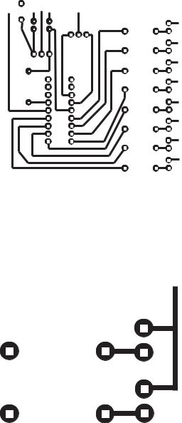
616 |
|
|
|
|
|
|
Appendix B |
|
|
|
|
|
|
|
|
|
|
|
|
|
|
|
|
|
|
|
|
|
|
|
|
|
|
|
|
|
|
|
|
|
|
|
|
|
|
|
|
Figure B-1 PIC Flasher Circuit Board Drawing
Note in the drawing that the circuit locations where the components are to be soldered consist of small circular pads, usually called solder pads. The following illustration zooms into the lower corner of the drawing to show the details of the solder pads.
Figure B-2 Detail of Circuit Board Pads
Quite often it is necessary for a circuit line to cross between two standard pads. In this case the pads can be modified so as to allow it. The modified pads are shown in Figure B-3.

Building Your Own Circuit Boards |
617 |
|||||||||||||
|
|
|
|
|
|
|
|
|
|
|
|
|
|
|
|
|
|
|
|
|
|
|
|
|
|
|
|
|
|
|
|
|
|
|
|
|
|
|
|
|
|
|
|
|
|
|
|
|
|
|
|
|
|
|
|
|
|
|
|
|
|
|
|
|
|
|
|
|
|
|
|
|
|
|
|
|
|
|
|
|
|
|
|
|
|
|
|
|
|
|
|
|
|
|
|
|
|
|
|
|
|
|
|
|
|
|
|
|
|
|
|
|
|
|
|
|
|
|
|
|
|
|
|
|
|
|
|
|
|
|
|
|
|
|
|
|
|
|
|
|
|
|
|
|
|
|
|
|
|
|
|
|
|
|
|
|
|
|
|
|
|
|
|
|
|
|
|
|
|
|
|
|
|
|
|
|
|
|
|
|
|
|
|
|
|
|
|
|
|
|
|
|
|
|
|
|
|
|
|
|
|
|
|
|
|
|
|
|
|
|
|
|
|
|
|
|
|
|
|
|
|
|
|
|
Figure B-3 Modified Circuit Boards Pads
Printing the PCB Diagram
The circuit diagram must be printed using a laser printer. Inkjet toners do not produce an image that resist the action of the etchant. Although in our experiments we used LaserJet printers it is well documented that virtually any laser printer will work. Laser copiers have also been used successfully for creating the PCB circuit image.
With the method we are describing, the width of the traces can become an issue. The traces in the PCB image of Figure B-1 are 2 points, which is 0.027". Traces half that width and less have been used successfully with this method but as the traces become thinner the entire process becomes more critical. For most simple circuits 0.020" traces should be a useful limit. Also be careful not to touch the glossy side of the paper or the printed image with fingers.
Note that the pattern is drawn as if you were looking from the component side of the board.
Transferring the PCB Image
Users of this method state that one of the most critical elements is the paper used in printing the circuit. Pinholes in some papers can degrade the image to the point that the circuit lines (especially if they are very thin) do not etch correctly. Another problem relates to removing the ironed-on paper from the board without damaging the board surface.
Glossy, coated inkjet-printer paper works well. Even better results can be obtained with glossy photo paper. We use a common high-gloss photographic paper available from Staples and sold under the name of "picture paper". The 30 sheets, 8-by-10 size, have the Staples number B031420197 1713. The UPC barcode is: 7 18103 02238 5.
618 |
Appendix B |
Transferring the image onto the board blank is done by applying heat from a common clothes iron, set on the hottest setting, onto the paper/board sandwich. In most irons the hottest setting is labeled “linen.” After going over the back of the paper several times with the hot iron, the paper becomes fused to the copper side of the blank board. The board/paper sandwich is then allowed to soak in water for about
10 minutes, after which the paper can be removed by peeling or light scrubbing with a toothbrush. It has been mentioned that Hewlett-Packard toner cartridges with microfine particles work better than the store-brand toner cartridges.
Etching the Board
Once the paper has been removed and the board washed it is time to prepare the board for etching. The preliminary operations consist of rubbing the copper surface of the board with Scotchbrite plastic abrasive pad and then scrubbing the surface with a paper towel soaked with Acetone solvent.
When the board is rubbed and clean, it is time to etch the circuit. The etching solution contains Ferric Chloride and is available from Radio Shack as a solution and from Jameco Electronics as a powder to be mixed by the user. PCB Ferric Chloride etchant should be handled with rubber gloves and rubber apron since it stains the skin and utensils. Also, concentrated acid fumes from Ferric Chloride solution are toxic and can cause severe burns. These chemicals should be handled according to cautions and warnings posted in the containers.
The Ferric Chloride solution should be stored and used in a plastic or glass container, never metal. Faster etching is accomplished if the etching solution is first warmed by placing the bottle in a tub of hot water. Once the board is in the solution, face up, the container is rocked back and forth. It is also possible to aid in the copper removal by rubbing the surface with a rubber-gloved finger.
Finishing the Board
The etched board should be washed well, first in water and then in Lacquer Thinner or Acetone; either solvent works. It is better to just rub the board surface with a paper towel soaked in the solvent. Keep in mind that most solvents are flammable and explosive, and also toxic.
After the board is clean the mounting holes can be drilled using the solder pads as a guide. A small electric drill at high revolutions, such as a Dremmel tool, works well for this operation. The standard drill size for the mounting holes is 0.035". A #60 drill (0.040") also works well. Once all the holes are drilled, the components can be mounted from the backside and soldered at the pads.
The Backside Image
The component side (backside) of the PCB can be printed with an image of the components to be mounted or with logos or other text. A single-sided blank board has no copper coating on the backside so the image is just ironed on without etching. Probably the best time to print the backside image is after the board has been etched and drilled but before mounting the components.
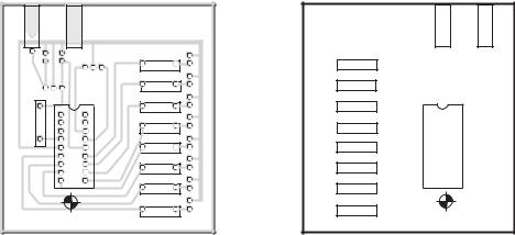

622 |
|
|
|
Appendix C |
|
|
Table C.1 |
|
|
|
Mid-range PIC Instruction Set (continued) |
|
||
|
|
|
|
|
|
|
|
|
BITS |
MNEMONIC |
OPERAND |
DESCRIPTION |
CYCLES |
AFFECTED |
|
|
|
||
|
LITERAL AND CONTROL OPERATIONS |
|
||
ANDLW |
k |
AND literal and w |
1 |
Z |
CALL |
k |
Call procedure |
2 |
- |
CLRWDT |
- |
Clear watchdog timer |
1 |
TO,PD |
GOTO |
k |
Go to address |
2 |
- |
IORLW |
k |
Inclusive OR literal with w |
1 |
Z |
MOVLW |
k |
Move literal to w |
1 |
- |
RETFIE |
- |
Return from interrupt |
2 |
- |
RETLWk |
- |
Return literal in w |
2 |
- |
RETURN |
- |
Return from procedure |
2 |
- |
SLEEP |
- |
Go into SLEEP mode |
1 |
TO,PD |
SUBLW |
k |
Subtract literal and w |
1 |
C,DC,Z |
XORLW |
k |
Exclusive OR literal |
1 |
Z |
|
|
with w |
|
|
Legend: |
|
|
|
|
f = file register |
|
|
|
|
d = destination: |
0 = w register |
|
|
|
b = bit position |
1 = file register |
|
|
|
|
|
|
||
k = 8-bit constant |
|
|
|
|
|
|
|
|
|
Mid-range Instruction Set |
623 |
|
Table C.2 |
|
Conventions used in Instruction Descriptions |
|
|
FIELD |
DESCRIPTION |
|
|
f |
Register file address (0x00 to 0x7F) |
w |
Working register (accumulator) |
b |
Bit address within an 8-bit file register (0 to 7) |
kLiteral field, constant data or label (may be either an 8-bit or an 11-bit value)
x |
Don't care (0 or 1) |
d |
Destination select; |
|
d = 0: store result in W, |
|
d = 1: store result in file register f. |
dest |
Destination either the W register or the specified register file |
|
location |
label |
Label name |
TOS |
Top of Stack |
PC |
Program Counter |
PCLATH |
Program Counter High Latch |
GIE |
Global Interrupt Enable bit |
WDT |
Watchdog Timer |
!TO |
Time-out bit |
!PD |
Power-down bit |
[ ] |
Optional element |
[XXX]Contents of memory location pointed at by XXX register
( ) |
Contents |
-> |
Assigned to |
< > |
Register bit field |
italics User defined term
624 Appendix C
ADDLW |
Add Literal and w |
|
|
Syntax: |
[label] ADDLW |
k |
|
Operands: |
k in range 0 to 255 |
|
|
Operation: |
(w) + k -> w |
|
|
Status Affected: |
C, DC, Z |
|
|
Description: |
The contents of the w register are added to |
||
|
the eight bit literal 'k' and the result is |
||
|
placed in the w register |
||
Words: |
1 |
|
|
Cycles: |
1 |
|
|
Example1: |
|
|
|
|
ADDLW |
0x15 |
|
|
Before Instruction: |
w = 0x10 |
|
|
After Instruction: |
w = 0x25 |
|
Example 2: |
|
|
|
|
ADDLW |
var1 |
|
|
Before Instruction: |
w = 0x10 |
|
|
var1 is data memory variable |
||
|
var1 = 0x37 |
|
|
|
After Instruction |
w = 0x47 |
|
Mid-range Instruction Set |
625 |
ADDWF |
Add w and f |
Syntax: |
[ label ] ADDWF f,d |
Operands: |
f in range 0 to 127 |
|
d = 0 / 1 |
Operation: |
(W) + (f) -> destination |
Status Affected: |
C, DC, Z |
Description: |
Add the contents of the W register with |
|
register 'f'. If 'd' is 0 the result is stored in |
|
the w register. If 'd' is 1 the result is stored |
|
back in register 'f'. |
Words: |
1 |
Cycles: |
1 |
Example 1: |
|
ADDWF FSR,0
Before Instruction:
w = 0x17
FSR = 0xc2
After Instruction
W = 0xd9
FSR = 0xc2
Example 2:
ADDWF INDF, 1 before Instruction:
W = 0x17
FSR = 0xC2
Contents of Address (FSR) = 0x20
After Instruction
W = 0x17
FSR = 0xC2
Contents of Address (FSR) = 0x37
626 Appendix C
BCF |
Bit Clear f |
|
Syntax: |
[ label ] BCF f,b |
|
Operands: |
f in range 0 to 127 |
|
|
b in range 0 to 7 |
|
Operation: |
0 ->f<b> |
|
Status Affected: |
None |
|
Description: |
Bit 'b' in register 'f' is cleared. |
|
Words: |
1 |
|
Cycles: |
1 |
|
Example 1: |
|
|
BCF |
reg1,7 |
|
Before Instruction: reg1 = 0xc7 (1100 0111) |
||
After Instruction: reg1 = 0x47 (0100 0111) |
||
Example 2: |
|
|
BCF |
INDF,3 |
|
Before Instruction: |
w = 0x17 |
|
|
|
FSR = 0xc2 |
|
|
[FSR]= 0x2f |
After Instruction |
|
|
|
|
w = 0x17 |
|
|
FSR = 0xc2 |
|
|
[FSR] = 0x27 |
Mid-range Instruction Set |
627 |
BSF |
Bit Set f |
Syntax: |
[ label ] BSF f,b |
Operands: |
f in range 0 to 127 |
|
b in range 0 to 7 |
Operation: |
1-> f<b> |
Status Affected: |
None |
Description: |
Bit 'b' in register 'f' is set. |
Words: |
1 |
Cycles: |
1 |
Example 1:
BSF |
reg1,6 |
|
|
Before Instruction : |
reg1 = 0011 |
1010 |
|
After Instruction: |
reg1 = 0111 |
1010 |
|
Example 2: |
|
|
|
BSF |
INDF,3 |
|
|
Before Instruction: |
w = 0x17 |
|
|
|
|
FSR = 0xc2 |
|
|
|
[FSR] = 0x20 |
|
After Instruction
w = 0x17 FSR = 0xc2
[FSR] = 0x28
628 |
Appendix C |
BTFSC |
Bit Test f, Skip if Clear |
|
Syntax: |
[ label ] BTFSC |
f,b |
Operands: |
f in range 0 to 127 |
|
|
b in range 0 to 7 |
|
Operation: |
skip next instruction if (f<b>) = 0 |
|
Status Affected: |
None |
|
Description: |
If bit 'b' in register 'f' is '0' then the next |
|
|
instruction is skipped. If bit 'b' is '0' then the |
|
|
next instruction (fetched during the current in- |
|
|
struction execution) is discarded, and a NOP |
|
|
is executed instead, making this a 2 cycle |
|
|
instruction. |
|
Words: |
1 |
|
Example 1: |
|
|
|
repeat: |
|
|
btfsc |
reg1,4 |
|
goto |
repeat |
Case 1: Before Instruction
PC = $
reg1 = xxx0 xxxx After Instruction
Since reg1<4>= 0,
PC = $ + 2 (goto skipped)
Case 2: Before Instruction
PC = $
reg1= xxx1 xxxx After Instruction
Since FLAG<4>=1,
PC = $ + 1 (goto executed)
Mid-range Instruction Set |
629 |
BTFSS |
Bit Test f, Skip if Set |
|
Syntax: |
[ label ] BTFSC |
f,b |
Operands: |
f in range 0 to 127 |
|
|
b in range 0 to 7 |
|
Operation: |
skip next instruction if (f<b>) = 1 |
|
Status Affected: |
None |
|
Description: |
If bit 'b' in register 'f' is '1' then the next |
|
|
instruction is skipped. If bit 'b' is '0' then the |
|
|
next instruction (fetched during the current |
|
|
instruction execution) is discarded, and a NOP |
|
|
is executed instead, making this a 2 cycle |
|
|
instruction. |
|
Words: |
1 |
|
Cycles: |
1(2) |
|
|
repeat: |
|
|
btfss |
reg1,4 |
|
goto |
repeat |
Case 1: Before Instruction
PC = $
Reg1 = xxx1 xxxx
After Instruction
Since Reg1<4>= 1,
PC = $ + 2 (goto skipped)
Case 2: Before Instruction
PC = $
Reg1 = xxx0 xxxx
After Instruction
Since Reg1<4>=0,
PC = $ + 1 (goto executed)
630 |
Appendix C |
CALL |
Call Subroutine |
|
Syntax: |
[ label ] CALL |
k |
Operands: |
k in range 0 to 2047 |
|
Operation: |
(PC) + -> TOS, |
|
|
k-> PC<10:0>, |
|
|
(PCLATH<4:3>)-> PC<12:11> |
|
Status Affected: |
None |
|
Description: |
Call Subroutine. First, the 13-bit return address |
|
|
(PC+1) is pushed onto the stack. The eleven bit |
|
|
immediate address is loaded into PC bits |
|
|
<10:0>. The upper bits of the PC are loaded |
|
|
from PCLATH<4:3>. CALL is a two cycle |
|
|
instruction. |
|
Words: |
1 |
|
Cycles: |
2 |
|
Example 1: |
|
|
Here:
call There
Before Instruction
PC = AddressHere
After Instruction
TOS = Address Here + 1
PC = Address There
Mid-range Instruction Set |
631 |
CLRF |
Clear f |
|
Syntax: |
[ label ] CLRF |
f |
Operands: |
f in range 0 to 127 |
|
Operation: |
00h ->f |
|
|
1-> Z |
|
Status Affected: |
Z |
|
Description: |
The contents of register 'f' are cleared and |
|
|
the Z bit is set. |
|
Words: |
1 |
|
Cycles: |
1 |
|
Example 1: |
|
|
clrf |
reg1 |
|
Before Instruction: |
reg1 = 0x5a |
|
After Instruction: |
reg1 = 0x00 |
|
|
|
Z = 1 |
Example 2: |
|
|
Clrf |
INDF |
|
Before Instruction: |
FSR = 0xc2 |
|
|
|
[FSR]= 0xAA |
After Instruction: |
FSR = 0xc2 |
|
|
|
[FSR] = 0x00 |
|
|
Z = 1 |
632 |
Appendix C |
CLRW |
Clear w |
Syntax: |
[ label ] CLRW |
Operands: |
None |
Operation: |
00h -> w |
|
1-> Z |
Status Affected: |
Z |
Description: |
w register is cleared. Zero bit (Z) is set. |
Words: |
1 |
Cycles: |
1 |
Example 1:
CLRW
Before Instruction: |
w = 0x5A |
||
After Instruction: |
w |
= |
0x00 |
|
Z |
= |
1 |
Mid-range Instruction Set |
633 |
CLRWDT |
Clear Watchdog Timer |
||
Syntax: |
[ label ] CLRWDT |
|
|
Operands: |
None |
|
|
Operation: |
00h -> WDT |
|
|
|
0 |
-> WDT prescaler count, |
|
|
1 |
-> TO |
|
|
1 |
-> PD |
|
Status Affected: |
TO, PD |
|
|
Description: |
CLRWDT instruction clears the Watchdog |
||
|
Timer. It also clears the prescaler |
||
|
count of the WDT. Status bits TO and PD are |
||
|
set. The instruction does not change the |
||
|
assignment of the WDT prescaler. |
||
Words: |
1 |
|
|
Cycles: |
1 |
|
|
Example 1: |
|
|
|
|
CLRWDT |
|
|
|
Before Instruction: |
WDT counter= x |
|
|
|
|
WDT prescaler = 1:128 |
|
After Instruction: |
WDT counter=0x00 |
|
|
|
|
WDT prescaler count=0 |
|
|
|
TO = 1 |
PD = 1
WDT prescaler = 1:128
634 |
Appendix C |
COMF |
Complement f |
|
Syntax: |
[ label ] COMF |
f,d |
Operands: |
f in range 0 to 127 |
|
|
d is 0 or 1 |
|
Operation: |
(f) -> destination |
|
Status Affected: |
Z |
|
Description: |
The contents of register 'f' are 1’s |
|
|
complemented. If 'd' is 0 the result is stored in |
|
|
w. If 'd' is 1 the result is stored back in register |
|
|
'f'. |
|
Words: |
1 |
|
Cycles: |
1 |
|
Example 1:
comf |
reg1,0 |
|
|
|
Before Instruction: |
reg1 |
= |
0x13 |
|
After Instruction: |
reg1 |
= |
0x13 |
|
|
|
|
|
w = 0xEC |
Example 2: |
|
|
|
|
comf |
INDF,1 |
|
Before Instruction: |
FSR = 0xc2 |
|
|
|
[FSR]= 0xAA |
After Instruction: |
FSR = 0xc2 |
|
|
|
[FSR] = 0x55 |
Example 3: |
|
|
comf |
reg1,1 |
|
Before Instruction: |
reg1= 0xff |
|
After Instruction: |
reg1 = 0x00 |
|
Mid-range Instruction Set |
635 |
DECF |
Decrement f |
|
|
Syntax: |
[ label ] DECF f,d |
|
|
Operands: |
f in range 0 to 127 |
|
|
|
d is either 0 or 1 |
|
|
Operation: |
(f) - 1 -> destination |
|
|
Status Affected: |
Z |
|
|
Description: |
Decrement register 'f'. If 'd' is 0 the result is |
||
|
stored in the w register. If 'd' is 1 the |
||
|
result is stored back in register 'f'. |
||
Words: |
1 |
|
|
Cycles: |
1 |
|
|
Example 1: |
|
|
|
|
decf |
count,1 |
|
|
Before Instruction: |
count = 0x01 |
|
|
|
|
Z = 0 |
|
After Instruction: |
count = 0x00 |
|
|
|
|
Z = 1 |
Example 2: |
|
|
|
|
decf |
INDF,1 |
|
|
Before Instruction: |
FSR = 0xc2 |
|
|
|
|
[FSR] = 0x01 |
|
|
|
Z = 0 |
|
After Instruction: |
FSR = 0xc2 |
|
|
|
|
[FSR] = 0x00 |
|
|
|
Z = 1 |
Example 3: |
|
|
|
|
decf |
count,0 |
|
|
Before Instruction: |
count = 0x10 |
|
|
|
|
w = x |
|
|
|
Z = 0 |
|
After Instruction: |
count = 0x10 |
|
|
|
|
w = 0x0f |
636 |
Appendix C |
DECFSZ |
Decrement f, Skip if 0 |
|
Syntax: |
[ label ] DECFSZ f,d |
|
Operands: |
f in the range 0 to 127 |
|
|
d is either 0 or 1 |
|
Operation: |
(f) - 1 -> destination; skip if result = 0 |
|
Status Affected: |
None |
|
Description: |
The contents of register 'f' are |
|
|
decremented. If 'd' is 0 the result is placed |
|
|
in the w register. If 'd' is 1 the result is |
|
|
placed back in register 'f'. |
|
|
If the result is 0, then the next instruction |
|
|
(fetched during the current instruction |
|
|
execution) is discarded and a NOP is |
|
|
executed instead, making this a 2 cycle |
|
|
instruction. |
|
Words: |
1 |
|
Cycles: |
1(2) |
|
Example |
|
|
here: |
|
|
decfsz |
count,1 |
|
goto |
here |
|
Case 1: |
|
|
Before Instruction: |
PC = $ |
|
|
|
count = 0x01 |
After Instruction: |
count = 0x00 |
|
|
|
PC = $ + 2 (goto skipped) |
Case 2: |
|
|
Before Instruction: |
PC = $ |
|
|
|
count = 0x04 |
After Instruction: |
count = 0x03 |
|
|
|
PC = $ + 1 (goto executed) |
Mid-range Instruction Set |
637 |
GOTO |
Unconditional Branch |
||
Syntax: |
[ label ] GOTO k |
|
|
Operands: |
0 £ k £ 2047 |
|
|
Operation: |
k -> PC<10:0> |
|
|
|
PCLATH<4:3> ->PC<12:11> |
||
Status Affected: |
None |
|
|
Description: |
GOTO is an unconditional branch. The eleven |
||
|
bit immediate value is loaded into PC bits |
||
|
<10:0>. The upper bits of PC are loaded from |
||
|
PCLATH<4:3>. |
|
|
|
GOTO is a two cycle instruction. |
||
Words: |
1 |
|
|
Cycles: |
2 |
|
|
Example |
|
|
|
|
goto |
There |
|
|
After Instruction: |
PC = address of There |
|
638 Appendix C
INCF |
|
Increment f |
|
Syntax: |
[ label ] INCF f,d |
|
|
Operands: |
f in range 0 to 127 |
|
|
|
d is either 0 or 1 |
|
|
Operation: |
(f) + 1 -> destination |
|
|
Status Affected: |
Z |
|
|
Description: |
The contents of register 'f' are incremented. If |
||
|
'd' is 0 the result is placed in the w register. If 'd' |
||
|
is 1 the result is placed back in register 'f'. |
||
Words: |
1 |
|
|
Cycles: |
1 |
|
|
Example 1 |
|
|
|
|
incf |
count,1 |
|
|
Before Instruction: |
count = 0xff |
|
|
|
|
Z = 0 |
|
After Instruction: |
count = 0x00 |
|
|
|
|
Z = 1 |
Example 2 |
|
|
|
|
incf |
INDF,1 |
|
|
Before Instruction: |
FSR = 0xC2 |
|
|
|
|
[FSR] = 0xff |
|
|
|
Z = 0 |
|
After Instruction: |
FSR = 0xc2 |
|
|
|
|
[FSR] = 0x00 |
|
|
|
Z = 1 |
Example 3 |
|
|
|
|
incf |
count,0 |
|
|
Before Instruction: |
count = 0x10 |
|
|
|
|
w = x |
|
|
|
Z = 0 |
|
After Instruction: |
count = 0x10 |
|
|
|
|
w = 0x11 |
|
|
|
Z = 0 |
Mid-range Instruction Set |
639 |
INCFSZ |
Increment f, Skip if 0 |
||
Syntax: |
[ label ] INCFSZ f,d |
||
Operands: |
f in range 0 to 127 |
||
|
d is either 0 or 1 |
||
Operation: |
(f) + 1 -> destination, skip if result = 0 |
||
Status Affected: |
None |
|
|
Description: |
The contents of register 'f' are incremented. If |
||
|
'd' is 0 the result is placed in the w register. If 'd' |
||
|
is 1 the result is placed back in register 'f'. |
||
|
If the result is 0, then the next instruction |
||
|
(fetched during the current instruction |
||
|
execution) is discarded and a NOP is executed |
||
|
instead, making this a 2 cycle instruction. |
||
Words: |
1 |
|
|
Cycles: |
1(2) |
|
|
Example |
|
|
|
Here: |
|
|
|
|
incfsz |
count,1 |
|
|
goto |
Here |
|
Case 1: |
|
|
|
Before Instruction: |
PC = $ |
||
|
|
|
count = 0x10 |
After Instruction: |
count = 0x11 |
||
|
|
|
PC = $ + 1 (goto executed) |
Case 2: |
|
|
|
Before Instruction: |
PC = $ |
||
|
|
|
count = 0x00 |
After Instruction: |
count = 0x01 |
||
|
|
|
PC = $ + 2 (goto skipped) |
640 Appendix C
IORLW |
Inclusive OR Literal with w |
Syntax: |
[ label ] IORLW k |
Operands: |
k is in range 0 to 255 |
Operation: |
(w).OR. k -> w |
Status Affected: |
Z |
Description: |
The contents of the w register is OR’ed with |
|
the eight bit literal 'k'. The result is placed in the |
|
w register. |
Words: |
1 |
Cycles: |
1 |
Example 1
iorlw 0x35 |
|
|
|
Before Instruction: |
w = |
0x9a |
|
After Instruction: |
w |
= |
0xbfF |
|
Z |
= |
0 |
Example 2 |
|
|
|
iorlw myreg |
|
Before Instruction: |
w = 0x9a |
Myreg is a variable representing a location |
|
in PIC RAM. |
[Myreg] = 0x37 |
After Instruction: |
w = 0x9F |
|
Z = 0 |
Example 3 |
|
iorlw 0x00
Before Instruction: |
w |
= |
0x00 |
After Instruction: |
w |
= |
0x00 |
Mid-range Instruction Set |
641 |
IORWF |
|
Inclusive OR w with f |
|
Syntax: |
[ label ] IORWF f,d |
|
|
Operands: |
f is in range 0 to 127 |
|
|
|
d is either 0 or 1 |
|
|
Operation: |
(W).OR. (f) -> destination |
||
Status Affected: |
Z |
|
|
Description: |
Inclusive OR the w register with register 'f'. If 'd' |
||
|
is 0 the result is placed in the w register. If 'd' is |
||
|
1 the result is placed back in register 'f'. |
||
Words: |
1 |
|
|
Cycles: |
1 |
|
|
Example 1 |
|
|
|
|
iorwf |
result,0 |
|
|
Before Instruction: |
result = 0x13 |
|
|
|
|
w = 0x91 |
|
After Instruction: |
result = 0x13 |
|
|
|
|
w = 0x93 |
|
|
|
Z = 0 |
Example 2 |
|
|
|
|
iorwf |
INDF,1 |
|
|
Before Instruction: |
w = 0x17 |
|
|
|
|
FSR = 0xc2 |
|
|
|
[FSR] = 0x30 |
|
After Instruction: |
w = 0x17 |
|
|
|
|
FSR = 0xc2 |
|
|
|
[FSR] = 0x37 |
|
|
|
Z = 0 |
Example 3 |
|
|
|
|
iorwf |
result,1 |
|
Case 1: |
Before Instruction: |
result = 0x13 |
|
|
|
|
w = 0x91 |
|
After Instruction: |
result = 0x93 |
|
|
|
|
w = 0x91 |
|
|
|
Z = 0 |
Case 2: |
Before Instruction: |
result = 0x00 |
|
|
|
|
w = 0x00 |
|
After Instruction: |
result = 0x00 |
|
|
|
|
w = 0x00 |
|
|
|
Z = 1 |
642 Appendix C
MOVF |
Move f |
|
|
Syntax: |
[ label ] MOVF |
f,d |
|
Operands: |
f is in range 0 to 127 |
||
|
d is either 0 or 1 |
|
|
Operation: |
(f) -> destination |
|
|
Status Affected: |
Z |
|
|
Description: |
The contents of register ’f’ is moved to a |
||
|
destination dependent upon the status of ’d’. If |
||
|
’d’ = 0, destination is W register. If ’d’ = 1, the |
||
|
destination is file register ’f’ itself. ’d’ = 1 is |
||
|
useful to test a file register since status flag Z |
||
|
is affected. |
|
|
Words: |
1 |
|
|
Cycles: |
1 |
|
|
Example 1 |
|
|
|
|
movf |
FSR,0 |
|
|
Before Instruction: |
w = 0x00 |
|
|
|
|
FSR = 0xc2 |
|
After Instruction: |
w = 0xc2 |
|
|
|
|
Z = 0 |
Example 2 |
|
|
|
|
movf |
INDF,0 |
|
|
Before Instruction: |
w = 0x17 |
|
|
|
|
FSR = 0xc2 |
|
|
|
[FSR] = 0x00 |
|
After Instruction: |
w = 0x17 |
|
|
|
|
FSR = 0xc2 |
|
|
|
[FSR] = 0x00 |
|
|
|
Z = 1 |
Example 3 |
|
|
|
|
movf |
FSR,1 |
|
Case 1: |
Before Instruction: |
FSR = 0x43 |
|
|
After Instruction: |
FSR = 0x43 |
|
|
|
|
Z = 0 |
Case 2: |
Before Instruction: |
FSR = 0x00 |
|
|
After Instruction: |
FSR = 0x00 |
|
|
|
|
Z = 1 |
Mid-range Instruction Set |
643 |
MOVLW |
Move Literal to w |
Syntax: |
[ label ] MOVLW k |
Operands: |
k in range 0 to 255 |
Operation: |
k- > w |
Status Affected: |
None |
Description: |
The eight bit literal 'k' is loaded into W register. |
|
The don’t cares will assemble as 0’s. |
Words: |
1 |
Cycles: |
1 |
Example 1
movlw |
0x5a |
|
After Instruction: |
w = 0x5A |
|
Example 2 |
|
|
movlw |
myreg |
|
Before Instruction: |
w = 0x10 |
|
|
|
[myreg] = 0x37 |
After Instruction: |
w = 0x37 |
|
644 Appendix C
MOVWF |
Move w to f |
Syntax: |
[ label ] MOVWF f |
Operands: |
f in range 0 to 127 |
Operation: |
(w) -> f |
Status Affected: |
None |
Description: |
Move data from W register to register 'f'. |
Words: |
1 |
Cycles: |
1 |
Example 1
movwf OPTION_REG |
|
Before Instruction: |
OPTION_REG = 0xff |
|
w = 0x4f |
After Instruction: |
OPTION_REG = 0x4f |
|
w = 0x4f |
Example 2 |
|
movwf INDF
Before Instruction: |
w = |
0x17 |
|
|
FSR |
= |
0xC2 |
|
[FSR] |
= 0x00 |
|
After Instruction: |
w = |
0x17 |
|
|
FSR |
= |
0xC2 |
|
[FSR] |
= 0x17 |
|
Mid-range Instruction Set |
645 |
NOP |
No Operation |
Syntax: |
[ label ] NOP |
Operands: |
None |
Operation: |
No operation |
Status Affected: |
None |
Description: |
No operation. |
Words: |
1 |
Cycles: |
1 |
Example
nop
Before Instruction: |
PC |
= |
$ |
|
fter Instruction: |
PC |
= |
$ |
+ 1 |
Mid-range Instruction Set |
647 |
RETFIE |
Return from Interrupt |
Syntax: |
[ label ] RETFIE |
Operands: |
None |
Operation: |
TOS -> PC, |
|
1 -> GIE |
Status Affected: |
None |
Description: |
Return from Interrupt. The 13-bit address at the |
|
Top of Stack (TOS) is loaded in the PC. The |
|
Global Interrupt Enable bit, GIE (INTCON<7>), |
|
Is automatically set, enabling Interrupts. This is |
|
a two cycle instruction. |
Words: |
1 |
Cycles: |
2 |
Example
retfie
After Instruction: |
PC = TOS |
|
GIE = 1 |
648 Appendix C
RETLW |
|
Return with Literal in W |
||
Syntax: |
[ label ] RETLW k |
|
||
Operands: |
k in range 0 to 255 |
|
||
Operation: |
k -> w; |
|
|
|
|
TOS -> PC |
|
|
|
Status Affected: |
None |
|
|
|
Description: |
The w register is loaded with the eight bit literal |
|||
|
'k'. The program counter is loaded 13-bit |
|||
|
address at the Top of Stack (the return |
|||
|
address). This is a two cycle instruction. |
|||
Words: |
1 |
|
|
|
Cycles: |
2 |
|
|
|
Example |
|
|
|
|
|
movlw |
2 |
; Load w with desired |
|
|
|
|
; Table offset |
|
|
call |
table |
; When call returns w |
|
|
|
|
; contains value stored |
|
|
|
|
; in table |
|
Table: |
|
|
|
|
|
addwf |
pc |
; w = offset |
|
|
retlw |
.22 |
; First table entry |
|
|
retlw |
.23 |
; Second table entry |
|
|
retlw |
.24 |
|
|
|
. |
|
|
|
|
. |
|
|
|
|
. |
|
|
|
|
retlw |
.29 |
; Last table entry |
|
|
Before Instruction: |
w = 0x02 |
||
|
After Instruction: |
w = .24 |
||
Mid-range Instruction Set |
649 |
RETURN |
Return from Subroutine |
Syntax: |
[ label ] RETURN |
Operands: |
None |
Operation: |
TOS -> PC |
Status Affected: |
None |
Description: |
Return from subroutine. The stack is POPed |
|
and the top of the stack (TOS) is loaded into |
|
the program counter. This is a two cycle |
|
instruction. |
Words: |
1 |
Cycles: |
2 |
Example
return
After Instruction: PC = TOS
650 Appendix C
RLF |
Rotate Left f through Carry |
||
Syntax: |
[ label ] RLF f,d |
|
|
Operands: |
f in range 0 to 127 |
|
|
|
d is either 0 or 1 |
|
|
Operation: |
See description below |
|
|
Status Affected: |
C |
|
|
Description: |
The contents of register 'f' are rotated one bit to |
||
|
the left through the Carry Flag. If 'd' is 0 the |
||
|
result is placed in the W register. If 'd' is 1 the |
||
|
result is stored back in register 'f'. |
||
Words: |
1 |
|
|
Cycles: |
1 |
|
|
Example 1 |
|
|
|
|
rlf |
reg1,0 |
|
|
Before Instruction: |
reg1 = 1110 0110 |
|
|
|
|
C = 0 |
|
After Instruction: |
reg1 = 1110 0110 |
|
|
|
|
w =1100 1100 |
|
|
|
C =1 |
Example 2 |
|
|
|
|
rlf |
INDF,1 |
|
Case 1: |
Before Instruction: |
w = xxxx xxxx |
|
|
|
|
FSR = 0xc2 |
|
|
|
[FSR] = 0011 1010 |
|
|
|
C = 1 |
|
After Instruction: |
w = 0x17 |
|
|
|
|
FSR = 0xc2 |
|
|
|
[FSR] = 0111 0101 |
|
|
|
C = 0 |
Case 2: |
Before Instruction: |
w = xxxx xxxx |
|
|
|
|
FSR = 0xC2 |
|
|
|
[FSR] = 1011 1001 |
|
|
|
C = 0 |
|
After Instruction: |
w = 0x17 |
|
|
|
|
FSR = 0xC2 |
|
|
|
[FSR] = 0111 0010 |
|
|
|
C = 1 |
Mid-range Instruction Set |
651 |
RRF |
Rotate Right f through Carry |
||
Syntax: |
[ label ] RRF f,d |
|
|
Operands: |
f in range 0 to 127 |
|
|
|
d is either 0 or 1 |
|
|
Operation: |
See description below |
|
|
Status Affected: |
C |
|
|
Description: |
The contents of register 'f' are rotated one bit to |
||
|
the right through the Carry Flag. If 'd' is 0 the |
||
|
result is placed in the w register. If 'd' is 1 the |
||
|
result is placed back in register 'f'. |
||
Words: |
1 |
|
|
Cycles: |
1 |
|
|
Example 1 |
|
|
|
|
rrf |
reg1,0 |
|
|
Before Instruction: |
reg1= 1110 0110 |
|
|
|
|
w = xxxx xxxx |
|
|
|
C = 0 |
|
After Instruction: |
reg1= 1110 0110 |
|
|
|
|
w = 0111 0011 |
|
|
|
C = 0 |
Example 2 |
|
|
|
|
rrf |
INDF,1 |
|
Case 1: |
Before Instruction: |
w = xxxx xxxx |
|
|
|
|
FSR = 0xc2 |
|
|
|
[FSR] = 0011 1010 |
|
|
|
C = 1 |
|
After Instruction: |
w = 0x17 |
|
|
|
|
FSR = 0xC2 |
|
|
|
[FSR] = 1001 1101 |
|
|
|
C = 0 |
Case 2: |
Before Instruction: |
w = xxxx xxxx |
|
|
|
|
FSR = 0xC2 |
|
|
|
[FSR] = 0011 1001 |
|
|
|
C = 0 |
|
After Instruction: |
w = 0x17 |
|
|
|
|
FSR = 0xc2 |
|
|
|
[FSR] = 0001 1100 |
|
|
|
C = 1 |

652 Appendix C
SLEEP
Syntax: |
[ label ] SLEEP |
|
Operands: |
None |
|
Operation: |
00h -> WDT, |
|
|
0 |
-> WDT prescaler count, |
|
1 |
-> TO, |
|
0 |
-> PD |
Status Affected: |
TO, PD |
|
Description: |
The power-down status bit, PD is cleared. |
|
|
Time-out status bit, TO is set. Watchdog Timer |
|
|
and its prescaler count are cleared. The |
|
|
processor is put into SLEEP mode with the |
|
|
oscillator stopped. The SLEEP instruction does |
|
|
not affect the assignment of the WDT |
|
|
prescaler. |
|
Words: |
1 |
|
Cycles: |
1 |
|
Example: |
|
|
SLEEP
Mid-range Instruction Set |
653 |
SUBLW |
Subtract w from Literal |
Syntax: |
[ label ] SUBLW k |
Operands: |
k in range 0 to 255 |
Operation: |
k - (W) -> W |
Status Affected: |
C, DC, Z |
Description: |
The w register is subtracted (2’s complement |
|
method) from the eight bit literal 'k'. The result |
|
is placed in the w register. |
Words: |
1 |
Cycles: |
1 |
Example 1
|
sublw 0x02 |
|
Case 1: |
Before Instruction: |
w = 0x01 |
|
|
C = x |
|
|
Z = x |
|
After Instruction: |
w = 0x01 |
|
|
C = 1 if result + |
|
|
Z = 0 |
Case 2: |
Before Instruction: |
w = 0x02 |
|
|
C = x |
|
|
Z = x |
|
After Instruction: |
w = 0x00 |
|
|
C = 1 ; result = 0 |
|
|
Z = 1 |
Case 3: |
Before Instruction: |
w = 0x03 |
|
|
C = x |
|
|
Z = x |
|
After Instruction: |
w = 0xff |
|
|
C = 0 ; result - |
|
|
Z = 0 |
Example 2 |
|
|
sublw myreg
Before Instruction: |
w = 0x10 |
|
|
||
|
[myreg] |
= 0x37 |
|
||
After Instruction |
w |
= |
0x27 |
|
|
|
C |
= |
1 ; |
result |
+ |
654 Appendix C
SUBWF |
Subtract w from f |
Syntax: |
[ label ] SUBWF f,d |
Operands: |
f in range 0 to 127 |
|
d is either 0 or 1 |
Operation: |
(f) - (W) -> destination |
Status Affected: |
C, DC, Z |
Description: |
Subtract (2’s complement method) w register |
|
from register 'f'. If 'd' is 0 the result is stored in |
|
the w register. If 'd' is 1 the result is stored |
|
back in register 'f'. |
Words: |
1 |
Cycles: |
1 |
Example 1
subwf reg1,1
Case 1: |
Before Instruction: |
reg1 = 3 |
|
|
w = 2 |
|
|
C = x |
|
|
Z = x |
|
After Instruction: |
reg1 = 1 |
|
|
w = 2 |
|
|
C = 1 ; result + |
|
|
Z = 0 |
Case 2: |
Before Instruction: |
reg1 = 2 |
|
|
w = 2 |
|
|
C = x |
|
|
Z = x |
|
After Instruction: |
reg1 = 0 |
|
|
w = 2 |
|
|
C = 1 ; result = 0 |
|
|
Z = 1 |
Case 3: |
Before Instruction: |
reg1 = 1 |
|
|
w = 2 |
|
|
C = x |
|
|
Z = x |
|
After Instruction: |
reg1 = 0xff |
|
|
w = 2 |
|
|
C = 0 ; result is - |
|
|
Z = 0 |
Mid-range Instruction Set |
655 |
SWAPF |
Swap Nibbles in f |
Syntax: |
[ label ] SWAPF f,d |
Operands: |
f in range 0 to 127 |
|
d is either 0 or 1 |
Operation: |
(f<3:0>) -> destination<7:4>, |
|
(f<7:4>) -> destination<3:0> |
Status Affected: |
None |
Description: |
The upper and lower nibbles of register 'f' are |
|
exchanged. If 'd' is 0 the result is placed in w |
|
register. If 'd' is 1 the result is placed in register |
|
'f'. |
Words: |
1 |
Cycles: |
1 |
Example 1
swapf reg,0 |
|
|
Before Instruction: |
reg1 = |
0xa5 |
After Instruction: |
reg1 = |
0xa5 |
|
W = 0x5a |
|
Example 2 |
|
|
Swapf INDF,1 |
|
Before Instruction: |
w = 0x17 |
|
FSR = 0xc2 |
|
[FSR] = 0x20 |
After Instruction: |
w = 0x17 |
|
FSR = 0xC2 |
|
[FSR] = 0x02 |
Example 3 |
|
swapf reg,1
Before Instruction: |
reg1 |
= |
0xa5 |
After Instruction: |
reg1 |
= |
0x5a |
656 Appendix C
TRIS |
Load TRIS Register |
|
Syntax: |
[ label ] TRIS f |
|
Operands: |
f in range 5 to 7 |
|
Operation: |
(W) -> TRIS register f; |
|
Status Affected: |
None |
|
Description: |
The instruction is supported for code |
|
|
compatibility with the PIC16C5X products. |
|
|
Since TRIS registers are readable and writable, |
|
|
code can address these registers directly |
|
Words: |
1 |
|
Cycles: |
1 |
|
Example |
|
|
|
movlw |
B'00000000' |
|
tris |
PORTB |
Mid-range Instruction Set |
657 |
XORLW |
Exclusive OR Literal with W |
||
Syntax: |
[ label] XORLW k |
|
|
Operands: |
k in range 0 to 255 |
|
|
Operation: |
(w).XOR. k -> W |
|
|
Status Affected: |
Z |
|
|
Description: |
The contents of the w register are XOR’ed with |
||
|
the eight bit literal 'k'. The result is placed in the |
||
|
w register. |
|
|
Words: |
1 |
|
|
Cycles: |
1 |
|
|
Example 1 |
|
|
|
|
xorlw |
b’10101111’ |
|
|
Before Instruction: |
w = 1011 0101 |
|
|
After Instruction : |
w = 0001 1010 |
|
|
|
|
Z = 0 |
Example 2 |
|
|
|
|
xorlw |
myreg |
|
|
Before Instruction: |
w = 0xaf |
|
|
|
|
[Myreg] = 0x37 |
|
After Instruction: |
w = 0x18 |
|
|
|
|
Z = 0 |
658 Appendix C
XORWF |
Exclusive OR w with f |
||
Syntax: |
[ label ] XORWF f,d |
|
|
Operands: |
f in range 0 to 127 |
|
|
|
d is either 0 or 1 |
|
|
Operation: |
(W).XOR. (f) -> destination |
||
Status Affected: |
Z |
|
|
Description: |
Exclusive OR the contents of the w register |
||
|
with register 'f'. If 'd' is 0 the result is stored in |
||
|
the w register. If 'd' is 1 the result is stored back |
||
|
in register 'f'. |
|
|
Words: |
1 |
|
|
Cycles: |
1 |
|
|
Example 1 |
|
|
|
|
xorwf |
reg,1 |
|
|
Before Instruction: |
w = 1011 0101 |
|
|
|
|
reg = 1010 1111 |
|
After Instruction: |
reg = 0001 1010 |
|
|
|
|
w = 1011 0101 |
Example 2 |
|
|
|
|
xorwf |
reg,0 |
|
|
Before Instruction |
w = 1011 0101 |
|
|
|
|
reg = 1010 1111 |
|
After Instruction: |
reg = 1010 1111 |
|
|
|
|
w = 0001 1010 |
Example 3 |
|
|
|
|
xorwf |
INDF,1 |
|
|
Before Instruction: |
w = 1011 0101 |
|
|
|
|
FSR = 0xc2 |
|
|
|
[FSR] = 1010 1111 |
|
After Instruction: |
w = 1011 0101 |
|
|
|
|
FSR = 0xc2 |
|
|
|
[FSR] = 0001 1010 |

660 |
Appendix D |
|
processor 16f84A |
|
||
|
include |
<p16f84A.inc> |
|
|
|
__config |
_XT_OSC & _WDT_OFF & _PWRTE_ON & _CP_OFF |
||
;===================================================== |
||||
; |
|
|
PIC register equates |
|
;===================================================== |
||||
porta |
equ |
|
0x05 |
|
portb |
equ |
0x06 |
|
|
status |
equ |
|
0x03 |
|
z |
|
|
equ |
0x02 |
c |
|
|
equ |
0x00 |
tmr0 |
equ |
|
0x01 |
|
; countL |
equ |
|
0x01 |
; Alias for tmr0 |
; |
|
|
|
|
;===================================================== |
||||
; |
|
variables in PIC RAM |
||
;===================================================== |
||||
; Local variables |
|
|
||
|
cblock |
|
0x0d |
; Start of block |
|
J |
|
|
; counter J |
|
K |
|
|
; counter K |
;3-byte auxiliary counter. Low order byte is kept
;in the timer0 register
countM |
; Medium byte |
countH |
; High byte |
endc
;========================================================
; m a i n p r o g r a m
;========================================================
|
org |
0 |
; start at address 0 |
|
goto |
main |
|
; |
|
|
|
;============================= |
|||
; |
interrupt handler |
|
|
;============================= |
|||
|
org |
|
0x04 |
;goto IntServ ;=============================
;main program ;============================= main:
;Clear the watchdog timer and reset prescaler clrf tmr0
clrwdt
;Set up the OPTION register bit map
662 |
Appendix D |
;Timer is designed to count from 0 to 1,000,000
;1,000,000 = 0x0f 0x42 0x40
; |
---- ---- ---- |
|
||
; |
| |
| |
|___ |
(see note) |
; |
| |
|________ |
countM |
|
; |
|_____________ |
countH |
||
;Note:
;The initial count of 0x40 (64 decimal) is ensured
;by initializing the tmr0 register to count 32 timer
;beats at the 1:2 prescaler rate. 128 - 32 = 96 = 0x60
;Initialize the counters:
movlw 0x0f
movwf countH
movlw 0x42
movwf countM
movlw 0x60
movwf tmr0
;Routine tests timer overflow by testing bit 7 of
;the tmr0 register.
cycle:
movlw 3
subwf tmr0,w
btfsc status,c
goto cycle
;Subtract 256 from beat counter by decrementing the
;mid-order byte
decfsz countM,f
goto |
cycle |
; Continue if mid-byte not |
zero
;At this point the mid-order byte has overflowed.
;High-order byte must be decremented.
decfsz countH,f
goto cycle
; At this point one second has elapsed
return
end
Supplementary Programs |
663 |
; File name: SevenSeg.asm
;Date: April 19, 2006
;Author: Julio Sanchez
;Reference: SevenSeg Circuit and Board
;Description:
;Test program for reading four toggle switches and
;displaying the represented hex number on seven-segment
;LED. Also contains a pushbutton switch to activate a
;piezo buzzer. Switches are wired active low.
;
; Switches used in __config directive:
; |
|
_CP_ON |
Code protection ON/OFF |
; * |
_CP_OFF |
|
|
; |
* |
_PWRTE_ON |
Power-up timer ON/OFF |
;_PWRTE_OFF
; |
_WDT_ON |
Watchdog timer ON/OFF |
; * _WDT_OFF |
|
|
; |
_LP_OSC |
Low power crystal occilator |
; * _XT_OSC |
External parallel resonator/crystal oscillator |
|
; |
_HS_OSC |
High speed crystal resonator (8 to 10 MHz) |
; |
|
Resonator: Murate Erie CSA8.00MG = 8 MHz |
; |
_RC_OSC |
Resistor/capacitor oscillator (simplest, 20% |
error)
;|
;|_____ * indicates setup values
;=========================
;setup and configuration ;=========================
processor 16f84A include <p16f84A.inc>
__config _XT_OSC & _WDT_OFF & _PWRTE_ON & _CP_OFF
;
;=====================================================
; |
constant definitions |
; |
(per circuit wiring diagram) |
;=====================================================
#define Pb_sw 4 ; Port A line 4 to push button switch
;
;=====================================================
; PIC register equates
;=====================================================
Porta |
equ |
0x05 |
Portb |
equ |
0x06 |
;============================
664 |
|
|
Appendix D |
; |
local variables |
|
|
;============================ |
|||
|
cblock |
0x0c |
; Start of block |
|
J |
|
; counter J |
|
K |
|
; counter K |
|
endc |
|
|
;============================================================ |
|||
; |
|
|
program |
;============================================================ |
|||
|
org |
0 |
; start at address 0 |
|
goto |
main |
|
; |
|
|
|
; Space for interrupt handlers |
|||
|
org |
0x08 |
|
main: |
|
|
|
|
; Port A. Five low-order lines set for input |
|
|||
movlw |
B'00011111' |
; w = 00011111 binary |
||
tris |
porta |
; port |
A (lines |
0 to 4) to |
input |
|
|
|
|
; Port B. All eight lines for output |
|
|
||
movlw |
B'00000000' |
; w := |
00000000 |
binary |
tris |
portb |
; port |
B to output |
|
;===============================
;Pushbutton switch processing ;=============================== pbutton:
;Push button switch on demo board is wired to port A bit 4
;Switch logic is active low
btfss |
porta,Pb_sw |
; Test and skip if switch bit |
|
|
; set |
goto |
buzzit |
; Buzz if switch ON, |
; At this point port A bit 4 is set (switch is off) |
||
call |
buzoff |
; Buzzer off |
goto |
readdip |
; Read DIP switches |
buzzit: |
|
|
call |
buzon |
; Turn on buzzer |
goto |
pbutton |
|
;============================
;dip switch monitoring ;============================ readdip:
;Read port A switches
movf |
porta,w |
; Port A bits to w |
;Since board is wired active low then all switch bits
;must be negated. This is done by XORing with 1-bits
xorlw |
b'11111111' |
; Invert all bits in w |
; Mask off 4 high-order bits
Supplementary Programs |
665 |
|
andlw |
b'00001111' |
; And with mask |
;At this point the w register contains a 4-bit value
;in the range 0 to 0xf. Use this value (in w) to
;obtain seven-segment display code
call |
segment |
|
|
movwf |
portb |
|
; Display switch bits |
goto |
pbutton |
|
|
;================================ |
|
||
; routine to returns 7-segment |
|
||
; |
codes |
|
|
;================================ |
|
||
segment: |
|
|
|
|
addwf |
PCL,f |
; PCL is program counter latch |
|
retlw |
0x3f |
; 0 code |
|
retlw |
0x06 |
; 1 |
|
retlw |
0x5b |
; 2 |
|
retlw |
0x4f |
; 3 |
|
retlw |
0x66 |
; 4 |
|
retlw |
0x6d |
; 5 |
|
retlw |
0x7d |
; 6 |
|
retlw |
0x07 |
; 7 |
|
retlw |
0x7f |
; 8 |
|
retlw |
0x6f |
; 9 |
|
retlw |
0x77 |
; A |
|
retlw |
0x7c |
; B |
|
retlw |
0x39 |
; C |
|
retlw |
0x5b |
; D |
|
retlw |
0x79 |
; E |
|
retlw |
0x71 |
; F |
|
retlw |
0x7f |
; Just in case all on |
;============================
;piezo buzzer ON ;============================
;Routine to turn on piezo buzzer on port B bit 7 buzon:
bsf |
portb,7 |
; Tune on bit 7, port B |
return
;
;============================
;piezo buzzer OFF ;============================
;Routine to turn off piezo buzzer on port B bit 7 buzoff:
bcf |
portb,7 |
; Bit 7 port b clear |
return
;=============================
; long delay sub-routine
666 |
|
|
|
|
Appendix D |
; |
(for code testing) |
|
|
||
;============================= |
|
||||
long_delay |
|
|
|
||
|
|
|
movlw |
D'200' ; w = 200 decimal |
|
|
|
|
movwf |
J |
; J = w |
jloop: |
movwf |
K |
|
; K = w |
|
kloop: |
decfsz |
K,f |
|
; K = K-1, skip next if zero |
|
|
|
|
goto |
kloop |
|
|
|
|
decfsz |
J,f |
; J = J-1, skip next |
if zero |
|
|
|
|
|
|
|
|
goto |
jloop |
|
|
|
|
return |
|
|
|
|
|
end |
|
|
Supplementary Programs |
667 |
;File name: TestStr.asm
;Date: April 19, 2006
;Author: Julio Sanchez
;Description:
;Program to test sending strings to LCD memory directly
;Program uses delay loops for interface timing.
;WARNING:
;Code assumes 4Mhz clock. Delay routines must be
;edited for faster clock
;Displays: Minnesota State, Mankato
;
;===========================
;switches ;===========================
;Switches used in __config directive:
; |
|
_CP_ON |
Code protection ON/OFF |
; * |
_CP_OFF |
|
|
; |
* |
_PWRTE_ON |
Power-up timer ON/OFF |
;_PWRTE_OFF
; |
_WDT_ON |
Watchdog timer ON/OFF |
|
|
; * _WDT_OFF |
|
|
|
|
; |
_LP_OSC |
Low power crystal |
occilator |
|
; * _XT_OSC |
External parallel |
resonator/crystal oscillator |
||
; |
_HS_OSC |
High speed crystal resonator (8 to |
10 MHz) |
|
; |
|
Resonator: Murate |
Erie CSA8.00MG = |
8 MHz |
; |
_RC_OSC |
Resistor/capacitor oscillator (simplest, 20% |
||
error)
;|
;|_____ * indicates setup values
;========================= ; setup and configuration ;=========================
processor 16f84A
include |
<p16f84A.inc> |
__config |
_XT_OSC & _WDT_OFF & _PWRTE_ON & _CP_OFF |
;===================================================== |
|
; |
constant definitions |
; for PIC-to-LCD pin wiring and LCD line addresses |
|
;===================================================== |
|
#define E_line 1 |
;| |
#define RS_line 2 |
;| -- from wiring diagram |
#define RW_line 3 |
;| |
; LCD line addresses (from LCD data sheet)
668 |
|
|
Appendix D |
#define LCD_1 |
0x80 |
; |
First LCD line constant |
#define LCD_2 |
0xc0 |
; |
Second LCD line constant |
;Note: The constants that define the LCD display line
;addresses have the high-order bit set in
;order to facilitate the controller command
;
;=====================================================
; PIC register equates
;=====================================================
porta |
equ |
0x05 |
Portb |
equ |
0x06 |
fsr |
equ |
0x04 |
Status |
equ |
0x03 |
indf |
equ |
0x00 |
z |
equ |
2 |
;=====================================================
; variables in PIC RAM
;=====================================================
;Reserve 16 bytes for string buffer cblock 0x0c
strData endc
;Leave 16 bytes and Continue with local variables
cblock |
0x1d |
; Start of block |
count1 |
; Counter # 1 |
|
count2 |
; Counter # 2 |
|
count3 |
; Counter # 3 |
|
pic_ad |
; Storage for start of text area |
|
|
; (labeled strData) in PIC RAM |
|
J; counter J
K; counter K
index |
; |
Index into text table (also used |
|
; |
for auxiliary storage) |
endc |
|
|
;============================================================
; program
;============================================================
|
org |
0 |
; start at address |
|
goto |
main |
|
; Space for interrupt handlers |
|
||
org |
|
0x08 |
|
main: |
|
|
|
movlw |
b'00000000' ; All lines to output |
||
tris |
porta |
; in port A |
|
tris |
portb |
; and port B |
|
movlw |
b'00000000' ; All outputs ports low |
||
movwf |
porta |
|
|
Supplementary Programs |
669 |
|
movwf |
portb |
|
; Wait and initialize HD44780 |
|
|
call |
delay_5 |
; Allow LCD time to initialize |
itself |
|
|
call |
initLCD |
; Then do forced |
initialization |
|
|
call |
delay_5 |
; (Wait probably not |
necessary) |
|
|
; Store base address of text buffer in PIC RAM |
||
movlw |
0x0c |
; Start address of text buffer |
movwf |
pic_ad |
; to local variable |
;=========================
;test routine ;=========================
;Set DDRAM address to start of first line
call line1
; Store characters and send directly
|
movlw |
'H' |
|
movwf |
portb |
|
call |
pulseE |
|
movlw |
'e' |
|
movwf |
portb |
|
call |
pulseE |
|
movlw |
'l' |
|
movwf |
portb |
|
call |
pulseE |
|
movlw |
'l' |
|
movwf |
portb |
|
call |
pulseE |
|
movlw |
'o' |
|
movwf |
portb |
|
call |
pulseE |
|
call |
delay_5 |
;======================= |
||
; |
done! |
|
;======================= |
||
loopHere: |
|
|
|
goto |
loopHere ;done |
;************************************************************ ; INITIALIZE LCD PROCEDURE ;************************************************************ initLCD
;Initialization for Densitron LCD module as follows:
;8-bit interface
;2 display lines of 16 characters each
;cursor on
;left-to-right increment
670 |
Appendix D |
;cursor shift right
;no display shift ;***********************|
; |
COMMAND MODE |
| |
|
|
|
|
|
;***********************| |
|
|
|
|
|||
|
bcf |
porta,E_line |
; E line low |
||||
|
bcf |
porta,RS_line |
; RS line low for command |
||||
|
bcf |
porta,RW_line |
; Write mode |
||||
|
call |
delay_125 |
|
|
|
;delay 125 |
|
microseconds |
|
|
|
|
|
|
|
;***********************| |
|
|
|
|
|||
; |
FUNCTION SET |
| |
|
|
|
|
|
;***********************| |
|
|
|
|
|||
|
movlw |
0x38 |
; 0 0 |
1 1 |
1 |
0 0 0 (FUNCTION SET) |
|
|
|
|
; |
| | | |
|__ font select: |
||
|
|
|
; |
| | | |
|
1 = 5x10 in 1/8 or 1/11 |
|
|
|
|
; |
| | | |
|
0 = 1/16 dc |
|
|
|
|
; |
| | |___ Duty cycle select |
|||
|
|
|
; |
| | |
|
|
0 = 1/8 or 1/11 |
|
|
|
; |
| | |
|
|
1 = 1/16 |
|
|
|
; |
| |___ Interface width |
|||
|
|
|
; |
| |
|
0 = 4 bits |
|
|
|
|
; |
| |
|
1 = 8 bits |
|
|
|
|
; |
|___ FUNCTION SET COMMAND |
|||
|
movwf |
portb |
;0011 |
1000 |
|
|
|
|
call |
pulseE |
;pulseE and |
delay |
|||
;***********************| |
|
|
|
|
|||
; |
DISPLAY OFF |
|
| |
|
|
|
|
;***********************| |
|
|
|
|
|||
|
movlw |
0x08 |
; 0 0 |
0 0 1 |
0 0 0 (DISPLAY ON/OFF) |
||
|
|
|
; |
|
| |
| | |___ Blink character |
|
|
|
|
; |
|
| |
| | |
1 = on, 0 = off |
|
|
|
; |
|
| |
| |___ Cursor on/off |
|
|
|
|
; |
|
| |
| |
1 = on, 0 = off |
|
|
|
; |
|
| |
|____ Display on/off |
|
|
|
|
; |
|
| |
|
1 = on, 0 = off |
|
|
|
; |
|
|____ COMMAND BIT |
||
|
movwf |
portb |
|
|
|
|
|
|
call |
pulseE |
;pulseE and |
delay |
|||
;***********************| |
|
|
|
|
|||
; DISPLAY AND CURSOR ON | |
|
|
|
|
|||
;***********************| |
|
|
|
|
|||
|
movlw |
0x0e |
; 0 0 |
0 0 1 |
1 1 0 (DISPLAY ON/OFF) |
||
|
|
|
; |
|
| |
| | |___ Blink character |
|
|
|
|
; |
|
| |
| | |
1 = on, 0 = off |
Supplementary Programs |
|
|
|
|
671 |
||
|
|
|
; |
|
| | |___ Cursor on/off |
|
|
|
|
|
; |
|
| | |
1 = on, 0 = off |
|
|
|
|
; |
|
| |____ Display on/off |
|
|
|
|
|
; |
|
| |
1 = on, 0 = off |
|
|
|
|
; |
|
|____ COMMAND BIT |
|
|
|
movwf |
portb |
|
|
|
|
|
|
call |
pulseE |
;pulseE and delay |
|
|||
;***********************| |
|
|
|
|
|||
; |
ENTRY MODE SET |
| |
|
|
|
|
|
;***********************| |
|
|
|
|
|||
|
movlw |
0x06 |
; 0 0 0 0 |
0 1 1 0 (ENTRY MODE SET) |
|||
|
|
|
; |
|
| | |___ display shift |
||
|
|
|
; |
|
| | |
1 = shift |
|
|
|
|
; |
|
| | |
0 = no shift |
|
|
|
|
; |
|
| |____ cursor increment |
||
|
|
|
; |
|
| |
1 = left-to-right |
|
|
|
|
; |
|
| |
0 = right-to-left |
|
|
|
|
; |
|
|___ COMMAND BIT |
|
|
|
movwf |
portb |
;00000110 |
|
|
|
|
|
call |
pulseE |
|
|
|
|
|
;***********************| |
|
|
|
|
|||
; CURSOR/DISPLAY SHIFT |
| |
|
|
|
|
||
;***********************| |
|
|
|
|
|||
|
movlw |
0x14 |
; 0 0 0 1 |
0 1 0 0 (CURSOR/DISPLAY |
|
||
|
|
|
; |
|
|
SHIFT) |
|
|
|
|
; |
| | | |_|___ don't care |
|
||
|
|
|
; |
| |_|__ cursor/display shift |
|||
|
|
|
; |
| |
|
00 = cursor shift left |
|
|
|
|
; |
| |
|
01 = cursor shift right |
|
|
|
|
; |
| |
|
10 = cursor and display |
|
|
|
|
; |
| |
|
shifted left |
|
|
|
|
; |
| |
|
11 = cursor and display |
|
|
|
|
; |
| |
|
shifted right |
|
|
|
|
; |
|___ COMMAND BIT |
|
||
|
movwf |
portb |
;0001 1111 |
|
|
|
|
|
call |
pulseE |
|
|
|
|
|
;***********************| |
|
|
|
|
|||
; |
CLEAR DISPLAY |
|
| |
|
|
|
|
;***********************| |
|
|
|
|
|||
|
movlw |
0x01 |
; 0 0 0 0 |
0 0 0 1 (CLEAR DISPLAY) |
|
||
|
|
|
|
|
|
; |
|___ |
COMMAND BIT |
|
|
|
|
|
|
|
|
movwf |
portb |
;0000 0001 |
|
|
|
|
; |
|
|
|
|
|
|
|
|
call |
pulseE |
|
|
|
|
|
672 |
Appendix D |
call |
delay_5 ;delay 5 milliseconds after init |
return |
|
;************************************************************
; DELAY AND PULSE PROCEDURES
;************************************************************
;=======================
;Procedure to delay
;42 microseconds ;======================= delay_125
movlw |
D'42' |
; Repeat 42 machine cycles |
movwf |
count1 |
; Store value in counter |
repeat |
|
|
decfsz |
count1,f |
; Decrement counter |
goto |
repeat |
; Continue if not 0 |
return |
|
; End of delay |
;------------------------------------------------------------ |
|
|
;=======================
;Procedure to delay
;5 milliseconds ;======================= delay_5
|
movlw |
D'41' |
; Counter = 41 |
|
|
movwf |
count2 |
; Store in variable |
|
delay |
|
|
|
|
|
call |
delay_125 |
; Delay |
|
|
decfsz |
count2,f |
|
; 40 times = 5 milliseconds |
|
goto |
delay |
|
|
|
return |
|
|
; End of delay |
;======================== |
|
|
||
; |
pulseE E line |
|
|
|
;======================== |
|
|
||
pulseE |
|
|
|
|
|
bsf |
porta,E_line |
;pulse E line |
|
|
bcf |
porta,E_line |
|
|
|
call |
delay_125 |
;delay 125 microseconds |
|
|
return |
|
|
|
;=============================
;long delay sub-routine
;(for debugging) ;============================= long_delay
|
movlw |
D'200' |
; w = 200 decimal |
|
movwf |
J |
; J = w |
jloop: |
movwf |
K |
; K = w |
kloop: |
decfsz |
K,f |
; K = K-1, skip next if zero |
|
|
goto |
kloop |
|
decfsz |
J,f |
; J = J-1, skip next if zero |
Supplementary Programs |
673 |
goto jloop
return
;=============================
;LCD display procedure ;=============================
;Sends 16 characters from PIC buffer with address stored
;in variable pic_ad to LCD line previously selected display16:
;Set up for data
bcf |
porta,E_line |
; E line low |
|
bsf |
porta,RS_line |
; RS line low for control |
|
call |
delay_125 |
; Delay |
|
; Set up counter for 16 characters |
|||
movlw |
D'16' |
|
; Counter = 16 |
movwf |
count3 |
|
|
; Get display address from local variable pic_ad |
|||
movf |
pic_ad,w ; First display RAM address to W |
||
movwf |
fsr |
; W to FSR |
|
getchar: |
|
|
|
movf |
indf,w |
; get character from display RAM |
|
|
|
; location pointed to by file select |
|
|
|
; register |
|
movwf |
portb |
|
|
call |
pulseE |
;send data to display |
|
; Test for 16 characters displayed |
|||
decfsz |
count3,f |
|
; Decrement counter |
goto |
nextchar |
|
; Skipped if done |
return |
|
|
|
nextchar: |
|
|
|
incf |
fsr,f |
|
; Bump pointer |
goto |
getchar |
|
|
;========================
;blank buffer ;========================
;Procedure to store 16 blank characters in PIC RAM
;buffer starting at address stored in the variable
;pic_ad
blank16: |
|
|
|
movlw |
D'16' |
; |
Setup counter |
movwf |
count1 |
|
|
movf |
pic_ad,w ; |
First PIC RAM address |
|
movwf |
fsr |
; |
Indexed addressing |
movlw |
0x20 |
; |
ASCII space character |
storeit: |
|
|
|
movwf |
indf |
; |
Store blank character in PIC RAM |
|
|
; |
buffer using fsr register |
decfsz |
count1,f ; |
Done? |
|
goto |
incfsr |
|
; no |
674 |
|
|
Appendix D |
return |
|
; |
yes |
incfsr: |
|
|
|
incf |
fsr,f |
; |
Bump fsr to next buffer |
space |
|
|
|
goto storeit ;========================
;Set address register
;to LCD line 1 ;========================
;ON ENTRY:
;Address of LCD line 1 in constant LCD_1
line1:
bcf |
porta,E_line |
; E line low |
bcf |
porta,RS_line |
; RS line low, set up for |
|
|
; control |
call |
delay_125 |
; delay 125 microseconds |
; Set to second display line |
|
|
movlw |
LCD_1 |
; Address and command bit |
movwf |
portb |
|
call |
pulseE |
; Pulse and delay |
; Set RS line for data |
|
|
bsf |
porta,RS_line |
; Setup for data |
call |
delay_125 |
; Delay |
return |
|
|
;========================
;Set address register
;to LCD line 2 ;========================
;ON ENTRY:
;Address of LCD line 2 in constant LCD_2
line2:
bcf |
porta,E_line |
; E line low |
bcf |
porta,RS_line |
; RS line low, setup for |
|
|
; control |
call |
delay_125 |
; delay |
; Set to second display line |
|
|
movlw |
LCD_2 |
; Address with high-bit set |
movwf |
portb |
|
call |
pulseE |
; Pulse and delay |
; Set RS line for data |
|
|
bsf |
porta,RS_line |
; RS = 1 for data |
call |
delay_125 |
; delay |
return |
|
|
;=============================== ; first text string procedure ;=============================== storeMSU:
Supplementary Programs |
675 |
;Procedure to store in PIC RAM buffer the message
;contained in the code area labeled msg1
;ON ENTRY:
;variable pic_ad holds address of text buffer
;in PIC RAM
;w register hold offset into storage area
;msg1 is routine that returns the string characters
;and a zero terminator
;index is local variable that hold offset into
;text table. This variable is also used for
;temporary storage of offset into buffer
;ON EXIT:
;Text message stored in buffer
;
;Store offset into text buffer (passed in the w register)
;in temporary variable
movwf |
index |
|
; Store w in index |
; Store base address of text buffer in fsr |
|||
movf |
pic_ad,w ; |
first display RAM address to W |
|
addwf |
index,w |
|
; Add offset to address |
movwf |
fsr |
|
; W to FSR |
; Initialize index for text string access |
|||
movlw |
0 |
; |
Start at 0 |
movwf |
index |
; |
Store index in variable |
; w still = 0 |
|
|
|
get_msg_char: |
|
|
|
call |
msg1 |
; |
Get character from table |
; Test for zero terminator |
|
||
andlw |
0x0ff |
|
|
btfsc |
status,z ; |
Test zero flag |
|
goto |
endstr1 |
; |
End of string |
;ASSERT: valid string character in w
;store character in text buffer (by fsr)
movwf |
indf |
; store in buffer by fsr |
|
incf |
fsr,f |
; increment buffer pointer |
|
; Restore table character counter from variable |
|||
movf |
index,w |
; Get value into w |
|
addlw |
1 |
; Bump to next character |
|
movwf |
index |
; Store table index in variable |
|
goto |
get_msg_char |
; Continue |
|
endstr1: |
|
|
|
return |
|
|
|
; Routine for returning message stored in program area msg1:
addwf |
PCL,f |
; Access table |
retlw |
'M' |
|
retlw |
'i' |
|
676 |
Appendix D |
retlw 'n' retlw 'n' retlw 'e' retlw 's' retlw 'o' retlw 't' retlw 'a' retlw 0
;=================================
;second text string procedure ;================================= storeUniv:
;Processing identical to procedure StoreMSU
movwf |
index |
; |
Store w in index |
; Store base address of text buffer in fsr |
|||
movf |
pic_ad,0 ; |
first display RAM address to W |
|
addwf |
index,0 |
; |
Add offset to address |
movwf |
fsr |
; |
W to FSR |
; Initialize index for text string access |
|||
movlw |
0 |
; |
Start at 0 |
movwf |
index |
; |
Store index in variable |
; w still = 0 |
|
|
|
get_msg_char2: |
|
|
|
call |
msg2 |
; |
Get character from table |
; Test for zero terminator |
|
||
andlw |
0x0ff |
|
|
btfsc |
status,z ; |
Test zero flag |
|
goto |
endstr2 |
; |
End of string |
;ASSERT: valid string character in w
;store character in text buffer (by fsr)
movwf |
indf |
; Store in buffer by fsr |
|
incf |
fsr,f |
; Increment buffer pointer |
|
; Restore table character counter from variable |
|||
movf |
index,w |
; Get value into w |
|
addlw |
1 |
; Bump to next character |
|
movwf |
index |
; Store table index in variable |
|
goto |
get_msg_char2 |
; Continue |
|
endstr2: |
|
|
|
return |
|
|
|
; Routine for returning message stored in program area msg2:
addwf |
PCL,f |
; Access table |
retlw |
'S' |
|
retlw |
't' |
|
retlw |
'a' |
|
retlw |
't' |
|
678 |
Appendix D |
;File: TestDemo1.asm
;Date: June 2, 2006
;Author: Julio Sanchez
;Processor: 16F84A
;Description:
;Program to exercise the demonstration circuit and board
;number 1
;===========================
;switches ;===========================
;Switches used in __config directive:
; |
|
_CP_ON |
Code protection ON/OFF |
; * |
_CP_OFF |
|
|
; |
* |
_PWRTE_ON |
Power-up timer ON/OFF |
;_PWRTE_OFF
; |
_WDT_ON |
Watchdog timer ON/OFF |
|
|
; * _WDT_OFF |
|
|
|
|
; |
_LP_OSC |
Low power crystal |
occilator |
|
; * _XT_OSC |
External parallel |
resonator/crystal |
|
|
; |
|
oscillator |
|
|
; |
_HS_OSC |
High speed crystal resonator (8 to |
10 MHz) |
|
; |
|
Resonator: Murate |
Erie CSA8.00MG = |
8 MHz |
; |
_RC_OSC |
Resistor/capacitor oscillator |
|
|
;|
;|_____ * indicates setup values
processor |
16f84A |
include |
<p16f84A.inc> |
__config |
_XT_OSC & _WDT_OFF & _PWRTE_ON & _CP_OFF |
;=====================================================
; constants
;====================================================
;#define dummy |
100 |
;=====================================================
; variables in PIC RAM
;=====================================================
; with local variables |
|
|
|
|
cblock 0x0c |
; Start of block |
|
; |
hexDig |
; Hex digit |
counter |
|
count1 |
; Counter # |
1 |
|
j |
; counter J |
|
|
k |
; counter K |
|
|
endc |
|
|
;=======================================================
; P R O G R A M
Supplementary Programs |
|
679 |
|
;======================================================= |
|||
org |
0 |
; start at address 0 |
|
goto |
main |
|
|
; |
|
|
|
; Space for interrupt handlers |
|
||
org |
0x08 |
|
|
main: |
|
|
|
; Port A (5 lob) for input |
|
|
|
movlw |
B'00011111' |
; w := 00001111 binary |
|
tris |
PORTA |
|
; port A (lines 0 to 4) to |
input |
|
|
|
; Port bit (8 lines) for output |
|
||
movlw |
B'00000000' |
; w := 00000000 binary |
|
tris |
PORTB |
|
; port B to output |
;==============================
;Pushbutton switch processing ;============================== pbutton:
;Push button switch on demo board is wired to RA4
;Switch logic is active low
btfss |
PORTA,4 |
; Test and skip if bit is set |
goto |
buzzit |
; Buzz if switch ON |
; At this point port A bit 4 is set (switch is off) |
||
call |
buzoff |
; Buzzer off |
goto |
readdip |
; Read DIP switches |
buzzit: |
|
|
call |
buzon |
; Turn on buzzer |
goto |
pbutton |
|
;==============================
;DIP switch processing ;==============================
;Read all bits of port A readdip:
movf |
PORTA,w |
; Port A bits to w |
;If board uses active low then all switch bits must be negated
;This is done by XORing with 1-bits
xorlw |
b'11111111' |
; Invert all bits in w |
; Eliminate all 4 high order bits (just in case) |
||
andlw |
b'00001111' |
; And with mask |
; Get digit into w |
|
|
call |
segment |
; get digit code |
movwf |
PORTB |
; Display digit |
call |
delay |
; Give time |
; Update digit and loop counter |
|
|
goto |
pbutton |
|
;******************************* ; 7-segment table of hex codes
680 |
|
Appendix D |
;******************************* |
||
segment: |
|
|
addwf |
PCL,f |
; PCL is program counter latch |
retlw |
0x3f |
; 0 code |
retlw |
0x06 |
; 1 |
retlw |
0x5b |
; 2 |
retlw |
0x4f |
; 3 |
retlw |
0x66 |
; 4 |
retlw |
0x6d |
; 5 |
retlw |
0x7d |
; 6 |
retlw |
0x07 |
; 7 |
retlw |
0x7f |
; 8 |
retlw |
0x6f |
; 9 |
retlw |
0x77 |
; A |
retlw |
0x7c |
; B |
retlw |
0x39 |
; C |
retlw |
0x5b |
; D |
retlw |
0x79 |
; E |
retlw |
0x71 |
; F |
retlw |
0x7f |
; Just in case all on |
;****************************
;piezo buzzer ON ;****************************
;Routine to turn on piezo buzzer on port B bit 7 buzon:
bsf |
PORTB,7 |
; Tune on bit 7, port B |
|
return |
|
;****************************
;piezo buzzer OFF ;****************************
;Routine to turn off piezo buzzer on port B bit 7 buzoff:
|
bcf |
PORTB,7 |
; Bit |
7 port b clear |
|
return |
|
|
|
;================================ |
|
|||
; |
delay sub-routine |
|
||
;================================ |
|
|||
delay: |
|
|
|
|
|
movlw |
.200 |
; w = 200 decimal |
|
|
movwf |
j |
; j = |
w |
jloop: |
|
|
|
|
|
movwf |
k |
; k = |
w |
kloop: |
|
|
|
|
|
decfsz |
k,f |
; k = |
k-1, skip next if zero |
|
goto |
kloop |
|
|
|
decfsz |
j,f |
; j = |
j-1, skip next if zero |
682 |
Appendix D |
;File: Timer0.ASM
;Date: April 27, 2006
;Author: Julio Sanchez
;Processor: a6F84A
;Description:
;Program to demonstrate programming of the 16F84A
;TIMER0 module. Program flashes eight LEDs in sequence
;counting from 0 to 0xff. Timer0 is used to delay
;the count.
;===========================
;switches ;===========================
;Switches used in __config directive:
; |
|
_CP_ON |
Code protection ON/OFF |
; * |
_CP_OFF |
|
|
; |
* |
_PWRTE_ON |
Power-up timer ON/OFF |
;_PWRTE_OFF
; |
_WDT_ON |
Watchdog timer ON/OFF |
|
|
; * _WDT_OFF |
|
|
|
|
; |
_LP_OSC |
Low power crystal |
occilator |
|
; * _XT_OSC |
External parallel |
resonator/crystal oscillator |
||
; |
_HS_OSC |
High speed crystal resonator (8 to |
10 MHz) |
|
; |
|
Resonator: Murate |
Erie CSA8.00MG = |
8 MHz |
; |
_RC_OSC |
Resistor/capacitor oscillator (simplest, 20% |
||
error)
;|
;|_____ * indicates setup values
|
processor |
16f84A |
|
include |
<p16f84A.inc> |
|
__config |
_XT_OSC & _WDT_OFF & _PWRTE_ON & _CP_OFF |
;===================================================== |
||
; |
variables in PIC RAM |
|
;===================================================== ; None in this application
;
;========================================================
; m a i n p r o g r a m
;========================================================
org |
0 |
; start at address 0 |
goto |
main |
|
;
;=============================
; interrupt handler
;=============================
org |
0x08 |
Supplementary Programs |
683 |
;=============================
;main program ;============================= main:
;Clear the watchdog timer and reset prescaler clrwdt
;Set up the OPTION register bit map
|
|
|
movlw |
|
b'11010111' |
|
|
|
|
|
|
; |
7 |
6 |
5 |
4 |
3 |
2 1 0 <= OPTION bits |
|
|
|||
; |
| |
| |
| |
| |
| |
|__|__|_____ |
PS2-PS0 (prescaler bits) |
||||
; |
| |
| |
| |
| |
| |
|
Values for Timer0 |
|
|||
; |
| |
| |
| |
| |
| |
|
000 |
= 1:2 |
001 |
= 1:4 |
|
; |
| |
| |
| |
| |
| |
|
010 |
= 1:8 |
011 |
= 1:16 |
|
; |
| |
| |
| |
| |
| |
|
100 |
= 1:32 |
101 |
= 1:64 |
|
; |
| |
| |
| |
| |
| |
|
110 |
= 1:128 *111 |
= 1:256 |
||
; |
| |
| |
| |
| |
|______________ |
PSA |
(prescaler assign) |
||||
; |
| |
| |
| |
| |
|
|
1 |
= |
to WDT |
|
|
; |
| |
| |
| |
| |
|
|
*0 |
= |
to Timer0 |
|
|
; |
| |
| |
| |
|_________________ |
TOSE (Timer0 edge select) |
||||||
; |
| |
| |
| |
|
|
|
0 |
= |
increment on |
low-to-high |
|
; |
| |
| |
| |
|
|
|
*1 |
= |
increment in |
high-to-low |
|
; |
| |
| |
|____________________ |
TOCS (TMR0 clock |
source) |
||||||
; |
| |
| |
|
|
|
|
*0 |
= |
internal clock |
||
; |
| |
| |
|
|
|
|
1 |
= |
RA4/TOCKI bit source |
||
; |
| |
|_______________________ |
INTEDG (Edge select) |
||||||||
; |
| |
|
|
|
|
|
*0 |
= |
falling edge |
|
|
;|__________________________ RBPU (Pullup enable)
; |
|
0 = enabled |
; |
|
*1 = disabled |
option |
|
|
; Setup ports |
|
|
movlw |
0x00 |
; Set port B to output |
tris |
PORTB |
|
clrf |
PORTB |
; All port B to 0 |
; Port A is not used in this program |
||
mloop: |
|
|
incf |
PORTB,f |
; Add 1 to register value |
call |
TM0delay |
|
goto |
mloop |
|
;******************************
;delay sub-routine
;uses Timer0 ;****************************** TM0delay:
;Initialize the timer register
clrf |
TMR0 |
; Clear SFR for Timer0 |
;Routine tests the value in the TMR0 register by
;subtracting 0xff from the value in TMR0. The zero flag
684 |
|
Appendix D |
; is set if TMR0 = 0xff |
|
|
cycle: |
|
|
movf |
TMR0,w |
; Timer to w |
; w has TMR0 register value |
|
|
sublw |
0xff |
; Subtract max value |
; Zero flag is set if value in TMR0 = 0xff |
||
btfss |
STATUS,Z ; Test for zero |
|
goto |
cycle |
; Repeat |
return |
|
|
End
Supplementary Programs |
685 |
;File: TimerTst.ASM
;Date: April 27, 2006
;Author: Julio Sanchez
;Description:
;Using the timer to generate a signal at 1 Mhz ;===========================
;switches
;===========================
; Switches used in __config directive:
; |
|
_CP_ON |
Code protection ON/OFF |
; * |
_CP_OFF |
|
|
; |
* |
_PWRTE_ON |
Power-up timer ON/OFF |
;_PWRTE_OFF
; |
_WDT_ON |
Watchdog timer ON/OFF |
|
|
; * _WDT_OFF |
|
|
|
|
; |
_LP_OSC |
Low power crystal |
occilator |
|
; * _XT_OSC |
External parallel |
resonator/crystal oscillator |
||
; |
_HS_OSC |
High speed crystal resonator (8 to |
10 MHz) |
|
; |
|
Resonator: Murate |
Erie CSA8.00MG = |
8 MHz |
; |
_RC_OSC |
Resistor/capacitor oscillator (simplest, 20% |
||
; |
|
error) |
|
|
;|
;|_____ * indicates setup values
|
processor 16f84A |
|
|
|
include |
<p16f84A.inc> |
|
|
__config |
_XT_OSC & _WDT_OFF & _PWRTE_ON & _CP_OFF |
|
;===================================================== |
|||
; |
|
PIC register equates |
|
;===================================================== |
|||
|
porta |
equ |
0x05 |
|
Portb |
equ |
0x06 |
|
Status |
equ |
0x03 |
|
z |
equ |
0x02 |
|
tmr0 |
equ |
0x01 |
; |
|
|
|
;===================================================== |
|||
; |
variables in PIC RAM |
||
;===================================================== |
|||
; Local variables |
|
|
|
|
cblock |
0x0d |
; Start of block |
|
J |
|
; counter J |
|
K |
|
; counter K |
|
countL |
|
; Auxiliary counter |
|
countH |
|
; ISR counter |
686 Appendix D
endc
;========================================================
; m a i n p r o g r a m
;========================================================
org 0 ; start at address 0
goto main
;
;=============================
; interrupt handler
;=============================
org |
0x04 |
;goto IntServ ;=============================
;main program ;============================= main:
;Clear the watchdog timer and reset prescaler clrwdt
;Set up the OPTION register bit map
|
|
|
movlw |
|
b'11010011' |
|
|
|
|
|
; |
7 |
6 |
5 |
4 |
3 |
2 1 0 <= OPTION bits |
|
|||
; |
| |
| |
| |
| |
| |
|__|__|_____ |
PS2-PS0 (prescaler bits) |
|||
; |
| |
| |
| |
| |
| |
|
Values for Timer0 |
|||
; |
| |
| |
| |
| |
| |
|
000 |
= 1:2 |
001 = 1:4 |
|
; |
| |
| |
| |
| |
| |
|
010 |
= 1:8 |
011 = 1:16 |
|
; |
| |
| |
| |
| |
| |
|
100 |
= 1:32 |
101 = 1:64 |
|
; |
| |
| |
| |
| |
| |
|
110 |
= 1:128 |
*111 = 1:256 |
|
; |
| |
| |
| |
| |
|______________ |
PSA |
(prescaler assign) |
|||
; |
| |
| |
| |
| |
|
|
1 |
= |
to WDT |
|
; |
| |
| |
| |
| |
|
|
*0 |
= |
to Timer0 |
|
; |
| |
| |
| |
|_________________ |
TOSE (Timer0 edge select) |
|||||
; |
| |
| |
| |
|
|
|
0 |
= |
increment on low-to-high |
|
; |
| |
| |
| |
|
|
|
*1 |
= |
increment in high-to-low |
|
; |
| |
| |
|____________________ |
TOCS (TMR0 clock source) |
||||||
; |
| |
| |
|
|
|
|
*0 |
= |
internal clock |
|
; |
| |
| |
|
|
|
|
1 |
= |
RA4/TOCKI bit source |
|
; |
| |
|_______________________ |
INTEDG (Edge select) |
|||||||
; |
| |
|
|
|
|
|
*0 |
= |
falling edge |
|
;|__________________________ RBPU (Pullup enable)
; |
|
0 |
= enabled |
; |
|
*1 |
= disabled |
option |
|
|
|
; Setup ports |
|
|
|
movlw |
0x00 |
|
; Set port B to output |
tris |
portb |
|
|
clrf |
portb |
|
; All port B to 0 |
; Port A is not used in this program mloop:
Supplementary Programs |
687 |
|
bsf |
|
portb,0 |
call |
TM0delay |
|
bcf |
|
portb,0 |
call |
TM0delay |
|
goto |
mloop |
|
;******************************
;delay sub-routine
;uses Timer0 ;****************************** TM0delay:
;Initialize the timer register
clrf |
tmr0 |
; Clear SFR for Timer0 |
;Routine tests the value in the tmr0 register by
;xoring with a mask of all ones. The operation sets
;the zero flag if tmr0 is zero.
cycle: |
|
|
movf |
tmr0,w |
; Timer to w |
; w has tmr0 register value |
|
|
sublw |
0xff |
; Subtract max value |
; Zero flag is set if value in tmr0 = 0xff |
||
btfss |
status,z ; Test for zero |
|
goto |
cycle |
; Repeat |
return |
|
|
end
690 |
Appendix D |
; |
M A C R O S |
;============================================================ ; Macros to select the register banks
Bank0 |
MACRO |
; Select RAM bank 0 |
|
bcf |
STATUS,RP0 |
|
ENDM |
|
Bank1 |
MACRO |
; Select RAM bank 1 |
|
bsf |
STATUS,RP0 |
|
ENDM |
|
;============================================================
; |
constant definitions |
; |
for PIC-to-LCD pin wiring and LCD line addresses |
;============================================================
#define E_line 1 |
;| |
|
#define RS_line 2 |
;| -- from wiring diagram |
|
#define RW_line 3 |
;| |
|
; LCD line addresses (from LCD data sheet) |
||
#define LCD_1 |
0x80 |
; First LCD line constant |
#define LCD_2 |
0xc0 |
; Second LCD line constant |
#define LCDlimit .16; Number of characters per line
;4800 baud clock countdown values
;Code reduces rate to 2400 baud by entering a minimal
;prescaler to TRM0
#define halfBaud .152 ; For one-half bit time
#define fullBaud .48 ; For one full bit time
;
;Note: The constants that define the LCD display line
;addresses have the high-order bit set in
;order to facilitate the controller command
;
;=====================================================
; |
PIC register and flag equates |
;=====================================================
z |
equ |
2 |
; |
Zero flag |
c |
equ |
0 |
; |
Carry flag |
;=====================================================
;buffer and variables in PIC RAM ;=====================================================
;Create a 16-byte storage area
cblock 0x0c |
; Start of first data block |
lineBuf |
; buffer for text storage |
endc |
|
; Leave 16 bytes and Continue with local variables
cblock 0x1c |
; Second data block |
|||
count1 |
; |
Counter |
# |
1 |
count2 |
; |
Counter |
# |
2 |
J |
|
; counter J |
||
Supplementary Programs |
|
691 |
|
K |
|
; counter K |
|
store1 |
|
; Local temporary storage |
|
store2 |
|
; Storage # 2 |
|
; For LCDscroll procedure |
|
|
|
LCDcount ; Counter for characters per line |
|||
LCDline |
|
; Current display line (0 or 1) |
|
bufPtr |
|
; Buffer pointer |
|
; Variables for serial communications |
|
||
tempData ; Temporary storage for bit manipulations |
|||
rcvData |
|
; Final storage for received character |
|
bitCount ; Bit counter |
|
||
sendData ; Character to send |
|
||
endc |
|
|
|
;========================================================= |
|||
; |
m a i n |
p r o g r a m |
|
;========================================================= |
|||
|
org |
0 |
; start at address |
|
goto |
main |
|
; Space for interrupt handlers |
|
||
org |
0x08 |
|
|
main: |
|
|
|
Bank1 |
|
|
|
movlw |
b'00010001' ; Port A lines I/O setup |
||
|
|
; RA0 = RS232 input (R2out) |
|
|
|
; RA4 = Pushbutton SW # 1 |
|
movwf |
TRISA |
|
|
movlw |
b'00000000' ; Port B lines as follow: |
||
;RB4-RB7 ===> LCD data lines 4 to 7 (output)
;RB0 =======> MAX202 T2in line (output)
;RB0 =
movwf |
TRISB |
|
Bank0 |
|
|
; Clear bits in port A output lines |
||
bcf |
PORTA,1 |
|
bcf |
PORTA,2 |
|
bcf |
PORTA,3 |
|
movlw |
b'00000000' ; All outputs ports low |
|
movwf |
PORTB |
|
; Wait and initialize HD44780 |
||
call |
delay_5 |
; Allow LCD time to initialize |
|
|
; itself |
call |
delay_5 |
|
call |
initLCD |
; Then do forced initialization |
call |
delay_5 |
; Wait again |
; Set port B, line 0 high so start bit is detected |
||
bsf |
|
PORTB,0 |
692 |
Appendix D |
;============================
;wait for start command ;============================
;Program waits until pushbutton number 1 is pressed
;to continue execution. Pushbutton 1 is active low
;and wired to RA4
pb1Wait:
btfsc |
PORTA,4 |
; |
Test |
port A, line |
4 |
goto |
pb1Wait |
; |
Loop |
if not clear |
|
;============================
;display and send "Ready-" ;============================
;Set LCD base address
call line1
; Initialize system for UART emulation at 2400 baud call initTTY
;Display on LCD and test serial transmission by sending
;the string "Ready-"
movlw |
'R' |
|
movwf |
sendData ; Store in send register |
|
call |
send8 |
; Local LCD display procedure |
call |
sendTTY |
; Local send procedure |
movlw |
'e' |
|
movwf |
sendData ; Store in send register |
|
call |
send8 |
; Local LCD display procedure |
call |
sendTTY |
; Local send procedure |
movlw |
'a' |
|
movwf |
sendData ; Store in send register |
|
call |
send8 |
; Local LCD display procedure |
call |
sendTTY |
; Local send procedure |
movlw |
'd' |
|
movwf |
sendData ; Store in send register |
|
call |
send8 |
; Local LCD display procedure |
call |
sendTTY |
; Local send procedure |
movlw |
'y' |
|
movwf |
sendData ; Store in send register |
|
call |
send8 |
; Local LCD display procedure |
call |
sendTTY |
; Local send procedure |
movlw |
'-' |
|
movwf |
sendData ; Store in send register |
|
call |
send8 |
; Local LCD display procedure |
call |
sendTTY |
; Local send procedure |
; |
Init character |
counter and line counter variables for |
; |
LCD line scroll |
procedure |
movlw |
0x06 |
; |
6 characters already |
displayed |
|
|
|
movwf |
LCDcount |
|
|
clrf |
LCDline |
; |
LCD line counter |
Supplementary Programs |
693 |
;============================
; monitor RS232 line
;============================
nextChar:
call |
rcvTTY |
; Receive character |
;Store character in local line buffer using indirect
;addressing
;16-byte buffer named lineBuf starts at address 0x0c
;Register variable bufPtr holds offset into buffer
movlw |
0x0c |
; Buffer base address |
|
addwf |
bufPtr,w |
; Add pointer in |
w |
movwf |
FSR |
; Value to index |
register |
movf |
rcvData, |
; Character into |
w |
movwf |
INDF |
; Store w in [FSR] |
|
incf |
bufPtr,f |
; Bump pointer |
|
; Send character (still in w) |
|
|
|
call |
send8 |
; Display it |
|
call |
LCDscroll |
; Scroll display |
lines |
goto |
nextChar |
; Continue |
|
;============================================================ ; initialize LCD for 4-bit mode ;============================================================ initLCD:
;Initialization for Densitron LCD module as follows:
;4-bit interface
;2 display lines of 16 characters each
;cursor on
;left-to-right increment
;cursor shift right
;no display shift
;=======================| |
|
|
|||
; |
set command mode |
| |
|
|
|
;=======================| |
|
|
|||
|
bcf |
PORTA,E_line |
; E line low |
||
|
bcf |
PORTA,RS_line |
; RS line low |
||
|
bcf |
PORTA,RW_line |
; Write mode |
||
|
call |
delay_125 |
|
; delay 125 |
|
microseconds |
|
|
|
|
|
;***********************| |
|
|
|||
; |
FUNCTION SET |
| |
|
|
|
;***********************| |
|
|
|||
|
movlw |
0x28 |
; 0 0 1 0 1 0 0 0 (FUNCTION SET) |
||
|
|
|
; |
| | | |__ font select: |
|
|
|
|
; |
| | | |
1 = 5x10 in 1/8 or 1/11 |
|
|
|
; |
| | | |
0 = 1/16 dc |
|
|
|
; |
| | |___ Duty cycle select |
|
694 |
|
|
|
|
|
Appendix D |
|
|
|
; |
| | |
0 = 1/8 or 1/11 |
|
|
|
|
; |
| | |
1 = 1/16 |
|
|
|
|
; |
| |___ Interface width |
||
|
|
|
; |
| |
0 = 4 bits |
|
|
|
|
; |
| |
1 = 8 bits |
|
|
|
|
; |
|___ FUNCTION SET COMMAND |
||
|
call |
send8 |
; 4-bit send routine |
|||
; Set 4-bit mode command must be repeated |
||||||
|
movlw |
0x28 |
|
|
|
|
|
call |
send8 |
|
|
|
|
;***********************| |
|
|
|
|||
; DISPLAY AND CURSOR ON | |
|
|
|
|||
;***********************| |
|
|
|
|||
|
movlw |
0x0e |
; 0 0 0 0 1 1 1 0 (DISPLAY ON/OFF) |
|||
|
|
|
; |
|
| | | |___ Blink character |
|
|
|
|
; |
|
| | | |
1 = on, 0 = off |
|
|
|
; |
|
| | |___ Cursor on/off |
|
|
|
|
; |
|
| | |
1 = on, 0 = off |
|
|
|
; |
|
| |____ Display on/off |
|
|
|
|
; |
|
| |
1 = on, 0 = off |
|
|
|
; |
|
|____ COMMAND BIT |
|
|
call |
send8 |
|
|
|
|
;***********************| |
|
|
|
|||
; |
set entry mode |
| |
|
|
|
|
;***********************| |
|
|
|
|||
|
movlw |
0x06 |
; 0 0 0 0 0 1 1 0 (ENTRY MODE SET) |
|||
|
|
|
; |
|
| | |___ display shift |
|
|
|
|
; |
|
| | |
1 = shift |
|
|
|
; |
|
| | |
0 = no shift |
|
|
|
; |
|
| |____ increment mode |
|
|
|
|
; |
|
| |
1 = left-to-right |
|
|
|
; |
|
| |
0 = right-to-left |
|
|
|
; |
|
|___ COMMAND BIT |
|
|
call |
send8 |
|
|
|
|
;***********************| |
|
|
|
|||
; cursor/display shift |
| |
|
|
|
||
;***********************| |
|
|
|
|||
|
movlw |
0x14 |
; 0 0 0 1 0 1 0 0 (CURSOR/DISPLAY |
|||
|
|
|
; |
|
|
SHIFT) |
|
|
|
; |
|
| | | |_|___ don't care |
|
|
|
|
; |
|
| |_|__ cursor/display shift |
|
|
|
|
; |
|
| |
00 = cursor shift left |
|
|
|
; |
|
| |
01 = cursor shift right |
|
|
|
; |
|
| |
10 = cursor and display |
|
|
|
; |
|
| |
shifted left |
Supplementary Programs |
|
|
695 |
||
|
|
|
; |
| |
11 = cursor and display |
|
|
|
; |
| |
shifted right |
|
|
|
; |
|___ COMMAND BIT |
|
|
call |
send8 |
|
|
|
;***********************| |
|
|
|||
; |
clear display |
| |
|
|
|
;***********************| |
|
|
|||
|
movlw |
0x01 |
; 0 0 0 0 0 0 0 |
1 (CLEAR DISPLAY) |
|
|
|
|
; |
|
|___ COMMAND BIT |
|
call |
send8 |
|
|
|
; Per documentation |
|
|
|
||
|
call |
delay_5 |
; Test for busy |
|
|
|
return |
|
|
|
|
;=======================
;Procedure to delay
;42 microseconds ;======================= delay_125
movlw |
D'42' |
; |
Repeat 42 machine cycles |
movwf |
count1 |
; |
Store value in counter |
repeat |
|
|
|
decfsz |
count1,f ; |
Decrement counter |
|
goto |
repeat |
; |
Continue if not 0 |
return |
|
; |
End of delay |
;=======================
;Procedure to delay
;5 milliseconds ;======================= delay_5
|
movlw |
D'41' |
; Counter = 41 |
|
|
movwf |
count2 |
; Store in variable |
|
delay |
|
|
|
|
|
call |
delay_125 |
; Delay |
|
|
decfsz |
count2,f ; 40 times = 5 milliseconds |
||
|
goto |
delay |
|
|
|
return |
|
; End of delay |
|
;======================== |
|
|
||
; |
pulse E line |
|
|
|
;======================== |
|
|
||
pulseE |
|
|
|
|
|
bsf |
PORTA,E_line |
; Pulse E line |
|
|
nop |
|
|
|
|
bcf |
PORTA,E_line |
|
|
|
return |
|
|
|
;=============================
; long delay sub-routine
Supplementary Programs |
697 |
;ON ENTRY:
;w contain value bits
;ON EXIT:
;w contains merged bits
merge4:
andlw |
b'11110000' |
; ANDing with |
0 clears the |
|
|
; bit. ANDing |
with 1 preserves |
|
|
; the original value |
|
movwf |
store2 |
; Save result |
in variable |
movf |
PORTB,w |
; port B to w |
register |
andlw |
b'00001111' ; Clear high nibble in port b |
||
|
|
; and preserve low nibble |
|
iorwf |
store2,w ; OR two operands in w |
|
|
return |
|
|
|
;========================
;Set address register
;to LCD line 1 ;========================
;ON ENTRY:
;Address of LCD line 1 in constant LCD_1
line1:
bcf |
PORTA,E_line |
; E line low |
bcf |
PORTA,RS_line |
; RS line low, set up for |
|
|
; control |
call |
delay_5 |
; busy? |
; Set to second display line |
|
|
movlw |
LCD_1 |
; Address and command bit |
call |
send8 |
; 4-bit routine |
; Set RS line for data |
|
|
bsf |
PORTA,RS_line |
; Setup for data |
call |
delay_5 |
; Busy? |
; Clear buffer and pointer |
|
|
call |
blankBuf |
|
clrf |
bufPtr |
; Clear |
return |
|
|
;========================
;Set address register
;to LCD line 2 ;========================
;ON ENTRY:
;Address of LCD line 2 in constant LCD_2
line2:
bcf |
PORTA,E_line |
; E line low |
|
bcf |
PORTA,RS_line |
; |
RS line low, setup for |
control |
|
|
|
call |
delay_5 |
; |
Busy? |
; Set to second display line
698 |
|
Appendix D |
movlw |
LCD_2 |
; Address with high-bit set |
call |
send8 |
|
; Set RS line for data |
|
|
bsf |
PORTA,RS_line |
; RS = 1 for data |
call |
delay_5 |
; Busy? |
; Clear buffer and pointer |
|
|
call |
blankBuf |
|
clrf |
bufPtr |
|
return |
|
|
;==========================
;scroll LCD line 2 ;==========================
;Procedure to count the number of characters displayed on
;each LCD line. If the number reaches the value in the
;constant LCDlimit, then display is scrolled to the second
;LCD line. If at the end of the second line, then the
;second line is scrolled to the first line and display
;continues at the start of the second line
;reset to the first line.
LCDscroll: |
|
|
incf |
LCDcount,f |
; Bump counter |
; Test for line limit |
|
|
movf |
LCDcount,w |
|
sublw |
LCDlimit |
; Count minus limit |
btfss |
STATUS,z |
; Is count - limit = 0 |
goto |
scrollExit |
; Go if not at end of line |
;At this point the end of the LCD line was reached
;Test if this is also the end of the second line
movf |
LCDline,w |
|
sublw |
0x01 |
; Is it line 1? |
btfsc |
STATUS,z |
; Is LCDline minus 1 = 0? |
goto |
line2End |
; Go if end of second line |
; At this point it is the end of the top LCD line |
||
call |
line2 |
; Scroll to second line |
clrf |
LCDcount |
; Reset counter |
incf |
LCDline,f |
; Bump line counter |
goto |
scrollExit |
|
;End of second LCD line line2End:
;Scroll second line to first line. Characters to be
;scrolled are stored in buffer starting at address 0x0c.
;16 characters are to be moved
;First clear LCD
call initLCD
call |
delay_5 |
; Make sure not busy |
; Set up for data
bcf |
PORTA,E_line |
; E line low |
Supplementary Programs |
|
|
699 |
|
bsf |
PORTA,RS_line |
; RS line high for data |
||
; Set up counter for 16 characters |
||||
movlw |
D'16' |
|
|
; Counter = 16 |
movwf |
count2 |
|
|
|
; Get address of storage buffer |
|
|||
movlw |
0x0c |
|
|
|
movwf |
FSR |
; |
W to FSR |
|
getchar: |
|
|
|
|
movf |
INDF,w |
; |
get character from display RAM |
|
|
|
; |
location pointed to by file select |
|
|
|
; |
register |
|
call |
send8 |
; |
4-bit interface routine |
|
; Test for 16 characters displayed |
||||
decfsz |
count2,f ; |
Decrement counter |
||
goto |
nextchar ; |
Skipped if done |
||
; At this point scroll operation has concluded |
||||
clrf |
LCDcount ; |
Clear counters |
||
; Stay at line 2 |
|
|
|
|
clrf |
LCDline |
|
|
|
incf |
LCDline,f |
|
|
|
call |
line2 |
; |
Set for second line |
|
scrollExit: |
|
|
|
|
return |
|
|
|
|
nextchar: |
|
|
|
|
incf |
FSR,f |
; |
Bump pointer |
|
goto |
getchar |
|
|
|
;============================
;clear line buffer ;============================
;Use indirect addressing to store 16 blanks in the
;buffer located at 0x0c
blankBuf: |
|
|
Bank0 |
|
|
movlw |
0x0c |
; Pointer to RAM |
movwf |
FSR |
; To index register |
blank16: |
|
|
clrf |
INDF |
; Clear memory pointed at by FSR |
incf |
FSR,f |
; Bump pointer |
btfss |
FSR,4 |
; 000x0000 when bit 4 is set |
|
|
; count reached 16 |
goto |
blank16 |
|
return |
|
|
;============================================================ ; initialize for TTY ;============================================================ ; Procedure to initialize RS232 reception
700 |
Appendix D |
; Assumes: |
|
; |
2400 baud |
; |
8 data bits |
; |
no parity |
; |
one stop bit |
initTTY: |
|
;First initialize receiver to RS-232 line parameters
;Disable global and peripheral interrupts
; |
7 |
6 |
5 |
4 |
3 |
2 |
1 |
0 |
<= |
INTCON bitmap |
|
; |
| |
? |
| |
? |
? |
? |
? |
? |
(? |
= unrelated bits) |
|
; |
| |
|
|________________ |
Timer0 interrupt |
on overflow |
||||||
;|______________________ Global interrupts
|
|
|
bcf |
|
|
INTCON,5 |
|
|
; Disable TMR0 interrupts |
|||
|
|
|
bcf |
|
|
INTCON,7 |
|
|
; Disable global interrupts |
|||
|
|
|
clrf |
|
|
TMR0 |
|
|
|
; Reset timer |
||
|
|
|
clrwdt |
|
|
|
|
|
; Clear WDT for prescaler |
|||
|
|
|
|
|
|
|
|
|
|
; assign |
|
|
|
|
|
Bank1 |
|
|
|
|
|
|
|
|
|
; Set up the |
OPTION register bit map |
|
|
|||||||||
; |
7 |
6 |
5 |
4 |
3 |
2 |
1 |
0 <= OPTION bits |
|
|||
; |
1 |
1 |
0 |
1 |
1 |
0 |
0 |
0 <= setup |
|
|
||
; |
| |
| |
| |
| |
| |
|__|__|_____ |
PS2-PS0 (prescaler bits) |
|||||
; |
| |
| |
| |
| |
| |
|
|
|
Values for Timer0 |
|||
; |
| |
| |
| |
| |
| |
|
|
|
*000 |
= 1:2 |
001 = 1:4 |
|
; |
| |
| |
| |
| |
| |
|
|
|
010 |
= 1:8 |
011 = 1:16 |
|
; |
| |
| |
| |
| |
| |
|
|
|
100 |
= 1:32 |
101 = 1:64 |
|
; |
| |
| |
| |
| |
| |
|
|
|
110 |
= 1:128 111 = 1:256 |
||
; |
| |
| |
| |
| |
|______________ |
PSA |
(prescaler assign) |
|||||
; |
| |
| |
| |
| |
|
|
|
|
1 |
= |
to WDT |
|
; |
| |
| |
| |
| |
|
|
|
|
*0 |
= |
to Timer0 |
|
; |
| |
| |
| |
|_________________ |
TOSE (Timer0 edge select) |
|||||||
; |
| |
| |
| |
|
|
|
|
|
0 |
= |
increment on low-to-high |
|
; |
| |
| |
| |
|
|
|
|
|
*1 |
= |
increment in high-to-low |
|
; |
| |
| |
|____________________ |
TOCS (TMR0 clock source) |
||||||||
; |
| |
| |
|
|
|
|
|
|
*0 |
= |
internal clock |
|
; |
| |
| |
|
|
|
|
|
|
1 |
= |
RA4/TOCKI bit source |
|
; |
| |
|_______________________ |
INTEDG (Edge select) |
|||||||||
; |
| |
|
|
|
|
|
|
|
0 |
= |
falling edge |
|
; |
| |
|
|
|
|
|
|
|
*1 |
= |
raising edge |
|
;|__________________________ RBPU (Pullup enable)
; |
0 |
= enabled |
; |
*1 |
= disabled |
movlw |
b'11010000' ; set up timer/counter |
|
movwf |
OPTION_REG |
|
Bank0 |
|
|
return |
|
|
;============================================================
; |
receive character |
Supplementary Programs |
701 |
;============================================================
;Receive a single character through the serial port.
;Assumes: 4800 baud, 8 data bits, no parity, 1 stop bit.
;Receiving line is Port A, line 0
rcvTTY:
movlw |
0x08 |
; Counter for 8 bits |
movwf bitCount
;The start of character transmission is signaled by
;the sender by setting the line low
startBit: |
|
|
btfsc |
PORTA,0 |
; Test for low on line |
goto |
startBit ; Go if not low |
|
;=========================
;offset to data bit ;=========================
;At this point the receiver has found the falling
;edge of the start bit. It must now wait one and
;one-half the baud rate to synchronize in the center
;of the sender's first data bit
;, as follows:
;|<========= falling edge of START bit
; |
| |
|<========== center of start bit |
|
; |
| |
| |
|<====== center of data bit |
;|-----------|-----|
;_____ |
|
|
___________ |
|
__________ |
|
||
; |
| |
| |
| |
|
| |
|
<== SIGNAL |
|
; |
|
----------- |
---------- |
|
|
|
|
|
; |
|<-- 208 -->|<104>| <====== ms. for |
4800 baud |
|
|||||
; |
|
|
|
|
|
|
|
|
; Clock start count for one-half bit |
= 255 |
- 104 |
= |
151 |
||||
; Clock start count for one full bit = |
255 |
- 208 |
= |
47 |
||||
;One clock cycle is added for the movwf intruction:
;clkHalf = 152 (for one-half bit countdown)
;clkFull = 48 (for one full bit countdown)
|
movlw |
halfBaud ; Skip one-half bit |
|
|
movwf |
TMR0 |
; Initialize tmr0 and start count |
|
bcf |
INTCON,2 |
; Clear overflow flag |
;============================ |
|||
; |
start bit |
|
|
;============================ |
|||
wait1: |
|
|
|
|
btfss |
INTCON,2 |
; Timer count overflow? |
|
goto |
wait1 |
; No, keep waiting |
; At this point we are at the center of the start bit |
|||
|
btfsc |
PORTA,0 |
; Check to see it is still low |
|
goto |
startBit ; No, it is high. False start |
|
;At this point the clock is at the center of the start
;bit. The first data bit must be read one full baud
702 |
|
Appendix D |
; period later |
|
|
movlw |
fullBaud |
; One full bit delay |
movwf |
TMR0 |
; Start timer |
bcf |
INTCON,2 |
; clear tmr0 overflow flag |
wait2: |
|
|
btfss |
INTCON,2 |
; End of one full baud period? |
goto |
wait2 |
; Wait if not end of period |
;Timer is now at the center of the first/next data bit
;Timer must be reset immediately so that code will not
;lose synchronization with sender
|
movlw |
fullBaud ; Skip to next data bit |
||
|
movwf |
TMR0 |
|
; Restart timer |
|
bcf |
INTCON,2 |
|
; Reset overflow flag |
; Now the data bit can be read and stored |
||||
|
movf |
PORTA,w |
|
; Read port B |
|
movwf |
tempData ; Store in temporary variable |
||
|
rrf |
tempData,f |
; Rotate bit 0 into carry flag |
|
|
rrf |
rcvData,f |
; Rotate carry flag into storage |
|
|
|
|
|
; register high-order bit |
|
decfsz |
bitCount,f |
; End of data? |
|
|
goto |
wait2 |
; Continue until 8 bits received |
|
;============================ |
|
|||
; |
stop bit |
|
|
|
;============================ |
|
|||
stopWait: |
|
|
|
|
|
btfss |
INTCON,2 |
|
; Test time |
|
goto |
stopWait ; Wait |
||
|
return |
|
|
; Exit |
;============================================================ ; send character ;============================================================
;Procedure to send one character through the RS232 line.
;Assumes: 2400 baud, 8 data bits, no parity, one stop bit
;Sending line is Port B, line 0
;ON ENTRY:
;variable sendData holds character to send
sendTTY:
movlw |
0x08 |
; Init bit counter |
movwf |
bitCount |
|
bcf |
PORTB,0 |
; Low for start bit |
movlw |
fullBaud |
; For one baud space |
movwf |
TMR0 |
; Start timer |
bcf |
INTCON,2 |
; Clear timer flag |
start2snd: |
|
|
btfss |
INTCON,2 |
; Full baud done? |
goto |
start2snd |
; No |
movlw |
fullBaud |
; Reset for one full bit |
Supplementary Programs |
|
|
703 |
|
|
|
; period |
||
movwf |
TMR0 |
; |
Start |
timer |
bcf |
INTCON,2 |
; |
Clear |
flag |
;At this point the start bit has been sent
;Data follows
sendOut: |
|
|
|
rrf |
sendData,f |
; Rotate bit into carry |
|
bcf |
PORTB,0 |
; Assume data bit is 0 |
|
btfsc |
STATUS,c ; Test if carry set |
||
bsf |
PORTB,0 |
; Change bit to 1 if clear |
|
; Hold bit for 1 baud period |
|
||
timeBit: |
|
|
|
btfss |
INTCON,2 |
|
; Wait for baud period to end |
goto |
timeBit |
|
; Loop if not yet |
movlw |
fullBaud |
|
; Reset timer |
movwf |
TMR0 |
|
; Start timer |
bcf |
INTCON,2 |
|
; Clear flag |
; Test for last bit |
|
|
|
decfsz |
bitCount,f |
; Count this bit |
|
goto |
sendOut |
|
; Continue if not last bit |
; Done. Send stop bit |
|
|
|
bsf |
PORTB,0 |
|
; High for stop bit |
stopBit: |
|
|
|
btfss |
INTCON,2 |
|
; Timer done? |
goto |
stopBit |
|
; No |
; Set port B line 0 high back again |
|||
bsf |
PORTB,0 |
|
|
call |
delay_5 |
|
; And hold |
return |
|
|
|
End
704 |
Appendix D |
;File: Watchdog.asm
;Date: May 2, 2006
;Author: Julio Sanchez
;Description:
;Program to demonstrate the use of the watchdog timer
;in breaking out of an endless loop.
;A LED on port B, line 1, flashes on and off at 1/2
;second intervals for 20 iterations. At that time the
;program enters an endless loop. The watchdog timer
;times-out and restarts the program ;===========================
;switches
;===========================
; Switches used in __config directive:
; |
|
_CP_ON |
Code protection ON/OFF |
; * |
_CP_OFF |
|
|
; |
* |
_PWRTE_ON |
Power-up timer ON/OFF |
;_PWRTE_OFF
; * _WDT_ON |
Watchdog timer ON/OFF |
;_WDT_OFF
; |
_LP_OSC |
Low power crystal |
occilator |
|
; * _XT_OSC |
External parallel |
resonator/crystal oscillator |
||
; |
_HS_OSC |
High speed crystal resonator (8 to |
10 MHz) |
|
; |
|
Resonator: Murate |
Erie CSA8.00MG = |
8 MHz |
; |
_RC_OSC |
Resistor/capacitor oscillator |
|
|
;|
;|_____ * indicates setup values
;========================= ; setup and configuration ;=========================
|
processor 16f84A |
|
|
include |
<p16f84A.inc> |
|
__config |
_XT_OSC & _WDT_ON & _PWRTE_ON & _CP_OFF |
;===================================================== |
||
; |
|
PIC register equates |
;===================================================== |
||
porta |
equ |
0x05 |
Portb |
equ |
0x06 |
status |
equ |
0x03 |
z |
equ |
0x02 |
tmr0 |
equ |
0x01 |
; |
|
|
;===================================================== |
||
; |
variables in PIC RAM |
|
Supplementary Programs |
705 |
|
;===================================================== |
||
; Local variables |
|
|
cblock |
0x0d |
; Start of block |
J |
|
; counter J |
K |
|
; counter K |
count1 |
|
; Auxiliary counter |
count2 |
|
; Second auxiliary counter |
old_w |
|
; Context saving |
old_status ; Idem |
||
endc |
|
|
;======================================================== |
||
; |
m a i n |
p r o g r a m |
;======================================================== |
||
org |
0 |
; start at address 0 |
goto |
main |
|
; |
|
|
;=============================
;interrupt handler ;============================= org 0x04 ;=============================
;main program ;============================= main:
;Setting the prescaler to the watchdog timer following
;the sequence recommended by Microchip
movlw |
b'10010101' |
; Clock source and some |
prescaler |
|
|
option |
|
|
clrf |
tmr0 |
; Clear timer and prescaler |
movlw |
b'10111101' ; WDT, do not change prescale |
|
option |
|
; again |
;Reset watchdog timer clrwdt
;Final setting of OPTION register
|
|
|
movlw |
|
b'10111000' |
|
|
|
|
|
; Set up the |
OPTION register bit map |
|
|
|
||||||
; |
7 |
6 |
5 |
4 |
3 |
2 1 0 <= OPTION bits |
|
|
||
; |
| |
| |
| |
| |
| |
|__|__|_____ |
PS2-PS0 (prescaler bits) |
|||
; |
| |
| |
| |
| |
| |
|
Values for WDT |
|
||
; |
| |
| |
| |
| |
| |
|
000 |
= 1:1 |
001 |
= 1:2 |
; |
| |
| |
| |
| |
| |
|
010 |
= 1:4 |
011 |
= 1:8 |
; |
| |
| |
| |
| |
| |
|
100 |
= 1:16 |
101 |
= 1:32 |
; |
| |
| |
| |
| |
| |
|
110 |
= 1:64 *111 = 1:128 |
||
; |
| |
| |
| |
| |
|______________ |
PSA |
(prescaler assign) |
|||
; |
| |
| |
| |
| |
|
|
*1 = |
to WDT |
|
|
; |
| |
| |
| |
| |
|
|
0 = |
to Timer0 |
|
|
706 |
|
|
|
|
|
Appendix D |
; |
| |
| |
| |_________________ |
TOSE (Timer0 edge select) |
||
; |
| |
| |
| |
0 |
= increment on |
low-to-high |
; |
| |
| |
| |
*1 |
= increment in |
high-to-low |
; |
| |
| |
|____________________ |
TOCS (TMR0 clock |
source) |
|
; |
| |
| |
|
0 |
= internal clock |
|
; |
| |
| |
|
*1 |
= RA4/TOCKI bit source |
|
; |
| |
|_______________________ |
INTEDG (Edge select) |
|||
; |
| |
|
|
*0 |
= falling edge |
|
;|__________________________ RBPU (Pullup enable)
; |
0 |
= enabled |
; |
*1 |
= disabled |
option |
|
|
movlw |
b'00000000' ; Port B is output |
|
tris |
portb |
; all others are output |
clrf |
portb |
; All port B to 0 |
;Port A is not used by this program ;============================
;flash LED 20 times ;============================
;Program flashes LED wired to port B, line 2
;5 times before entering the endless loop
|
movlw |
D'5' |
|
; Number of iterations |
|
movwf |
count2 |
|
; To counter |
lights: |
|
|
|
|
|
movlw |
b'00000010' |
; Mask with bit 1 set |
|
|
xorwf |
portb,f |
|
; Complement bit 1 |
|
call |
long_delay |
|
|
|
call |
long_delay |
|
|
|
call |
long_delay |
|
|
|
decfsz |
count2,f |
|
; Decrement counter |
|
goto |
lights |
|
|
|
clrwdt |
|
|
; Clear watchdog |
;============================ |
|
|||
; |
endless loop |
|
|
|
;============================ |
|
|||
endless: |
|
|
|
|
|
goto |
endless |
|
|
;============================= |
|
|||
; |
delay sub-routine |
|
|
|
;============================= |
|
|||
long_delay |
|
|
|
|
|
|
movlw |
D'200' |
; w = 20 decimal |
|
|
movwf |
J |
; J = w |
jloop: |
movwf |
K |
|
; K = w |
kloop: |
decfsz |
K,f |
|
; K = K-1, skip next if zero |
|
|
clrwdt |
|
|
|
|
goto |
kloop |
|
Supplementary Programs |
|
707 |
decfsz |
J,f |
; J = J-1, skip next |
if zero |
|
|
clrwdt |
|
|
goto |
jloop |
|
return |
|
|
end |
|
|
708 |
Appendix D |
;File name: I2CEEP.asm
;Last revision: May 28, 2006
;Author: Julio Sanchez
;Processor: 16F877
;Description:
;Receive character data through RS-232 line and store in
;24LC04B EEPROM IC, using the I2C serial protocol in the
;PIC's MSSP module. Received characters are echoed on
;the second LCD line. When <Enter> key is detected (code
;0x0d) the text stored in EEPROM memory is retrieved and
;displayed on the LCD. On startup the top LCD line displays
;the prompt: "Receiving:". At that time a message "Rdy- " is
;sent through the serial line so as to test the connection.
;Default serial line setting:
; |
2400 baud |
|
; |
no parity |
|
; |
1 |
stop bit |
; |
8 |
character bits |
; |
|
|
;Wiring:
;24LC04B SDA line is wired to PIC RC4 (MSSP SDA)
;24LC04B SCL line is wired to PIC RC3 (MSSP SCL)
;24LC04B A0-A2 and WP lines are not used (GND)
;
;Program to use 4-bit PIC-to-LCD interface.
;Code assumes that LCD is driven by Hitachi HD44780
;controller and PIC 16F977. Display supports two lines
;each one with 20 characters. The length, wiring and base
;address of each display line is stored in #define
;statements. These statements can be edited to accommodate
;a different set-up.
;
;WARNING:
;Code assumes 10 Mhz clock. Delay routines must be
;edited for a different clock. Clock speed also determines
;values for baud rate setting (see spbrgVal constant).
;
;===========================
;16F877 switches ;===========================
;Switches used in __config directive:
; |
|
_CP_ON |
Code protection ON/OFF |
; * |
_CP_OFF |
|
|
; |
* |
_PWRTE_ON |
Power-up timer ON/OFF |
;_PWRTE_OFF
; |
_BODEN_ON |
Brown-out reset enable ON/OFF |
Supplementary Programs |
709 |
|||
; |
* |
_BODEN_OFF |
|
|
; |
* |
_PWRTE_ON |
Power-up timer enable ON/OFF |
|
;_PWRTE_OFF
; |
_WDT_ON |
Watchdog timer |
ON/OFF |
; * _WDT_OFF |
|
|
|
; |
_LPV_ON |
Low voltage IC |
programming enable ON/OFF |
; * _LPV_OFF |
|
|
|
; |
_CPD_ON |
Data EE memory |
code protection ON/OFF |
;* _CPD_OFF
;OSCILLATOR CONFIGURATIONS:
; |
_LP_OSC |
Low power crystal |
oscillator |
|
; |
_XT_OSC |
External parallel |
resonator/crystal oscillator |
|
; * _HS_OSC |
High speed |
crystal |
resonator |
|
; |
_RC_OSC |
Resistor/capacitor |
oscillator |
|
; | |
|
(simplest, |
20% error) |
|
;|
;|_____ * indicates setup values presently selected
processor 16f877 ; Define processor
#include <p16f877.inc>
__CONFIG _CP_OFF & _WDT_OFF & _BODEN_OFF & _PWRTE_ON & _HS_OSC & _WDT_OFF & _LVP_OFF & _CPD_OFF
;__CONFIG directive is used to embed configuration data
;within the source file. The labels following the directive
;are located in the corresponding .inc file.
errorlevel -302
; Suppress bank-related warning
;============================================================
; M A C R O S
;============================================================ ; Macros to select the register banks
Bank0 |
MACRO |
; Select RAM bank 0 |
|
bcf |
STATUS,RP0 |
|
bcf |
STATUS,RP1 |
|
ENDM |
|
Bank1 |
MACRO |
; Select RAM bank 1 |
|
bsf |
STATUS,RP0 |
|
bcf |
STATUS,RP1 |
|
ENDM |
|
Bank2 |
MACRO |
; Select RAM bank 2 |
|
bcf |
STATUS,RP0 |
|
bsf |
STATUS,RP1 |
|
ENDM |
|
710 |
|
Appendix D |
Bank3 |
MACRO |
; Select RAM bank 3 |
|
bsf |
STATUS,RP0 |
|
bsf |
STATUS,RP1 |
|
ENDM |
|
;===================================================== |
||
; |
|
constant definitions |
; for PIC-to-LCD pin wiring and LCD line addresses ;=====================================================
#define E_line 1 |
;| |
|
#define RS_line 0 |
;| -- from wiring diagram |
|
#define RW_line 2 |
;| |
|
; LCD line addresses (from LCD data sheet) |
||
#define LCD_1 |
0x80 |
; First LCD line constant |
#define LCD_2 |
0xc0 |
; Second LCD line constant |
#define LCDlimit .20; Number of characters per line #define spbrgVal .64; For 2400 baud on 10Mhz clock
;Note: The constants that define the LCD display
;line addresses have the high-order bit set
;so as to meet the requirements of controller
;commands.
;==========================================================
;constants for I2C initialization ;==========================================================
;I2C connected to 24LC04B EEPROM.
;The MSSP module is in I2C MASTER mode.
#define LC04READ 0xa0 ; I2C value for read control byte #define LC04WRITE 0xa1 ; I2C value for write control byte
;========================================================== ; General Purpose Variables ;==========================================================
;Local variables
;Reserve 20 bytes for string buffer cblock 0x20
strData endc
;Other data
cblock 0x34 |
; Start of block |
count1 |
; Counter # 1 |
count2 |
; Counter # 2 |
count3 |
; Counter # 3 |
J |
; counter J |
K |
; counter K |
bufAdd |
|
index |
|
store1 |
; Local storage |
store2 |
|
; For LCDscroll procedure |
|
Supplementary Programs |
711 |
LCDcount ; Counter for characters per line LCDline ; Current display line (0 or 1) endc
;==============================
;Common RAM area ;==============================
;These GPRs can be accessed from any bank.
;15 bytes are available, from 0x70 to 0x7f
cblock |
0x70 |
; Communications variables |
|
newData |
; not 0 if new data received |
ascVal |
|
errorFlags |
|
; EEPROM-related variables |
|
EEMemAdd ; EEPROM address to access |
|
EEByte |
; Data byte to write |
endc |
|
;============================================================
; P R O G R A M
;============================================================
org |
0 |
; start at address |
goto |
main |
|
; Space for interrupt handlers |
||
org |
0x08 |
|
main: |
|
|
;Wiring:
;LCD data to port D, lines 0 to 7
;E line -> port E, 1
;RW line -> port E, 2
;RS line -> port E, 0
;Set PORTE D and E for output
;First, initialize port B by clearing latches clrf STATUS
clrf PORTB
;Select bank 1 to tris port D for output Bank1
;Tris port D for output. Port D lines 4 to 7 are wired
;to LCD data lines. Port D lines 0 to 4 are wired to LEDs. movlw B'00000000'
movwf |
TRISD |
; and port D |
;By default port A lines are analog. To configure them
;as digital code must set bits 1 and 2 of the ADCON1
;register (in bank 1)
movlw |
0x06 |
; binary 0000 0110 is code to |
; make all
port A lines digital movwf ADCON1
712 |
Appendix D |
;Port B, lines are wired to keypad switches, as follows:
;7 6 5 4 3 2 1 0
;| | | | |_|_|_|_____ switch rows (output)
;|_|_|_|_____________ switch columns (input)
;rows must be defined as output and columns as input movlw b'11110000'
movwf |
TRISB |
|
; Tris port E for output |
|
|
movlw |
B'00000000' |
|
movwf |
TRISE |
; Tris port E |
; Enable port B pullups for switches in OPTION register movlw b'00001000'
movwf OPTION_REG
;Back to bank 0 Bank0
;Initialize serial port for 2400 baud, 8 bits, no parity
;1 stop
call |
InitSerial |
|
; Test serial transmission by sending "RDY-" |
||
movlw |
'R' |
|
call |
SerialSend |
|
movlw |
'D' |
|
call |
SerialSend |
|
movlw |
'Y' |
|
call |
SerialSend |
|
movlw |
'-' |
|
call |
SerialSend |
|
movlw |
0x20 |
|
call |
SerialSend |
|
; Clear all output lines |
|
|
movlw |
b'00000000' |
|
movwf |
PORTD |
|
movwf |
PORTE |
|
; Wait and initialize HD44780 |
||
call |
delay_5 |
; Allow LCD time to initialize itself |
call |
initLCD |
; Then do forced initialization |
call |
delay_5 |
; (Wait probably not necessary) |
; Clear character counter and line counter variables |
||
clrf |
LCDcount |
|
clrf |
LCDline |
|
; Set display address to start of first LCD line |
||
call |
line1 |
|
; Store address of display buffer |
||
movlw |
0x20 |
|
movwf |
bufAdd |
|
; Display "Receiving:" message prompt |
||
call |
blank20 |
; Clear buffer |
movlw |
0x00 |
; Offset in buffer |
714 |
Appendix D |
call clearLCD
; Clear character counter and line counter variables
clrf LCDcount
clrf LCDline
;Read data from EEPROM memory, starting at address 0
;and display on LCD until 0x0d terminator
call |
line1 |
|
clrf |
EEMemAdd ; Start at EEPROM 0 |
|
readOne: |
|
|
call |
ReadI2C |
; Get character |
; Store character |
|
|
movwf |
EEByte |
; Save character |
; Test for terminator |
|
|
sublw |
0x0d |
|
btfsc |
STATUS,Z ; Test if 0x0d |
|
goto |
atEnd |
; Go if 0x0d |
;At this point character read is not 0x0d
;Display on LCD
movf |
EEByte,w ; Recover character |
|
; Display character on LCD |
|
|
call |
send8 |
; Display in LCD |
call |
LCDscroll |
; Scroll at end of line |
incf |
EEMemAdd,f |
; Next EEPROM byte |
goto |
readOne |
|
; End of execution |
|
|
atEnd: |
|
|
goto |
atEnd |
|
;============================================================
;============================================================ ; L O C A L P R O C E D U R E S ;============================================================ ;============================================================ ;==========================
;init LCD for 4-bit mode ;========================== initLCD:
;Initialization for Densitron LCD module as follows:
;4-bit interface
;2 display lines of 16 characters each
;cursor on
;left-to-right increment
;cursor shift right
;no display shift
;=======================|
; |
set command mode |
| |
|
;=======================| |
|
||
|
bcf |
PORTE,E_line |
; E line low |
Supplementary Programs |
|
|
715 |
||
|
bcf |
PORTE,RS_line |
; RS line low |
||
|
bcf |
PORTE,RW_line |
; Write mode |
||
|
call |
delay_125 |
|
; delay 125 |
|
microseconds |
|
|
|
|
|
|
movlw |
0x28 |
; 0 0 1 0 1 0 0 |
0 (FUNCTION SET) |
|
|
call |
send8 |
; 4-bit send routine |
||
; Set 4-bit mode command must be repeated |
|
||||
|
movlw |
0x28 |
|
|
|
|
call |
send8 |
|
|
|
|
movlw |
0x0e |
; 0 0 0 0 1 1 1 |
0 (DISPLAY ON/OFF) |
|
|
call |
send8 |
|
|
|
|
movlw |
0x06 |
; 0 0 0 0 0 1 1 |
0 (ENTRY MODE SET) |
|
|
call |
send8 |
|
|
|
|
movlw |
0x14 |
; 0 0 0 1 0 1 0 |
0 (CURSOR/DISPLAY |
|
|
|
|
; |
|
SHIFT) |
|
call |
send8 |
|
|
|
|
movlw |
0x01 |
; 0 0 0 0 0 0 0 |
1 (CLEAR DISPLAY) |
|
|
|
|
; |
|
|___ COMMAND BIT |
|
call |
send8 |
|
|
|
|
call |
delay_5 |
; Test for busy |
|
|
|
return |
|
|
|
|
.;=========================== |
|
|
|||
; |
procedure to clear LCD |
|
|
||
;============================ |
|
|
|||
clearLCD: |
|
|
|
|
|
|
bcf |
|
PORTE,E_line |
; E line low |
|
|
bcf |
|
PORTE,RS_line |
; RS line low |
|
|
bcf |
|
PORTE,RW_line |
; Write mode |
|
|
call |
delay_125 |
|
; delay 125 |
|
microseconds |
|
|
|
|
|
|
movlw |
0x01 |
; 0 0 0 0 0 0 0 |
1 (CLEAR DISPLAY) |
|
|
|
|
; |
|
|___ COMMAND BIT |
|
call |
send8 |
|
|
|
|
call |
delay_5 |
; Test for busy |
|
|
|
return |
|
|
|
|
;=======================
;Procedure to delay
;42 microseconds ;======================= delay_125:
movlw |
.105 |
; Repeat 105 machine cycles |
movwf |
count1 |
; Store value in counter |
repeat |
|
|
decfsz |
count1,f |
; Decrement counter |
goto |
repeat |
; Continue if not 0 |
return |
|
; End of delay |
716 |
Appendix D |
;=======================
;Procedure to delay
;5 milliseconds ;======================= delay_5:
|
|
movlw |
.105 |
|
; Counter = 105 cycles |
|
|
movwf |
count2 |
|
; Store in variable |
delay |
|
|
|
|
|
|
|
call |
delay_125 |
; Delay |
|
|
|
decfsz |
count2,f |
|
; 40 times = 5 milliseconds |
|
|
goto |
delay |
|
|
|
|
return |
|
|
; End of delay |
;======================== |
|
|
|||
; |
|
pulse E line |
|
|
|
;======================== |
|
|
|||
pulseE |
|
|
|
|
|
|
|
bsf |
PORTE,E_line |
; Pulse E line |
|
|
|
nop |
|
|
|
|
|
bcf |
PORTE,E_line |
|
|
|
|
return |
|
|
|
;============================= |
|
||||
; |
long delay sub-routine |
|
|||
;============================= |
|
||||
long_delay |
|
|
|
||
|
|
|
movlw |
D'200' |
; w delay count |
|
|
|
movwf |
J |
; J = w |
jloop: |
movwf |
K |
|
; K = w |
|
kloop: |
decfsz |
K,f |
|
; K = K-1, skip next if zero |
|
|
|
|
goto |
kloop |
|
|
|
|
decfsz |
J,f |
; J = J-1, skip next if zero |
|
|
|
goto |
jloop |
|
|
|
|
return |
|
|
;========================
;send 2 nibbles in
;4-bit mode ;========================
;Procedure to send two 4-bit values to port B lines
;7, 6, 5, and 4. High-order nibble is sent first
;ON ENTRY:
;w register holds 8-bit value to send
send8:
movwf |
store1 |
; Save |
original value |
||
call |
merge4 |
; Merge with port B |
|||
; Now w has merged byte |
|
|
|
|
|
movwf |
PORTD |
; |
w to |
port |
D |
call |
pulseE |
; |
Send |
data |
to LCD |
; High nibble is sent
Supplementary Programs |
|
717 |
|
movf |
store1,w |
; Recover byte |
into w |
swapf |
store1,w |
; Swap nibbles |
in w |
call |
merge4 |
|
|
movwf |
PORTD |
|
|
call |
pulseE |
; Send data to |
LCD |
call |
delay_125 |
|
|
return |
|
|
|
;==========================
;merge bits ;==========================
;Routine to merge the 4 high-order bits of the
;value to send with the contents of port B
;so as to preserve the 4 low-bits in port B
;Logic:
;AND value with 1111 0000 mask
;AND port B with 0000 1111 mask
;Now low nibble in value and high nibble in
;port B are all 0 bits:
;value = vvvv 0000
;port B = 0000 bbbb
;OR value and port B resulting in:
; |
vvvv bbbb |
;ON ENTRY:
;w contain value bits
;ON EXIT:
;w contains merged bits
merge4:
andlw |
b'11110000' |
; ANDing with |
0 clears the |
|
|
; bit. ANDing |
with 1 preserves |
|
|
; the original value |
|
movwf |
store2 |
; Save result |
in variable |
movf |
PORTD,w |
; port B to w |
register |
andlw |
b'00001111' ; Clear high nibble in port b |
||
|
|
; and preserve low nibble |
|
iorwf |
store2,w ; OR two operands in w |
|
|
return |
|
|
|
;==========================
;Set address register
;to LCD line 2 ;==========================
;ON ENTRY:
;Address of LCD line 2 in constant LCD_2
line2:
bcf |
PORTE,E_line |
; E line low |
|
bcf |
PORTE,RS_line |
; RS line low, setup for |
|
|
|
; |
control |
call |
delay_5 |
; |
Busy? |
; Set to second display line
718 |
|
Appendix D |
movlw |
LCD_2 |
; Address with high-bit set |
call |
send8 |
|
; Set RS line for data |
|
|
bsf |
PORTE,RS_line |
; RS = 1 for data |
call |
delay_5 |
; Busy? |
return |
|
|
;==========================
;Set address register
;to LCD line 1 ;==========================
;ON ENTRY:
;Address of LCD line 1 in constant LCD_1
line1:
bcf |
PORTE,E_line |
; E line low |
bcf |
PORTE,RS_line |
; RS line low, set up for |
|
|
; control |
call |
delay_5 |
; busy? |
; Set to second display line |
|
|
movlw |
LCD_1 |
; Address and command bit |
call |
send8 |
; 4-bit routine |
; Set RS line for data |
|
|
bsf |
PORTE,RS_line |
; Setup for data |
call |
delay_5 |
; Busy? |
return |
|
|
;==========================
;scroll to LCD line 2 ;==========================
;Procedure to count the number of characters displayed on
;each LCD line. If the number reaches the value in the
;constant LCDlimit, then display is scrolled to the second
;LCD line. If at the end of the second line, then LCD is
;reset to the first line.
LCDscroll: |
|
|
incf |
LCDcount,f |
; Bump counter |
; Test for line limit |
|
|
movf |
LCDcount,w |
|
sublw |
LCDlimit |
; Count minus limit |
btfss |
STATUS,Z |
; Is count - limit = 0 |
goto |
scrollExit |
; Go if not at end of line |
;At this point the end of the LCD line was reached
;Test if this is also the end of the second line
movf |
LCDline,w |
|
sublw |
0x01 |
; Is it line 1? |
btfsc |
STATUS,Z |
; Is LCDline minus 1 = 0? |
goto |
line2End |
; Go if end of second line |
; At this point it is the end of the top LCD line |
||
call |
line2 |
; Scroll to second line |
Supplementary Programs |
719 |
|
clrf |
LCDcount |
; Reset counter |
incf |
LCDline,f |
; Bump line counter |
goto |
scrollExit |
|
; End of second LCD line |
|
|
line2End: |
|
|
call |
initLCD |
; Reset |
clrf |
LCDcount |
; Clear counters |
clrf |
LCDline |
|
call |
line1 |
; Display to first line |
scrollExit: |
|
|
return |
|
|
;=============================
;LCD display procedure ;=============================
;Sends 20 characters from PIC buffer with address stored
;in variable bufAdd to LCD line previously selected display20:
call |
delay_5 |
|
; Make sure not busy |
; Set up for data |
|
|
|
bcf |
PORTA,E_line |
; E line low |
|
bsf |
PORTA,RS_line |
; RS line high for data |
|
; Set up counter for 20 characters |
|||
movlw |
D'20' |
|
|
movwf |
count3 |
|
|
; Get display address from local variable bufAdd |
|||
movf |
bufAdd,w |
; First display RAM address to W |
|
movwf |
FSR |
|
; W to FSR |
getchar |
|
|
|
movf |
INDF,w |
; get character from display RAM |
|
|
|
; location pointed to by file select |
|
|
|
; register |
|
call |
send8 |
; 4-bit interface routine |
|
; Test for 20 characters displayed |
|||
decfsz |
count3,f |
|
; Decrement counter |
goto |
nextchar |
|
; Skipped if done |
return |
|
|
|
nextchar: |
|
|
|
incf |
FSR,f |
|
; Bump pointer |
goto |
getchar |
|
|
;===============================
;first text string procedure ;=============================== storeMS1:
;Procedure to store in PIC RAM buffer the message
;contained in the code area labeled msg1
;ON ENTRY:
720 |
Appendix D |
;variable bufAdd holds address of text buffer
;in PIC RAM
;w register hold offset into storage area
;msg1 is routine that returns the string characters
;and a zero terminator
;index is local variable that hold offset into
;text table. This variable is also used for
;temporary storage of offset into buffer
;ON EXIT:
;Text message stored in buffer
;
;Store offset into text buffer (passed in the w register)
;in temporary variable
movwf |
index |
; Store w in index |
; Store base address of text buffer in FSR |
||
movf |
bufAdd,w ; first display RAM address to W |
|
addwf |
index,w |
; Add offset to address |
movwf |
FSR |
; W to FSR |
; Initialize index for text string access |
||
movlw |
0 |
; Start at 0 |
movwf |
index |
; Store index in variable |
; w still = 0 |
|
|
get_msg_char: |
|
|
call |
msg1 |
; Get character from table |
; Test for zero terminator |
||
andlw |
0x0ff |
|
btfsc |
STATUS,Z ; Test zero flag |
|
goto |
endstr1 |
; End of string |
;ASSERT: valid string character in w
;store character in text buffer (by FSR)
movwf |
INDF |
; store in buffer by FSR |
|
incf |
FSR,f |
; increment buffer pointer |
|
; Restore table character counter from variable |
|||
movf |
index,w |
; Get value into w |
|
addlw |
1 |
; Bump to next character |
|
movwf |
index |
; Store table index in variable |
|
goto |
get_msg_char |
; Continue |
|
endstr1: |
|
|
|
return |
|
|
|
;Routine for returning message stored in program area
;Message has 10 characters
msg1:
addwf |
PCL,f |
; Access table |
retlw 'R'
retlw 'e'
retlw 'c'
retlw 'e'
Supplementary Programs |
721 |
retlw 'i' retlw 'v' retlw 'i' retlw 'n' retlw 'g' retlw ':' retlw 0
;========================
;blank buffer ;========================
;Procedure to store 20 blank characters in PIC RAM
;buffer starting at address stored in the variable
;bufAdd
blank20: |
|
|
|
movlw |
D'20' |
; |
Setup counter |
movwf |
count1 |
|
|
movf |
bufAdd,w ; |
First PIC RAM address |
|
movwf |
FSR |
; |
Indexed addressing |
movlw |
0x20 |
; |
ASCII space character |
storeit |
|
|
|
movwf |
INDF |
; |
Store blank character in PIC RAM |
|
|
; |
buffer using FSR register |
decfsz |
count1,f |
|
; Done? |
goto |
incfsr |
|
; no |
return |
|
|
; yes |
incfsr |
|
|
|
incf |
FSR,f |
; |
Bump FSR to next buffer space |
goto |
storeit |
|
|
;============================================================== ; communications procedures ;==============================================================
;Initialize serial port for 2400 baud, 8 bits, no parity,
;1 stop
InitSerial:
Bank1 |
; Macro to select bank1 |
;Bits 6 and 7 of Port C are multiplexed as TX/CK and RX/DT
;for USART operation. These bits must be set to input in the
;TRISC register
movlw |
b'11000000' |
; Bits for TX and RX |
iorwf |
TRISC,f |
; OR into Trisc register |
; The asynchronous baud rate is calculated as follows: |
||
; |
Fosc |
|
; |
ABR = ----------- |
|
; |
S*(x+1) |
|
;where x is value in the SPBRG register and S is 64 if the high
;baud rate select bit (BRGH) in the TXSTA control register is
Supplementary Programs |
723 |
return |
; Exit if no data |
;At this point data has been received. First eliminate
;possible errors: overrun and framing.
;Bit 1 (OERR) of the RCSTA register detects overrun
;Bit 2 (FERR) of the RCSTA register detects framing error
btfsc |
RCSTA,OERR |
; Test |
for overrun error |
|
goto |
OverErr |
; |
Error handler |
|
btfsc |
RCSTA,FERR |
; |
Test |
for framing error |
goto |
FrameErr ; Error handler |
|||
;At this point no error was detected
;Received data is in the USART RCREG register
|
movf |
RCREG,w |
; get received data |
|
bsf |
newData,7 |
; Set bit 7 to indicate new data |
; Clear error flags |
|
||
|
clrf |
errorFlags |
|
|
return |
|
|
;========================== |
|
||
; |
error handlers |
|
|
;========================== |
|
||
OverErr: |
|
|
|
|
bsf |
errorFlags,0 |
; Bit 0 is overrun error |
; Reset system |
|
|
|
|
bcf |
RCSTA,CREN |
; Clear continuous receive bit |
|
bsf |
RCSTA,CREN |
; Set to re-enable reception |
|
return |
|
|
;error because FERR framing error bit is set
;can do special error handling here - this code simply clears
;and continues
FrameErr: |
|
|
bsf |
|
errorFlags,1; Bit 1 is framing error |
movf |
RCREG,W |
; Read and throw away bad data |
return |
|
|
;============================================================
; I2C EEPROM data procedures
;============================================================
;GPRs used in EEPROM-related code are placed in the common
;RAM area (from 0x70 to 0x7f). This makes the registers
;accessible from any bank.
;============================
; LIST OF PROCEDURES
;============================
; SetupI2C |
--- Initialize MSSP module for I2C mode |
|
; |
in hardware master mode |
|
; |
Configure I2C |
lines |
; |
Set slew rate |
for 100kbps |
; |
Set baud rate |
for 10Mhz |
; WriteI2C |
--- Write byte to |
I2C EEPROM device |
; |
Data is stored in EEByte variable |
|
724 |
|
|
|
|
|
|
|
|
|
Appendix D |
; |
|
|
|
|
|
Address is |
stored in EEMemAdd |
|||
; ReadI2C |
|
--- |
Read byte from I2C EEPROM device |
|||||||
; |
|
|
|
|
|
Address stored in EEMemAdd |
||||
; |
|
|
|
|
|
Read data returned in w register |
||||
;============================ |
|
|||||||||
; |
|
I2C setup procedure |
|
|
||||||
;============================ |
|
|||||||||
SetupI2C: |
|
|
|
|
|
|
|
|
||
|
|
Bank1 |
|
|
|
|
|
|
||
|
|
movlw |
|
b'00011000' |
|
|||||
|
|
iorwf |
|
TRISC,f |
|
|
; OR into TRISC |
|||
; Setup MSSP module for Master Mode operation |
||||||||||
|
|
Bank0 |
|
|
|
|
|
|
||
|
|
movlw |
|
B'00101000'; Enables MSSP and uses appropriate |
||||||
; |
0 |
0 |
1 |
0 |
1 |
0 |
0 |
0 |
Value to install |
|
; |
7 |
6 |
5 |
4 |
3 |
2 |
1 |
0 |
<== SSPCON bits in this operation |
|
; |
| |
| |
| |
| |
|__|__|__|___ |
Serial port select bits |
||||
; |
| |
| |
| |
| |
|
|
|
|
|
1000 = I2C master mode |
; |
| |
| |
| |
| |
|
|
|
|
|
Clock = Fosc/(4*(SSPAD+1)) |
; |
| |
| |
| |
|_______________ |
UNUSED IN MASTER MODE |
|||||
; |
| |
| |
|__________________ |
SSP Enable |
||||||
; |
| |
| |
|
|
|
|
|
|
|
1 = SDA and SCL pins as serial |
; |
| |
|_____________________ |
Receive 0verflow indicator |
|||||||
; |
| |
|
|
|
|
|
|
|
|
0 = no overflow |
;|________________________ Write collision detect
; |
|
|
|
|
|
|
|
|
0 = no collision detected |
|
|
|
movwf |
|
SSPCON |
; This is loaded into SSPCON |
|||
; Input levels |
and slew rate |
as standard I2C |
|||||||
|
|
|
Bank1 |
|
|
|
|
|
|
|
|
|
movlw |
|
B'10000000' |
|
|||
; |
1 |
0 |
0 |
0 |
0 |
0 |
0 |
0 Value to install |
|
; |
7 |
6 |
5 |
4 |
3 |
2 |
1 |
0 <== SSPSTAT bits in this operation |
|
; |
| |
| |
| |
| |
| |
| |
| |
|___ |
Buffer full status bit READ ONLY |
; |
| |
| |
| |
| |
| |
| |
|______ |
UNUSED in present application |
|
; |
| |
| |
| |
| |
| |
|_________ |
Read/write information READ ONLY |
||
; |
| |
| |
| |
| |
|____________ |
UNUSED IN MASTER MODE |
|||
; |
| |
| |
| |
|_______________ |
STOP bit READ ONLY |
||||
; |
| |
| |
|__________________ |
Data address READ ONLY |
|||||
; |
| |
|_____________________ |
SMP bus select |
||||||
; |
| |
|
|
|
|
|
|
|
0 = use normal I2C specs |
;|________________________ Slew rate control
; |
0 = disabled |
movwf |
SSPSTAT |
;Setup Baud Rate
;Baud Rate = Fosc/(4*(SSPADD+1))
;Fosc = 10Mhz
;Baud Rate = 24 for 100 kbps
movlw |
.24 |
; Value to use |
Supplementary Programs |
725 |
|
movwf |
SSPADD |
; Store in SSPADD |
Bank0 |
|
|
return |
|
|
;============================
;I2C write procedure ;============================
;Write one byte to I2C EEPROM 24LC04B
;Steps:
; |
1. |
Send |
START |
; |
2. |
Send |
control. Wait for ACK |
; |
3. |
Send |
address. Wait for ACK |
; |
4. |
Send |
data. Wait for ACK |
; |
5. |
Send |
STOP |
; STEP 1: |
|
|
|
WriteI2C: |
|
|
|
Bank1 |
|
|
|
bsf |
SSPCON2,SEN ; Produce START Condition |
||
call |
WaitI2C |
; Wait for I2C to complete |
|
;STEP 2:
;Send control byte. Wait for ACK
movlw |
LC04READ |
; Control byte |
call |
Send1I2C |
; Send Byte |
call |
WaitI2C |
; Wait for I2C to complete |
btfsc |
SSPCON2,ACKSTAT ; Check ACK bit to see if |
|
|
|
; I2C failed, skip if not |
goto |
FailI2C |
|
;STEP 3:
;Send address. Wait for ACK
Bank0 |
|
|
|
movf |
EEMemAdd,w |
; Load Address Byte |
|
call |
Send1I2C |
|
; Send Byte |
call |
WaitI2C |
; Wait for I2C operation to complete |
|
Bank1 |
|
|
|
btfsc |
SSPCON2,ACKSTAT ; Check ACK Status bit to see |
||
|
|
; if I2C failed, skip if not |
|
goto |
FailI2C |
|
|
;STEP 4:
;Send data. Wait for ACK Bank0
movf |
EEByte,w |
; Load Data Byte |
call |
Send1I2C ; Send Byte |
|
call |
WaitI2C ; Wait for I2C operation to complete |
|
Bank1 |
|
|
btfsc |
SSPCON2,ACKSTAT ; Check ACK Status bit to see |
|
|
|
; if I2C failed, skip if not |
goto |
|
FailI2C |
; STEP 5:
726 |
Appendix D |
; Send STOP. Wait for ACK |
|
bsf |
SSPCON2,PEN ; Send STOP condition |
call |
WaitI2C ; Wait for I2C operation to complete |
; WRITE operation has completed successfully. Bank0
return
;============================
;I2C read procedure ;============================
;Procedure to read one byte from 24LC04B EEPROM
;Steps:
; |
1. |
Send START |
; |
2. |
Send control. Wait for ACK |
; |
3. |
Send address. Wait for ACK |
; |
4. |
Send RESTART + control. Wait for ACK |
; |
5. |
Switch to receive mode. Get data. |
; |
6. |
Send NACK |
; |
7. |
Send STOP |
; |
8. |
Retreive data into w register |
;STEP 1: ReadI2C
;Send RESTART. Wait for ACK Bank1
bsf |
SSPCON2,RSEN ; RESTART Condition |
call |
WaitI2C ; Wait for I2C operation |
;STEP 2:
;Send control byte. Wait for ACK
movlw |
LC04READ ; Control |
byte |
call |
Send1I2C ; Send Byte |
|
call |
WaitI2C ; Wait for |
I2C operation |
; Now check to see if I2C EEPROM is ready Bank1
btfsc goto
;STEP 3:
;Send address. Wait for ACK
Bank0 |
|
|
|
movf |
EEMemAdd,w |
; Load from address register |
|
call |
Send1I2C |
|
; Send Byte |
call |
WaitI2C |
; Wait for I2C operation |
|
Bank1 |
|
|
|
btfsc |
SSPCON2,ACKSTAT ; Check ACK Status bit |
||
goto |
FailI2C |
; failed, skipped if successful |
|
;STEP 4:
;Send RESTART. Wait for ACK
bsf |
SSPCON2,RSEN ; Generate RESTART Condition |
Supplementary Programs |
727 |
|
call |
WaitI2C ; Wait for I2C operation |
|
; Send output control. Wait for ACK |
||
movlw |
LC04WRITE ; Load CONTROL BYTE (output) |
|
call |
Send1I2C |
; Send Byte |
call |
WaitI2C |
; Wait for I2C operation |
Bank1 |
|
|
btfsc |
SSPCON2,ACKSTAT ; Check ACK Status bit |
|
goto |
FailI2C ; failed, skipped if successful |
|
;STEP 5:
;Switch MSSP to I2C Receive mode
bsf |
SSPCON2,RCEN ; |
Enable Receive Mode (I2C) |
; Get the data. Wait for ACK |
|
|
call |
WaitI2C ; Wait |
for I2C operation |
;STEP 6:
;Send NACK to acknowledge Bank1
bsf bsf
;Once ACK or NACK is sent, ACKEN is automatically cleared
;STEP 7:
;Send STOP. Wait for ACK
bsf |
SSPCON2,PEN ; Send |
STOP condition |
call |
WaitI2C ; Wait for |
I2C operation |
;STEP 8:
;Read operation has finished Bank0
movf SSPBUF,W ; Get data from SSPBUF into W
; Procedure has finished and completed successfully. return
;============================
;I2C support procedures ;============================
;I2C Operation failed code sequence
;Procedure hangs up. User should provide error handling. FailI2C
Bank1
bsf |
SSPCON2,PEN ; Send |
STOP condition |
call |
WaitI2C ; Wait for |
I2C operation |
fail:
goto fail
; Procedure to transmit one byte Send1I2C
Bank0
movwf SSPBUF ; Value to send to SSPBUF return
728 |
Appendix D |
;Procedure to wait for the last I2C operation to complete.
;Code polls the SSPIF flag in PIR1.
WaitI2C
Bank0 |
|
|
|
btfss |
PIR1,SSPIF ; |
Check if I2C operation done |
|
goto |
$-1 |
; I2C module is not ready yet |
|
bcf |
PIR1,SSPIF ; |
I2C ready, clear flag |
|
return |
|
|
|
;============================================================
end ; END OF PROGRAM
;============================================================
Supplementary Programs |
729 |
;File name: Key2LCD.asm
;Date: May 11, 2006
;Author: Julio Sanchez
;Description:
;Decode 4 x 4 keypad and display scan code in LCD.
;Program to use 4-bit PIC-to-LCD interface.
;Code assumes that LCD is driven by Hitachi HD44780
;controller and PIC 16F977. Display supports two lines
;each one with 20 characters. The wiring and base
;address of each display line is stored in #define
;statements. These statements can be edited to
;accommodate a different set-up.
;Keypad switch wiring (values are scan codes):
;--- KEYPAD --
; |
0 |
1 |
2 |
3 |
<= port B0 | |
|
; |
4 |
5 |
6 |
7 |
<= port B1 |--- ROWS = OUTPUTS |
|
; |
8 |
9 |
A |
B |
<= port B2 | |
|
; |
C |
D |
E |
F |
<= port B3 |
| |
; |
| |
| |
| |
| |
|
|
; |
| |
| |
| |
|_____ port B4 |
| |
|
; |
| |
| |
|_________ port B5 |
|--- COLUMNS = INPUTS |
||
; |
| |
|_____________ port B6 |
| |
|||
;|_________________ port B7 |
;Program operations:
;1. Key press action generates a scan code in the range
;0x0 to 0xf.
;2. Program converts scan code to ASCII digit and displays
;the digit on the LCD.
;3. When the end of the first LCD line is reached, display
;continues in the second line. When the end of the
;second line is reached, LCD is reset to the first line
;Program uses delay loops for interface timing.
;WARNING:
;Code assumes 4Mhz clock. Delay routines must be
;edited for faster clock
;
;===========================
;16F877 switches ;===========================
;Switches used in __config directive:
; |
|
_CP_ON |
Code protection ON/OFF |
; * |
_CP_OFF |
|
|
; |
* |
_PWRTE_ON |
Power-up timer ON/OFF |
;_PWRTE_OFF
; |
_BODEN_ON |
Brown-out reset enable ON/OFF |
730 |
Appendix D |
|
; |
* _BODEN_OFF |
|
; |
* _PWRTE_ON |
Power-up timer enable ON/OFF |
;_PWRTE_OFF
; |
_WDT_ON |
Watchdog timer |
ON/OFF |
; * _WDT_OFF |
|
|
|
; |
_LPV_ON |
Low voltage IC |
programming enable ON/OFF |
; * _LPV_OFF |
|
|
|
; |
_CPD_ON |
Data EE memory |
code protection ON/OFF |
;* _CPD_OFF
;OSCILLATOR CONFIGURATIONS:
; |
_LP_OSC |
Low power crystal |
occilator |
|
; |
_XT_OSC |
External parallel |
resonator/crystal oscillator |
|
; * _HS_OSC |
High speed |
crystal |
resonator |
|
; |
_RC_OSC |
Resistor/capacitor |
oscillator |
|
; | |
|
(simplest, |
20% error) |
|
;|
;|_____ * indicates setup values presently selected
processor 16f877 ; Define processor
#include <p16f877.inc>
__CONFIG _CP_OFF & _WDT_OFF & _BODEN_OFF & _PWRTE_ON & _HS_OSC & _WDT_OFF & _LVP_OFF & _CPD_OFF
;__CONFIG directive is used to embed configuration data
;within the source file. The labels following the directive
;are located in the corresponding .inc file.
;============================================================
; |
constant definitions |
; |
for PIC-to-LCD pin wiring and LCD line addresses |
;============================================================
#define E_line 1 |
;| |
|
#define RS_line 0 |
;| -- from wiring diagram |
|
#define RW_line 2 |
;| |
|
; LCD line addresses (from LCD data sheet) |
||
#define LCD_1 |
0x80 |
; First LCD line constant |
#define LCD_2 |
0xc0 |
; Second LCD line constant |
#define LCDlimit .20; Number of characters per line
;Note: The constants that define the LCD display line
;addresses have the high-order bit set in
;order to facilitate the controller command
;
;============================================================
; |
PIC register equates |
;============================================================
portd |
equ |
0x08 |
porte equ 0x09
Supplementary Programs |
731 |
||
fsr |
|
equ |
0x04 |
status |
equ |
|
0x03 |
indf |
equ |
0x00 |
|
z |
|
equ |
2 |
c |
|
equ |
0 |
;=============================================================
; variables in PIC RAM
;=============================================================
;Reserve 20 bytes for string buffer cblock 0x20
strData endc
;Leave 16 bytes and Continue with local variables
cblock 0x34 count1 count2 count3 pic_ad
J
K index
store1
store2
; For LCDscroll procedure
LCDcount ; Counter for characters per line
LCDline |
; Current display line (0 or 1) |
; Keypad processing variables |
|
keyMask |
; For keypad processing |
rowMask |
; For masking-off key rows |
rowCode |
; Row addend for calculating scan code |
rowCount ; Counter for key rows (0 to 3) |
|
scanCode ; Final key code |
|
newScan |
; 0 if no new scan code detected |
endc |
|
;============================================================
; M A C R O S
;============================================================
;Macros to select the register banks
;Data memory bank selection bits:
; RP1:RP0 |
Bank |
|
||
; |
0:0 |
|
0 |
Ports A,B,C,D, and E |
; |
0:1 |
|
1 |
Tris A,B,C,D, and E |
; |
1:0 |
|
2 |
|
; |
1:1 |
|
3 |
|
Bank0 |
MACRO |
|
; Select RAM bank 0 |
|
|
|
|
bcf |
STATUS,RP0 |
732 |
|
Appendix D |
|
bcf |
STATUS,RP1 |
|
ENDM |
|
Bank1 |
MACRO |
; Select RAM bank 1 |
|
bsf |
STATUS,RP0 |
|
bcf |
STATUS,RP1 |
|
ENDM |
|
Bank2 |
MACRO |
; Select RAM bank 2 |
|
bcf |
STATUS,RP0 |
|
bsf |
STATUS,RP1 |
|
ENDM |
|
Bank3 |
MACRO |
; Select RAM bank 3 |
|
bsf |
STATUS,RP0 |
|
bsf |
STATUS,RP1 |
|
ENDM |
|
;============================================================
; M A I N P R O G R A M
;============================================================
org |
0 |
; start at address |
goto |
main |
|
; Space for interrupt handlers |
|
|
org |
0x08 |
|
main: |
|
|
;Wiring:
;LCD data to port D, lines 0 to 7
;E line -> port E, 1
;RW line -> port E, 2
;RS line -> port E, 0
;Set porte D and E for output
;First, initialize port B by clearing latches clrf STATUS
clrf PORTB
;Select bank 1 to tris port D for output Bank1
;Tris port D for output. Port D lines 4 to 7 are wired
;to LCD data lines. Port D lines 0 to 4 are wired to LEDs. movlw B'00000000'
movwf |
TRISD |
; and port D |
;By default port A lines are analog. To configure them
;as digital code must set bits 1 and 2 of the ADCON1
;register (in bank 1)
|
movlw |
0x06 |
; binary 0000 0110 is code to |
|
|
|
; make all |
port A |
lines digital |
|
|
|
movwf |
ADCON1 |
|
; Port |
B, lines are wired to keypad switches, as follows: |
||
Supplementary Programs |
733 |
;7 6 5 4 3 2 1 0
;| | | | |_|_|_|_____ switch rows (output)
;|_|_|_|_____________ switch columns (input)
;rows must be defined as output and columns as input
|
|
|
movlw |
|
b'11110000' |
|
|
|
|
|
|
|
|
movwf |
|
TRISB |
|
|
|
|
|
; Tris |
port E for output |
|
|
|
|
|||||
|
|
|
movlw |
|
B'00000000' |
|
|
|
|
|
|
|
|
movwf |
|
TRISE |
|
; Tris port E |
|||
; Enable port B pullups for switches in OPTION register |
||||||||||
; |
7 |
6 |
5 |
4 |
3 |
2 1 0 <= OPTION bits |
|
|||
; |
| |
| |
| |
| |
| |
|__|__|_____ |
PS2-PS0 (prescaler bits) |
|||
; |
| |
| |
| |
| |
| |
|
Values for Timer0 |
|||
; |
| |
| |
| |
| |
| |
|
000 |
= 1:2 |
001 = 1:4 |
|
; |
| |
| |
| |
| |
| |
|
010 |
= 1:8 |
011 = 1:16 |
|
; |
| |
| |
| |
| |
| |
|
100 |
= 1:32 |
101 = 1:64 |
|
; |
| |
| |
| |
| |
| |
|
110 |
= 1:128 *111 = 1:256 |
||
; |
| |
| |
| |
| |
|______________ |
PSA |
(prescaler assign) |
|||
; |
| |
| |
| |
| |
|
|
*1 |
= |
to WDT |
|
; |
| |
| |
| |
| |
|
|
0 |
= |
to Timer0 |
|
; |
| |
| |
| |
|_________________ |
TOSE (Timer0 edge select) |
|||||
; |
| |
| |
| |
|
|
|
*0 |
= |
increment on low-to-high |
|
; |
| |
| |
| |
|
|
|
1 |
= |
increment in high-to-low |
|
; |
| |
| |
|____________________ |
TOCS (TMR0 clock source) |
||||||
; |
| |
| |
|
|
|
|
*0 |
= |
internal clock |
|
; |
| |
| |
|
|
|
|
1 |
= |
RA4/TOCKI bit source |
|
; |
| |
|_______________________ |
INTEDG (Edge select) |
|||||||
; |
| |
|
|
|
|
|
*0 |
= |
falling edge |
|
;|__________________________ RBPU (Pullup enable)
; |
*0 |
= |
enabled |
; |
1 |
= |
disabled |
movlw |
b'00001000' |
|
|
movwf |
OPTION_REG |
|
|
;Back to bank 0 Bank0
;Clear all output lines movlw b'00000000' movwf portd
movwf |
porte |
|
; Wait and initialize HD44780 |
||
call |
delay_5 |
; Allow LCD time to initialize itself |
call |
initLCD |
; Then do forced initialization |
call |
delay_5 |
; (Wait probably not necessary) |
; Set display address to start of second LCD line |
||
call |
line1 |
|
; Clear character counter and line counter variables |
||
clrf |
LCDcount |
|
clrf |
LCDline |
|
734 |
Appendix D |
;========================
;scan keypad ;========================
;Keypad switch wiring:
; |
x |
x |
x |
x |
<= port B0 | |
|
; |
x |
x |
x |
x |
<= port B1 |--- ROWS = OUTPUTS |
|
; |
x |
x |
x |
x |
<= port B2 | |
|
; |
x |
x |
x |
x |
<= port B3 |
| |
; |
| |
| |
| |
| |
|
|
; |
| |
| |
| |
|_____ port B4 |
| |
|
; |
| |
| |
|_________ port B5 |
|--- COLUMNS = INPUTS |
||
; |
| |
|_____________ port B6 |
| |
|||
;|_________________ port B7 |
;Switches are connected to port B lines
;Clear scan code register
clrf scanCode ;============================
;scan keypad and display ;============================ keyScan:
;Port B, lines are wired to pushbutton switches, as follows:
;7 6 5 4 3 2 1 0
;| | | | |_|_|_|_____ switch rows (output)
;|_|_|_|_____________ switch columns (input)
;Keypad processing:
;switch rows are successively grounded (row = 0)
;Then column values are tested. If a column returns 0
;in a 0 row, that switch is down.
;Initialize row code addend
clrf |
rowCode |
; First row is code 0 |
clrf |
newScan |
; No new scan code detected |
; Initialize row count |
|
|
movlw |
D'4' |
; Four rows |
movwf |
rowCount |
; Register variable |
movlw |
b'11111110' |
; All set but LOB |
movwf |
rowMask |
|
keyLoop: |
|
|
;Initialize row eliminator mask:
;The row mask is ANDed with the key mask to successively
;mask-off each row, for example:
; |
|
|
|
|
|
; |
|
|
|------- |
row |
3 |
; |
|
|
||------ |
row |
2 |
; |
|
|
|||----- |
row |
1 |
; |
|
|
||||---- |
row |
0 |
; |
|
0000 |
1111 <= key mask |
||
; |
AND |
1111 |
1101 <= mask |
for row 1 |
|
; |
|
--------- |
|
|
|
Supplementary Programs |
735 |
|
; |
0000 1101 <= row 1 is masked off |
|
; |
|
|
;The row mask, which is initially 1111 1110, is rotated left
;through the carry in order to mask off the next row
movlw |
b'00001111' |
; Mask off all lines |
movwf |
keyMask |
; To local register |
; Set row mask for current row |
|
|
movf |
rowMask,w |
; Mask to w |
andwf |
keyMask,f |
; Update key mask |
movf |
keyMask,w |
; Key mask to w |
movwf |
PORTB |
; Mask-off port B lines |
; Read port B lines 4 to 7 (columns are input) |
||
btfss |
PORTB,4 |
|
call |
col0 |
; Key column procedures |
btfss |
PORTB,5 |
|
call |
col1 |
|
btfss |
PORTB,6 |
|
call |
col2 |
|
btfss |
PORTB,7 |
|
call |
col3 |
|
; Index to next row by adding 4 to row code |
||
movf |
rowCode,w |
; Code to w |
addlw |
D'4' |
|
movwf |
rowCode |
|
;=========================
;shift row mask ;=========================
;Set the carry flag
bsf |
STATUS,c |
|
rlf |
rowMask,f |
; Rotate mask bits in storage |
;=========================
;end of keypad? ;=========================
;Test for last key row (maximum count is 4)
decfsz rowCount,f ; Decrement counter goto keyLoop
;===========================================================
;=========================================================== ; display scan code ;=========================================================== ;===========================================================
;At this point all keys have been tested.
;Variable newScan = 0 if no new scan code detected, else
;variable scanCode holds scan code
movf |
newScan,f ; Copy onto intsef (sets z flag) |
|
btfsc |
STATUS,z |
; Is it zero |
goto |
scanExit |
|
; At this point a new scan code is detected
736 |
|
Appendix D |
movf |
scanCode,w |
; To w |
;If scan code is in the range 0 to 9, that is, a decimal
;digit, then ASCII conversion consists of adding 0x30.
;If the scan code represents one of the hex letters
;(0xa to 0xf) then ASCII conversion requires adding
;0x37
sublw |
0x09 |
; 9 - w |
;if w from 0 to 9 then 9 - w = positive (c flag = 1)
;if w = 0xa then 9 - 10 = -1 (c flag = 0)
;if w = 0xc then 9 - 12 = -2 (c flag = 0)
btfss |
STATUS,c ; Test carry flag |
goto |
hexLetter ; Carry clear, must be a letter |
;At this point scan code is a decimal digit in the
;range 0 to 9. Conver to ASCII by adding 0x30
movf |
scanCode,w |
; Recover scan code |
|
addlw |
0x30 |
|
; Convert to ASCII |
goto |
displayDig |
|
|
hexLetter: |
|
|
|
movf |
scanCode,w |
; Recover scan code |
|
addlw |
0x37 |
|
; Convert to ASCII |
displayDig: |
|
|
|
call |
send8 |
; Display routine |
|
call |
LCDscroll ; Auto line scrolling procedure |
||
scanExit: |
|
|
|
call |
long_delay |
; Debounce |
|
goto |
keyScan |
|
; Continue |
;==========================
;calculate scan code ;==========================
;The column position is added to the row code (stored
;in rowCode register). Sum is the scan code
col0: |
|
|
|
movf |
rowCode,w ; Row code to w |
||
addlw |
0x00 |
; Add 0 (clearly not necessary) |
|
movwf |
scanCode ; Final value |
||
incf |
newScan,f |
; New scan code |
|
return |
|
|
|
col1: |
|
|
|
movf |
rowCode,w |
; Row code to w |
|
addlw |
0x01 |
|
; Add 1 |
movwf |
scanCode |
|
|
incf |
newScan,f |
|
|
return |
|
|
|
col2: |
|
|
|
movf |
rowCode,w |
; Row code to w |
|
Supplementary Programs |
737 |
|
addlw |
0x02 |
; Add 2 |
movwf |
scanCode |
|
incf |
newScan,f |
|
return |
|
|
col3: |
|
|
movf |
rowCode,w |
; Row code to w |
addlw |
0x03 |
; Add 3 |
movwf |
scanCode |
|
incf |
newScan,f |
|
return |
|
|
;============================================================ ; initialize LCD for 4-bit mode ;============================================================ initLCD:
;Initialization for Densitron LCD module as follows:
;4-bit interface
;2 display lines of 16 characters each
;cursor on
;left-to-right increment
;cursor shift right
;no display shift
;=======================| |
|
|||
; |
set command mode |
| |
|
|
;=======================| |
|
|||
|
bcf |
porte,E_line |
; E line low |
|
|
bcf |
porte,RS_line |
; RS line low |
|
|
bcf |
porte,RW_line |
; Write mode |
|
|
call |
delay_125 |
; delay 125 microseconds |
|
;***********************| |
|
|||
; |
FUNCTION SET |
| |
|
|
;***********************| |
|
|||
movlw |
0x28 |
; 0 0 1 |
0 |
1 0 0 0 (FUNCTION SET) |
||||
|
|
; |
| |
| | |__ font select: |
||||
|
|
; |
| |
| | |
1 |
= 5x10 |
in 1/8 or 1/11 |
|
|
|
; |
| |
| | |
0 |
= 1/16 |
dc |
|
|
|
; |
| |
| |___ |
Duty cycle select |
|||
|
|
; |
| |
| |
|
0 |
= 1/8 or 1/11 |
|
|
|
; |
| |
| |
|
1 |
= 1/16 |
|
|
|
; |
| |
|___ Interface width |
||||
|
|
; |
| |
|
0 |
= 4 bits |
|
|
|
|
; |
| |
|
1 |
= 8 bits |
|
|
|
|
; |
|___ FUNCTION SET |
COMMAND |
||||
call |
send8 |
; 4-bit |
send routine |
|
||||
; Set 4-bit mode command must be repeated movlw 0x28
738 |
Appendix D |
call |
send8 |
;***********************| |
|
; DISPLAY AND CURSOR ON | |
|
;***********************| |
|
|
movlw |
0x0e |
; 0 0 0 0 1 1 1 0 (DISPLAY ON/OFF) |
|||
|
|
|
; |
| | | |___ Blink character |
||
|
|
|
; |
| | | |
1 = on, 0 = off |
|
|
|
|
; |
| | |___ Cursor on/off |
|
|
|
|
|
; |
| | |
1 = on, 0 = off |
|
|
|
|
; |
| |____ Display on/off |
|
|
|
|
|
; |
| |
1 = on, 0 = off |
|
|
|
|
; |
|____ COMMAND BIT |
|
|
|
call |
send8 |
|
|
|
|
;***********************| |
|
|
|
|||
; |
set entry mode |
| |
|
|
|
|
;***********************| |
|
|
|
|||
|
movlw |
0x06 |
; 0 0 0 0 0 1 1 0 (ENTRY MODE SET) |
|||
|
|
|
; |
| | |___ display shift |
||
|
|
|
; |
| | |
1 = shift |
|
|
|
|
; |
| | |
0 = no shift |
|
|
|
|
; |
| |____ cursor increment |
||
|
|
|
; |
| |
1 = left-to-right |
|
|
|
|
; |
| |
0 = right-to-left |
|
|
|
|
; |
|___ COMMAND BIT |
|
|
|
call |
send8 |
|
|
|
|
;***********************| |
|
|
|
|||
; cursor/display shift |
| |
|
|
|
||
;***********************| |
|
|
|
|||
|
movlw |
0x14 |
; 0 0 0 1 0 1 0 0 (CURSOR/DISPLAY |
|
||
|
|
|
; |
|
SHIFT) |
|
|
|
|
; |
| | | |_|___ don't care |
|
|
|
|
|
; |
| |_|__ cursor/display shift |
||
|
|
|
; |
| |
00 = cursor shift left |
|
|
|
|
; |
| |
01 = cursor shift right |
|
|
|
|
; |
| |
10 = cursor and display |
|
|
|
|
; |
| |
shifted left |
|
|
|
|
; |
| |
11 = cursor and display |
|
|
|
|
; |
| |
shifted right |
|
|
|
|
; |
|___ COMMAND BIT |
|
|
|
call |
send8 |
|
|
|
|
;***********************| |
|
|
|
|||
; |
clear display |
| |
|
|
|
|
;***********************| |
|
|
|
|||
|
movlw |
0x01 |
; 0 0 0 0 0 0 0 1 (CLEAR DISPLAY) |
|
||
|
|
|
|
|
; |
|___ |
COMMAND BIT |
|
|
|
|
|
|
Supplementary Programs |
739 |
|
call |
send8 |
|
; Per documentation |
|
|
call |
delay_5 |
; Test for busy |
return |
|
|
;=======================
;Procedure to delay
;42 microseconds ;======================= delay_125:
movlw |
D'42' |
; Repeat 42 machine cycles |
movwf |
count1 |
; Store value in counter |
repeat |
|
|
decfsz |
count1,f |
; Decrement counter |
goto |
repeat |
; Continue if not 0 |
return |
|
; End of delay |
;=======================
;Procedure to delay
;5 milliseconds ;======================= delay_5:
|
movlw |
D'42' |
; Counter = 41 |
|
movwf |
count2 |
; Store in variable |
delay |
|
|
|
|
call |
delay_125 |
; Delay |
|
decfsz |
count2,f |
; 40 times = 5 milliseconds |
|
goto |
delay |
|
|
return |
|
; End of delay |
;======================== |
|
||
; |
pulse E line |
|
|
;======================== |
|
||
pulseE |
|
|
|
|
bsf |
porte,E_line |
; Pulse E line |
|
Nop |
|
|
|
bcf |
porte,E_line |
|
|
return |
|
|
;=============================
;long delay sub-routine
;(for debugging) ;============================= long_delay
|
movlw |
D'200' |
; w delay count |
|||
|
movwf |
J |
; J = w |
|||
jloop: |
movwf |
K |
; |
K |
= |
w |
kloop: |
decfsz |
K,f |
; |
K |
= |
K-1, skip next if zero |
|
goto |
kloop |
|
|
|
|
740 |
|
Appendix D |
decfsz |
J,f |
; J = J-1, skip next if zero |
goto |
jloop |
|
return |
|
|
;========================
;send 2 nibbles in
;4-bit mode ;========================
;Procedure to send two 4-bit values to port B lines
;7, 6, 5, and 4. High-order nibble is sent first
;ON ENTRY:
;w register holds 8-bit value to send
send8:
movwf |
store1 |
; Save original value |
call |
merge4 |
; Merge with port B |
; Now w has merged byte |
|
|
movwf |
portd |
; w to port D |
call |
pulseE |
; Send data to LCD |
; High nibble is sent |
|
|
movf |
store1,w ; Recover byte into w |
|
swapf |
store1,w ; Swap nibbles in w |
|
call |
merge4 |
|
movwf |
portd |
|
call |
pulseE |
; Send data to LCD |
call |
delay_125 |
|
return |
|
|
;=================
;merge bits ;=================
;Routine to merge the 4 high-order bits of the
;value to send with the contents of port B
;so as to preserve the 4 low-bits in port B
;Logic:
;AND value with 1111 0000 mask
;AND port B with 0000 1111 mask
;Now low nibble in value and high nibble in
;port B are all 0 bits:
;value = vvvv 0000
;port B = 0000 bbbb
;OR value and port B resulting in:
; |
vvvv bbbb |
;ON ENTRY:
;w contain value bits
;ON EXIT:
;w contains merged bits
merge4:
andlw |
b'11110000' |
; |
ANDing with |
0 clears the |
|
|
; |
bit. ANDing |
with 1 preserves |
742 |
Appendix D |
;scroll to LCD line 2 ;==========================
;Procedure to count the number of characters displayed on
;each LCD line. If the number reaches the value in the
;constant LCDlimit, then display is scrolled to the second
;LCD line. If at the end of the second line, then LCD is
;reset to the first line.
LCDscroll: |
|
|
incf |
LCDcount,f |
; Bump counter |
; Test for line limit |
|
|
movf |
LCDcount,w |
|
sublw |
LCDlimit |
; Count minus limit |
btfss |
STATUS,z |
; Is count - limit = 0 |
goto |
scrollExit |
; Go if not at end of line |
;At this point the end of the LCD line was reached
;Test if this is also the end of the second line movf LCDline,w
sublw |
0x01 |
; Is it line 1? |
btfsc |
STATUS,z |
; Is LCDline minus 1 = 0? |
goto |
line2End |
; Go if end of second line |
; At this point it is the end of the top LCD line |
||
call |
line2 |
; Scroll to second line |
clrf |
LCDcount |
; Reset counter |
incf |
LCDline,f |
; Bump line counter |
goto |
scrollExit |
|
; End of second LCD line |
|
|
line2End: |
|
|
call |
initLCD |
; Reset |
clrf |
LCDcount |
; Clear counters |
clrf |
LCDline |
|
call |
line1 |
; Display to first line |
scrollExit: |
|
|
return |
|
|
end |
|
|
Supplementary Programs |
743 |
;File name: KeyPad.asm
;Last revision: May 12, 2006
;Author: Julio Sanchez
;
;Description:
;Program to scan a 4 x 4 keypad
;Keypad switch wiring (values are scan codes):
;--- KEYPAD --
; |
0 |
1 |
2 |
3 |
<= port B0 | |
|
; |
4 |
5 |
6 |
7 |
<= port B1 |--- ROWS = OUTPUTS |
|
; |
8 |
9 |
A |
B |
<= port B2 | |
|
; |
C |
D |
E |
F |
<= port B3 |
| |
; |
| |
| |
| |
| |
|
|
; |
| |
| |
| |
|_____ port B4 |
| |
|
; |
| |
| |
|_________ port B5 |
|--- COLUMNS = INPUTS |
||
; |
| |
|_____________ port B6 |
| |
|||
;|_________________ port B7 |
;Key press action generates a scan code in the range
;0x0 to 0xf, starting at the top-left pushbutton and
;increasing left-to-right and from the top down.
;
;Scan code is displayed in LEDs wired to port D,
;lines 0, 1, 2, and 3
;WARNING:
;Code assumes 4Mhz clock. Delay routines must be
;edited for faster clock
;
;===========================
;16F877 switches ;===========================
;Switches used in __config directive:
; |
|
_CP_ON |
Code protection ON/OFF |
; * |
_CP_OFF |
|
|
; |
* |
_PWRTE_ON |
Power-up timer ON/OFF |
;_PWRTE_OFF
; |
|
_BODEN_ON |
Brown-out reset enable ON/OFF |
; * |
_BODEN_OFF |
|
|
; |
* |
_PWRTE_ON |
Power-up timer enable ON/OFF |
;_PWRTE_OFF
; |
_WDT_ON |
Watchdog timer |
ON/OFF |
; * _WDT_OFF |
|
|
|
; |
_LPV_ON |
Low voltage IC |
programming enable ON/OFF |
; * _LPV_OFF |
|
|
|
; |
_CPD_ON |
Data EE memory |
code protection ON/OFF |
;* _CPD_OFF
;OSCILLATOR CONFIGURATIONS:
744 |
|
Appendix D |
; |
_LP_OSC |
Low power crystal occilator |
; |
_XT_OSC |
External parallel resonator/crystal oscillator |
; * _HS_OSC |
High speed crystal resonator |
|
; |
_RC_OSC |
Resistor/capacitor oscillator |
; | |
|
(simplest, 20% error) |
;|
;|_____ * indicates setup values presently selected
|
processor |
16f877 |
; Define processor |
|
|
#include <p16f877.inc> |
|
||
|
__CONFIG _CP_OFF & _WDT_OFF & _BODEN_OFF & _PWRTE_ON & |
|||
_HS_OSC & _WDT_OFF & _LVP_OFF & _CPD_OFF |
||||
;===================================================== |
||||
; |
|
PIC register equates |
||
;===================================================== |
||||
Status |
equ |
0x03 |
|
|
c |
equ |
0 |
|
|
;===================================================== |
||||
; |
variables in PIC RAM |
|||
;===================================================== |
||||
|
cblock |
0x20 |
|
|
|
J |
|
; Counters |
|
|
K |
|
|
|
|
keyMask |
|
; For keypad processing |
|
|
rowMask |
|
; For masking-off key rows |
|
|
rowCode |
|
; Row addend for calculating scan code |
|
|
RowCount |
|
; Counter for key rows (0 to 3) |
|
|
ScanCode |
|
; Final key code |
|
|
endc |
|
|
|
;========================================================= |
||||
; |
|
|
program |
|
;========================================================= |
||||
|
org |
|
0 |
; start at address |
|
goto |
main |
|
|
; Space for interrupt handlers |
|
|||
|
org |
|
0x08 |
|
main: |
|
|
|
|
; First, initialize port B by clearing latches |
||||
|
clrf |
STATUS |
|
|
|
clrf |
PORTB |
|
|
; Select bank 1 to tris port D for output |
||||
|
bcf |
STATUS,RP1 |
; Clear banks 2/3 selector |
|
|
bsf |
STATUS,RP0 |
; Select bank 1 for tris |
|
registers |
|
|
|
|
; Tris port D for output. Port D is wired to LEDs.
Supplementary Programs |
745 |
|
movlw |
B'00000000' |
|
movwf |
TRISD |
; and port D |
;Port B, lines are wired to pushbutton switches, as follows:
;7 6 5 4 3 2 1 0
;| | | | |_|_|_|_____ switch rows (output)
;|_|_|_|_____________ switch columns (input)
;rows must be defined as output and columns as input
movlw b'11110000' movwf TRISB
; Enable port B pullups for switches in OPTION register
movlw |
b'00001000' |
movwf |
OPTION_REG |
; Back to bank 0 |
|
bcf |
STATUS,RP0 |
;========================
;Monitor switches and
;toggle LEDS ;========================
;Keypad switch wiring:
; |
x |
x |
x |
x |
<= port B0 | |
|
; |
x |
x |
x |
x |
<= port B1 |--- ROWS = OUTPUTS |
|
; |
x |
x |
x |
x |
<= port B2 | |
|
; |
x |
x |
x |
x |
<= port B3 |
| |
; |
| |
| |
| |
| |
|
|
; |
| |
| |
| |
|_____ port B4 |
| |
|
; |
| |
| |
|_________ port B5 |
|--- COLUMNS = INPUTS |
||
; |
| |
|_____________ port B6 |
| |
|||
;|_________________ port B7 |
;LEDS are wired to port D, lines 0, 1, 2, and 3
;Test switches
;First, all LEDs off
movlw |
b'00000000' |
|
movwf |
PORTD |
; Place in port |
; And clear scan code register |
|
|
clrf |
scanCode |
|
;============================ |
|
|
;scan keypad and display ;============================ keyScan:
;Port B, lines are wired to pushbutton switches, as follows:
;7 6 5 4 3 2 1 0
;| | | | |_|_|_|_____ switch rows (output)
;|_|_|_|_____________ switch columns (input)
;Keypad processing:
;switch rows are successively grounded (row = 0)
;Then column values are tested. If a column returns 0
;in a 0 row, that switch is down.
;Initialize row code addend
746 |
|
Appendix D |
clrf |
rowCode |
; First row is code 0 |
; Initialize row count |
|
|
movlw |
D'4' |
; Four rows |
movwf |
rowCount |
; Register variable |
movlw |
b'11111110' |
; All set but LOB |
movwf |
rowMask |
|
keyLoop: |
|
|
;Initialize row eliminator mask:
;The row mask is ANDed with the key mask to successively
;mask-off each row, for example:
; |
|
|
|
|
|
; |
|
|
|------- |
row |
3 |
; |
|
|
||------ |
row |
2 |
; |
|
|
|||----- |
row |
1 |
; |
|
|
||||---- |
row |
0 |
; |
|
0000 |
1111 |
<= key mask |
|
; |
AND |
1111 |
1101 <= mask |
for row 1 |
|
; |
|
--------- |
|
|
|
; |
|
0000 |
1101 |
<= row 1 is masked off |
|
; |
|
|
|
|
|
;The row mask, which is initially 1111 1110, is rotated left
;through the carry in order to mask off the next row
movlw |
b'00001111' |
; Mask off all lines |
movwf |
keyMask |
; To local register |
; Set row mask for current row |
|
|
movf |
rowMask,w |
; Mask to w |
andwf |
keyMask,f |
; Update key mask |
movf |
keyMask,w |
; Key mask to w |
movwf |
PORTB |
; Mask-off port B lines |
; Read port B lines 4 to 7 (columns are input) |
||
btfss |
PORTB,4 |
|
call |
col0 |
; Key column procedures |
btfss |
PORTB,5 |
|
call |
col1 |
|
btfss |
PORTB,6 |
|
call |
col2 |
|
btfss |
PORTB,7 |
|
call |
col3 |
|
; Index to next row by adding 4 to row code |
||
movf |
rowCode,w |
; Code to w |
addlw |
D'4' |
|
movwf |
rowCode |
|
;=========================
;shift row mask ;=========================
;Set the carry flag
bsf |
STATUS,c |
|
rlf |
rowMask,f |
; Rotate mask bits in storage |
Supplementary Programs |
747 |
;=========================
;end of keypad? ;=========================
;Test for last key row (maximum count is 4)
decfsz rowCount,f ; Decrement counter goto keyLoop
;=========================
;display scan code ;=========================
;At this point all keys have been tested
;variable scanCode holds scan code
movf |
scanCode,w |
|
|
movwf |
PORTD |
|
|
call |
long_delay |
; |
Debounce |
goto |
keyScan |
; |
Continue |
;==========================
;calculate scan code ;==========================
;The column position is added to the row code (stored
;in rowCode register). Sum is the scan code
col0:
|
movf |
rowCode,w |
; Row code to w |
|
|
addlw |
0x00 |
; Add 0 (clearly not necessary) |
|
|
movwf |
scanCode ; Final value |
||
|
return |
|
|
|
col1:m |
|
|
|
|
|
movf |
rowCode,w |
; Row code to w |
|
|
addlw |
0x01 |
|
; Add 1 |
|
movwf |
scanCode |
|
|
|
return |
|
|
|
col2: |
|
|
|
|
|
movf |
rowCode,w |
; Row code to w |
|
|
addlw |
0x02 |
|
; Add 2 |
|
movwf |
scanCode |
|
|
|
return |
|
|
|
col3: |
|
|
|
|
|
movf |
rowCode,w |
; Row code to w |
|
|
addlw |
0x03 |
|
; Add 3 |
|
movwf |
scanCode |
|
|
|
return |
|
|
|
;============================= |
|
|||
; |
long delay sub-routine |
|
||
;============================= |
|
|||
748 |
|
|
|
Appendix D |
long_delay |
|
|
|
|
|
|
movlw |
D'200' |
; w delay count |
|
|
movwf |
J |
; J = w |
jloop: |
movwf |
K |
|
; K = w |
kloop: |
decfsz |
K,f |
|
; K = K-1, skip next if zero |
|
|
goto |
kloop |
|
|
|
decfsz |
J,f |
; J = J-1, skip next if zero |
|
|
goto |
jloop |
|
|
|
return |
|
|
|
End |
|
|
|
Supplementary Programs |
749 |
;File name: RamDemo.asm
;Last revision: May 27, 2006
;Author: Julio Sanchez
;PIC: 16F877
;Description:
;Program to demonstrate access to General Purpose Register
;located in different banks. 16F877 GPR space is as
;follows:
; BANK 0 |
BANK 1 |
BANK 2 |
BANK 3 |
|
|
; |
0x20 |
0xa0 |
0x110 |
0x190 |
| |
; |
-- |
-- |
-- |
-- |
| bank |
; |
-- |
-- |
-- |
-- |
| related |
; |
-- |
0xef |
0x16f |
0x1ef | |
|
; |
-- |
0xf0 |
0x170 |
0x1f0 | |
|
; |
0x70 |
<== access registers at 0x70-0x7f |
|
||
; |
0x7f |
these GPRs are common to all banks |
|||
; |
|
|
|
|
|
;Program is designed to be used with a debugger so that
;access to different registers can be tested
;GPR registers are named according to the following format:
; |
REGx_yyy |
|
|
|
|
; |
| |
||| |
|
|
|
; |
| |
|||_________ |
hex address |
(up to 3 |
digits) |
; |
|_____________ |
bank number |
(0 to 3) |
|
|
; |
|
|
|
|
|
;CONCLUSIONS:
;GPRs located between 0x70 and 0x7f can be accessed from
;any bank. GPRs at other addresses require previous bank
;selection
;
;===========================
;16F877 switches ;===========================
;Switches used in __config directive:
; |
|
_CP_ON |
Code protection ON/OFF |
; * |
_CP_OFF |
|
|
; |
* |
_PWRTE_ON |
Power-up timer ON/OFF |
;_PWRTE_OFF
; |
|
_BODEN_ON |
Brown-out reset enable ON/OFF |
; * |
_BODEN_OFF |
|
|
; |
* |
_PWRTE_ON |
Power-up timer enable ON/OFF |
;_PWRTE_OFF
; |
_WDT_ON |
Watchdog timer |
ON/OFF |
; * _WDT_OFF |
|
|
|
; |
_LPV_ON |
Low voltage IC |
programming enable ON/OFF |
; * _LPV_OFF |
|
|
|
Supplementary Programs |
751 |
||
reg0_50 |
equ |
0x50 |
|
reg0_7e |
equ |
0x7e |
|
reg1_a0 |
equ |
0xa0 |
|
;============================================================ |
|||
; |
|
P R O G R A M |
|
;============================================================ |
|||
|
org |
0 |
; start at address |
|
goto |
main |
|
; Space for interrupt handlers |
|
||
|
org |
0x08 |
|
main: |
|
|
|
|
Bank0 |
|
|
|
nop |
|
|
|
movlw |
0xee |
; Test value |
|
movwf |
reg0_20 |
|
|
movwf |
reg0_7e |
|
; |
|
|
|
|
Bank1 |
|
|
; Register at address 0x20 in bank 0 cannot be accessed
nop |
|
movf |
reg0_20,w |
nop |
|
; However, the register at 0x7e CAN be accessed
movf |
reg0_7e,w |
nop |
|
Bank0 |
|
movlw |
0x0 |
movf |
reg0_7e,w |
nop |
|
; How about from bank 3 |
|
Bank3 |
|
movlw |
0x0 |
movf |
reg0_7e,w |
nop |
|
loopHere: |
|
goto |
loopHere |
;============================================================
end ; END OF PROGRAM
;============================================================
Supplementary Programs |
753 |
;__CONFIG directive is used to embed configuration data
;within the source file. The labels following the directive
;are located in the corresponding .inc file.
errorlevel -302
; Supress bank-related warning
;============================================================
; M A C R O S
;============================================================ ; Macros to select the register banks
Bank0 |
MACRO |
; Select RAM bank 0 |
|
bcf |
STATUS,RP0 |
|
bcf |
STATUS,RP1 |
|
ENDM |
|
Bank1 |
MACRO |
; Select RAM bank 1 |
|
bsf |
STATUS,RP0 |
|
bcf |
STATUS,RP1 |
|
ENDM |
|
Bank2 |
MACRO |
; Select RAM bank 2 |
|
bcf |
STATUS,RP0 |
|
bsf |
STATUS,RP1 |
|
ENDM |
|
Bank3 |
MACRO |
; Select RAM bank 3 |
|
bsf |
STATUS,RP0 |
|
bsf |
STATUS,RP1 |
|
ENDM |
|
;=====================================================
; |
constant definitions |
; |
for PIC-to-LCD pin wiring and LCD line addresses |
;=====================================================
#define E_line 1 |
|
;| |
|
#define RS_line 0 |
|
;| -- from wiring diagram |
|
#define RW_line 2 |
|
;| |
|
; LCD line addresses (from LCD data sheet) |
|||
#define LCD_1 0x80 |
; First LCD line constant |
||
#define LCD_2 0xc0 |
; Second LCD line constant |
||
#define LCDlimit .20; Number of characters per line |
|||
#define |
spbrgVal .64; For 2400 baud on 10Mhz clock |
||
; Defines from real-time clock wiring diagram |
|||
#define |
CLK |
PORTC,1 |
|
#define |
DAT |
PORTC,3 |
|
#define |
IO |
PORTC,5 |
; input/output select |
#define |
CE |
PORTA,2 |
; chip enable bit |
754 |
Appendix D |
;===================================================== ; variables in PIC RAM ;=====================================================
;Local variables
;Reserve 20 bytes for string buffer cblock 0x20
strData endc
;Reserve three bytes for ASCII digits cblock 0x34
asc100
asc10
asc1 endc
;Data
cblock |
0x37 |
; Start of block |
count1 |
|
; Counter # 1 |
count2 |
|
; Counter # 2 |
count3 |
|
; Counter # 3 |
pic_ad |
|
|
J |
|
; counter J |
K |
|
; counter K |
index |
|
|
store1 |
|
; Local storage |
store2 |
|
|
; For LCDscroll procedure |
|
|
LCDcount ; Counter for characters per line |
||
LCDline |
|
; Current display line (0 or 1) |
; Communications variables |
||
newData |
|
; not 0 if new data received |
ascVal |
|
|
errorFlags |
|
|
; Variables for Real-Time Clock |
||
year |
; Year (00h-99h) |
|
month |
; Month (01h-12h) |
|
day |
|
; Day of Month (01h-31h) |
dow |
|
; Day of Week (01h-07h) |
hour |
; Hour (00h-23h) |
|
min |
|
; Minute (00h-59h) |
sec |
|
; Second (00h-59h) |
T0 |
|
; Temporary storage |
T1 |
|
; Temporary storage |
endc |
|
|
;EEPROM-related variables are placed in common area so
;they may be accessed from any bank
cblock 0x70
EEMemAdd ; EEPROM address to access
Supplementary Programs |
|
755 |
EEByte |
; Data byte to write |
|
; Storage for ASCII decimal conversion and digits |
||
inNum |
; Source operand |
|
thisDig |
; Digit counter |
|
endc |
|
|
;============================================================ |
||
; |
P R O G R A M |
|
;============================================================ |
||
org |
0 |
; start at address |
goto |
main |
|
; Space for interrupt handlers |
|
|
org |
0x08 |
|
main: |
|
|
;Wiring:
;LCD data to port D, lines 0 to 7
;E line -> port E, 1
;RW line -> port E, 2
;RS line -> port E, 0
;Set PORTE D and E for output
;Data memory bank selection bits:
; RP1:RP0 |
Bank |
|
|
; |
0:0 |
0 |
Ports A,B,C,D, and E |
; |
0:1 |
1 |
Tris A,B,C,D, and E |
; |
1:0 |
2 |
|
; |
1:1 |
3 |
|
; First, initialize port |
B by clearing latches |
||
|
clrf |
STATUS |
|
|
clrf |
PORTB |
|
;Select bank 1 to tris port D for output Bank1
;Tris port D for output. Port D lines 4 to 7 are wired
;to LCD data lines. Port D lines 0 to 4 are wired to LEDs. movlw B'00000000'
movwf |
TRISD |
; and port D |
;By default port A lines are analog. To configure them
;as digital code must set bits 1 and 2 of the ADCON1
;register (in bank 1)
movlw |
0x06 |
; binary 0000 0110 is code to |
; make all port A lines digital
movwf ADCON1
;Port B, lines are wired to keypad switches, as follows:
;7 6 5 4 3 2 1 0
;| | | | |_|_|_|_____ switch rows (output)
;|_|_|_|_____________ switch columns (input)
;rows must be defined as output and columns as input movlw b'11110000'
movwf TRISB
756 |
|
|
|
|
|
|
|
|
|
Appendix D |
; Tris |
port E for output |
|
|
|
|
|||||
|
|
movlw |
|
B'00000000' |
|
|
|
|
||
|
|
movwf |
|
TRISE |
|
; Tris port E |
||||
; NJU6355 |
Interface: |
|
|
|
|
|||||
; CLK |
|
|
|
|
PORTC,1 |
|
Output |
|
||
; DAT |
|
|
|
|
PORTC,3 |
|
Output |
|
||
; IO |
|
|
|
|
|
PORTC,5 |
|
Output |
|
|
; CE |
|
|
|
|
|
PORTA,2 |
|
Output |
|
|
|
|
movlw |
|
b'00000000' |
|
|
|
|
||
|
|
movwf |
|
TRISC |
|
|
|
|
||
|
|
movlw |
|
TRISA |
|
|
|
|
||
; Enable port B pullups for switches in OPTION register |
||||||||||
; |
7 |
6 |
5 |
4 |
3 |
2 1 0 <= OPTION bits |
|
|||
; |
| |
| |
| |
| |
| |
|__|__|_____ |
PS2-PS0 (prescaler bits) |
|||
; |
| |
| |
| |
| |
| |
|
Values for Timer0 |
|||
; |
| |
| |
| |
| |
| |
|
000 |
= 1:2 |
001 = 1:4 |
|
; |
| |
| |
| |
| |
| |
|
010 |
= 1:8 |
011 = 1:16 |
|
; |
| |
| |
| |
| |
| |
|
100 |
= 1:32 |
101 = 1:64 |
|
; |
| |
| |
| |
| |
| |
|
110 |
= 1:128 *111 = 1:256 |
||
; |
| |
| |
| |
| |
|______________ |
PSA |
(prescaler assign) |
|||
; |
| |
| |
| |
| |
|
|
*1 |
= |
to WDT |
|
; |
| |
| |
| |
| |
|
|
0 |
= |
to Timer0 |
|
; |
| |
| |
| |
|_________________ |
TOSE (Timer0 edge select) |
|||||
; |
| |
| |
| |
|
|
|
*0 |
= |
increment on low-to-high |
|
; |
| |
| |
| |
|
|
|
1 |
= |
increment in high-to-low |
|
; |
| |
| |
|____________________ |
TOCS (TMR0 clock source) |
||||||
; |
| |
| |
|
|
|
|
*0 |
= |
internal clock |
|
; |
| |
| |
|
|
|
|
1 |
= |
RA4/TOCKI bit source |
|
; |
| |
|_______________________ |
INTEDG (Edge select) |
|||||||
; |
| |
|
|
|
|
|
*0 |
= |
falling edge |
|
;|__________________________ RBPU (Pullup enable)
; |
*0 |
= |
enabled |
; |
1 |
= |
disabled |
movlw |
b'00001000' |
|
|
movwf |
OPTION_REG |
|
|
; Clear the write error flag (WRERR) in EECON1 Bank3
bcf EECON1,WRERR
;Back to bank 0 Bank0
;Clear all output lines movlw b'00000000'
movwf |
PORTD |
movwf |
PORTE |
movwf |
PORTA |
movwf |
PORTC |
; Wait and initialize HD44780 |
|
call |
delay_5 ; Allow LCD time to initialize itself |
Supplementary Programs |
|
757 |
|
call |
initLCD |
; |
Then do forced initialization |
call |
delay_5 |
; |
(Wait probably not necessary) |
; Clear character counter and line counter variables |
|||
clrf |
LCDcount |
|
|
clrf |
LCDline |
|
|
; Store base address of text buffer in PIC RAM |
|||
movlw |
0x20 |
; |
Start address for buffer |
movwf |
pic_ad |
; |
to local variable |
; Initialize EEPROM address and data |
|||
clrf |
EEMemAdd ; |
Set address to 0 |
|
clrf |
EEByte |
|
|
;======================
;first LCD line ;======================
;Store 20 blanks in PIC RAM, starting at address stored
;in variable pic_ad
call blank20
;Call procedure to store ASCII characters for message
;in text buffer
movlw |
d'0' |
; Offset into buffer |
call storeMS1
;=======================
;Read EEPROM memory ;=======================
;EEPROM memory address to use is at 10 (0x0a). Variable
;EEMemAdd is already initialized.
;Fill data for EEPROM is 0xff. This value indicates
;the first iteration
call |
EERead |
; |
Local |
procedure. Value in w |
movwf |
EEByte |
; |
Store |
value |
;At this point w must be 0
;EEPROM data still in w
clrf |
EEMemAdd ; Address 0 |
incf |
EEByte,f |
call |
EEWrite |
;At this point iteration number is stored in EEByte
;This value must be displayed on the LCD at offset 11
;of the first line. This means it must be stored at offset
;11 in the buffer. Since the buffer starts at 0x20 the
;iteration digit must be stored at offset 0x20+11=0x2b ShowEEData:
;Binary data in EEByte
movf |
EEByte,w ; Value to w |
|
call |
bin2asc |
; Conversion routine |
;At this point three ASCII digits are stored in local
;variables. Move digits to display area
movf |
asc1,w |
; |
Unit digit |
movwf |
0x2b |
; |
Store in buffer |
758 |
|
Appendix D |
movf |
asc10,w |
; same with other digits |
movwf |
0x2a |
|
movf |
asc100,w |
|
movwf |
0x29 |
|
;Display line
;Set DDRAM address to start of first line
showLine:
; Testing real time clock |
|
||
; |
call |
initRTC |
; Initialize variables |
; |
call |
Set_Time |
|
; Wait |
|
|
|
|
movlw |
.50 |
|
|
movwf |
count3 |
|
longWait: |
|
|
|
|
call |
long_delay |
|
|
decfsz |
count3,f |
|
|
goto |
longWait |
|
;Get variables from RTC
;call Get_Time
over1:
;Store data in EEPROM
clrf |
EEMemAdd |
; |
Address |
0 |
incf |
EEMemAdd,f |
; |
Address |
1 |
;movf Hours,w movlw 0xee movwf EEByte call EEWrite
incf |
EEMemAdd,f |
; Address 2 |
movf |
min,w |
|
movwf |
EEByte |
|
call |
EEWrite |
|
incf |
EEMemAdd,f |
; Address 3 |
movf |
sec,w |
|
movwf |
EEByte |
|
call |
EEWrite |
|
call |
line1 |
|
; Call procedure to display 16 characters in LCD call display20
loopHere:
goto loopHere ;done
Supplementary Programs |
759 |
;============================================================
;============================================================
; L O C A L P R O C E D U R E S
;============================================================
;============================================================
;==========================
;init LCD for 4-bit mode ;========================== initLCD:
;Initialization for Densitron LCD module as follows:
;4-bit interface
;2 display lines of 16 characters each
;cursor on
;left-to-right increment
;cursor shift right
;no display shift
;=======================| |
|
|||
; |
set command mode |
| |
|
|
;=======================| |
|
|||
|
bcf |
PORTE,E_line |
; E line low |
|
|
bcf |
PORTE,RS_line |
; RS line low |
|
|
bcf |
PORTE,RW_line |
; Write mode |
|
|
call |
delay_125 |
; delay 125 microseconds |
|
;***********************| |
|
|||
; |
FUNCTION SET |
| |
|
|
;***********************| |
|
|||
movlw |
0x28 |
; 0 0 1 |
0 |
1 0 0 0 (FUNCTION SET) |
||
|
|
; |
| |
| | |__ font select: |
||
|
|
; |
| |
| | |
1 = 5x10 in 1/8 or 1/11 |
|
|
|
; |
| |
| | |
0 = 1/16 dc |
|
|
|
; |
| |
| |___ |
Duty cycle select |
|
|
|
; |
| |
| |
|
0 = 1/8 or 1/11 |
|
|
; |
| |
| |
|
1 = 1/16 |
|
|
; |
| |
|___ Interface width |
||
|
|
; |
| |
|
0 |
= 4 bits |
|
|
; |
| |
|
1 |
= 8 bits |
|
|
; |
|___ FUNCTION SET COMMAND |
|||
call |
send8 |
; 4-bit |
send routine |
|||
; Set 4-bit mode command must be repeated |
||||||
movlw |
0x28 |
|
|
|
|
|
call |
send8 |
|
|
|
|
|
;***********************| |
|
|
|
|
|
|
; DISPLAY AND CURSOR ON | |
|
|
|
|
|
|
;***********************| |
|
|
|
|
|
|
movlw |
0x0e |
; 0 0 0 |
0 1 1 1 0 (DISPLAY ON/OFF) |
|||
|
|
; |
|
|
| | | |___ Blink character |
|
760 |
|
|
|
|
|
Appendix D |
|
|
|
; |
| | | |
|
1 = on, 0 = off |
|
|
|
; |
| | |___ Cursor on/off |
||
|
|
|
; |
| | |
1 |
= on, 0 = off |
|
|
|
; |
| |____ Display on/off |
||
|
|
|
; |
| |
1 = on, 0 = off |
|
|
|
|
; |
|____ COMMAND BIT |
||
|
call |
send8 |
|
|
|
|
;***********************| |
|
|
|
|||
; |
set entry mode |
| |
|
|
|
|
;***********************| |
|
|
|
|||
|
movlw |
0x06 |
; 0 0 0 0 0 1 1 0 (ENTRY MODE SET) |
|||
|
|
|
; |
| | |___ |
display shift |
|
|
|
|
; |
| | |
|
1 = shift |
|
|
|
; |
| | |
|
0 = no shift |
|
|
|
; |
| |____ |
increment mode |
|
|
|
|
; |
| |
|
1 = left-to-right |
|
|
|
; |
| |
|
0 = right-to-left |
|
|
|
; |
|___ COMMAND BIT |
||
|
call |
send8 |
|
|
|
|
;***********************| |
|
|
|
|||
; cursor/display shift |
| |
|
|
|
||
;***********************| |
|
|
|
|||
|
movlw |
0x14 |
; 0 0 0 1 0 1 0 0 (CURSOR/DISPLAY |
|||
|
|
|
; |
| | | | | SHIFT) |
||
|
|
|
; |
| | | |_|___ |
don't care |
|
|
|
|
; |
| |_|__ cursor/display shift |
||
|
|
|
; |
| |
00 = |
cursor shift left |
|
|
|
; |
| |
01 = |
cursor shift right |
|
|
|
; |
| |
10 = |
cursor and display |
|
|
|
; |
| |
|
shifted left |
|
|
|
; |
| |
11 = |
cursor and display |
|
|
|
; |
| |
|
shifted right |
|
|
|
; |
|___ COMMAND |
BIT |
|
|
call |
send8 |
|
|
|
|
;***********************| |
|
|
|
|||
; |
clear display |
| |
|
|
|
|
;***********************| |
|
|
|
|||
|
movlw |
0x01 |
; 0 0 0 0 0 0 0 1 (CLEAR DISPLAY) |
|||
|
|
|
; |
|
|___ |
COMMAND BIT |
|
call |
send8 |
|
|
|
|
; Per documentation |
|
|
|
|
||
|
call |
delay_5 |
; Test for busy |
|
|
|
|
return |
|
|
|
|
|
;=======================
;Procedure to delay
;42 microseconds
Supplementary Programs |
761 |
|
;======================= |
|
|
delay_125: |
|
|
movlw |
D'42' |
; Repeat 42 machine cycles |
movwf |
count1 |
; Store value in counter |
repeat |
|
|
decfsz |
count1,f |
; Decrement counter |
goto |
repeat |
; Continue if not 0 |
return |
|
; End of delay |
;=======================
;Procedure to delay
;5 milliseconds ;======================= delay_5:
|
|
movlw |
D'42' |
|
; Counter = 41 |
|
|
movwf |
count2 |
|
; Store in variable |
delay |
|
|
|
|
|
|
|
call |
delay_125 |
; Delay |
|
|
|
decfsz |
count2,f |
|
; 40 times = 5 milliseconds |
|
|
goto |
delay |
|
|
|
|
return |
|
|
; End of delay |
;======================== |
|
|
|||
; |
|
pulse E line |
|
|
|
;======================== |
|
|
|||
pulseE |
|
|
|
|
|
|
|
bsf |
PORTE,E_line |
; Pulse E line |
|
|
|
nop |
|
|
|
|
|
bcf |
PORTE,E_line |
|
|
|
|
return |
|
|
|
;============================= |
|
||||
; |
long delay sub-routine |
|
|||
;============================= |
|
||||
long_delay |
|
|
|
||
|
|
|
movlw |
D'200' |
; w delay count |
|
|
|
movwf |
J |
; J = w |
jloop: |
movwf |
K |
|
; K = w |
|
kloop: |
decfsz |
K,f |
|
; K = K-1, skip next if zero |
|
|
|
|
goto |
kloop |
|
|
|
|
decfsz |
J,f |
; J = J-1, skip next |
if zero
goto jloop return
;=============================
;LCD display procedure ;=============================
;Sends 20 characters from PIC buffer with address stored
762 |
|
Appendix D |
; in variable pic_ad to LCD line previously selected |
||
display20: |
|
|
call |
delay_5 |
; Make sure not busy |
; Set up for data |
|
|
bcf |
PORTA,E_line |
; E line low |
bsf |
PORTA,RS_line |
; RS line high for data |
; Set up counter for 20 characters |
||
movlw |
D'20' |
|
movwf |
count3 |
|
; Get display address from local variable pic_ad |
||
movf |
pic_ad,w ; First display RAM address to W |
|
movwf |
FSR |
; W to FSR |
getchar |
|
|
movf |
INDF,w ; get character from display RAM |
|
|
; location pointed to by file select |
|
|
; register |
|
call |
send8 |
; 4-bit interface routine |
; Test for 16 characters displayed |
||
decfsz |
count3,f |
; Decrement counter |
goto |
nextchar |
; Skipped if done |
return |
|
|
nextchar: |
|
|
incf |
FSR,f |
; Bump pointer |
goto |
getchar |
|
;========================
;send 2 nibbles in
;4-bit mode ;========================
;Procedure to send two 4-bit values to port B lines
;7, 6, 5, and 4. High-order nibble is sent first
;ON ENTRY:
;w register holds 8-bit value to send
send8:
movwf |
store1 |
; Save original value |
call |
merge4 |
; Merge with port B |
; Now w has merged byte |
|
|
movwf |
PORTD |
; w to port D |
call |
pulseE |
; Send data to LCD |
; High nibble is sent |
|
|
movf |
store1,w ; Recover byte into w |
|
swapf |
store1,w ; Swap nibbles in w |
|
call |
merge4 |
|
movwf |
PORTD |
|
call |
pulseE |
; Send data to LCD |
call |
delay_125 |
|
return |
|
|
Supplementary Programs |
763 |
;==========================
;merge bits ;==========================
;Routine to merge the 4 high-order bits of the
;value to send with the contents of port B
;so as to preserve the 4 low-bits in port B
;Logic:
;AND value with 1111 0000 mask
;AND port B with 0000 1111 mask
;Now low nibble in value and high nibble in
;port B are all 0 bits:
;value = vvvv 0000
;port B = 0000 bbbb
;OR value and port B resulting in:
; |
vvvv bbbb |
;ON ENTRY:
;w contains value bits
;ON EXIT:
;w contains merged bits
merge4:
andlw |
b'11110000' |
; ANDing with |
0 clears the |
|
|
; bit. ANDing |
with 1 preserves |
|
|
; the original value |
|
movwf |
store2 |
; Save result |
in variable |
movf |
PORTD,w |
; port B to w |
register |
andlw |
b'00001111' ; Clear high nibble in port b |
||
|
|
; and preserve low nibble |
|
iorwf |
store2,w ; OR two operands in w |
|
|
return |
|
|
|
;==========================
;Set address register
;to LCD line 2 ;==========================
;ON ENTRY:
;Address of LCD line 2 in constant LCD_2
line2:
bcf |
PORTE,E_line |
; E line low |
bcf |
PORTE,RS_line |
; RS line low, setup for |
|
|
; control |
call |
delay_5 |
; Busy? |
; Set to second display line |
|
|
movlw |
LCD_2 |
; Address with high-bit set |
call |
send8 |
|
; Set RS line for data |
|
|
bsf |
PORTE,RS_line |
; RS = 1 for data |
call |
delay_5 |
; Busy? |
return |
|
|
764 |
Appendix D |
;==========================
;Set address register
;to LCD line 1 ;==========================
;ON ENTRY:
;Address of LCD line 1 in constant LCD_1
line1:
bcf |
PORTE,E_line |
; E line low |
bcf |
PORTE,RS_line |
; RS line low, set up for |
|
|
; control |
call |
delay_5 |
; busy? |
; Set to second display line |
|
|
movlw |
LCD_1 |
; Address and command bit |
call |
send8 |
; 4-bit routine |
; Set RS line for data |
|
|
bsf |
PORTE,RS_line |
; Setup for data |
call |
delay_5 |
; Busy? |
return |
|
|
;==========================
;scroll to LCD line 2 ;==========================
;Procedure to count the number of characters displayed on
;each LCD line. If the number reaches the value in the
;constant LCDlimit, then display is scrolled to the second
;LCD line. If at the end of the second line, then LCD is
;reset to the first line.
LCDscroll: |
|
|
incf |
LCDcount,f |
; Bump counter |
; Test for line limit |
|
|
movf |
LCDcount,w |
|
sublw |
LCDlimit |
; Count minus limit |
btfss |
STATUS,Z |
; Is count - limit = 0 |
goto |
scrollExit |
; Go if not at end of line |
;At this point the end of the LCD line was reached
;Test if this is also the end of the second line
movf |
LCDline,w |
|
sublw |
0x01 |
; Is it line 1? |
btfsc |
STATUS,Z |
; Is LCDline minus 1 = 0? |
goto |
line2End |
; Go if end of second line |
; At this point it is the end of the top LCD line |
||
call |
line2 |
; Scroll to second line |
clrf |
LCDcount |
; Reset counter |
incf |
LCDline,f |
; Bump line counter |
goto |
scrollExit |
|
; End of second LCD line line2End:
Supplementary Programs |
765 |
|
call |
initLCD |
; Reset |
clrf |
LCDcount |
; Clear counters |
clrf |
LCDline |
|
call |
line1 |
; Display to first line |
scrollExit: |
|
|
return |
|
|
;===============================
;first text string procedure ;=============================== storeMS1:
;Procedure to store in PIC RAM buffer the message
;contained in the code area labeled msg1
;ON ENTRY:
;variable pic_ad holds address of text buffer
;in PIC RAM
;w register hold offset into storage area
;msg1 is routine that returns the string characters
;and a zero terminator
;index is local variable that hold offset into
;text table. This variable is also used for
;temporary storage of offset into buffer
;ON EXIT:
;Text message stored in buffer
;
;Store offset into text buffer (passed in the w register)
;in temporary variable
movwf |
index |
; Store w in index |
; Store base address of text buffer in FSR |
||
movf |
pic_ad,w ; first display RAM address to W |
|
addwf |
index,w |
; Add offset to address |
movwf |
FSR |
; W to FSR |
; Initialize index for text string access |
||
movlw |
0 |
; Start at 0 |
movwf |
index |
; Store index in variable |
; w still = 0 |
|
|
get_msg_char: |
|
|
call |
msg1 |
; Get character from table |
; Test for zero terminator |
|
|
andlw |
0x0ff |
|
btfsc |
STATUS,Z |
; Test zero flag |
goto |
endstr1 |
; End of string |
;ASSERT: valid string character in w
;store character in text buffer (by FSR)
movwf |
INDF |
; store in buffer by FSR |
||
incf |
FSR,f |
; |
increment |
buffer pointer |
; Restore table character counter from variable |
||||
movf |
index,w |
; |
Get value |
into w |
766 |
|
Appendix D |
addlw |
1 |
; Bump to next character |
movwf |
index |
; Store table index in |
variable |
|
|
goto |
get_msg_char |
; Continue |
endstr1: |
|
|
return |
|
|
;Routine for returning message stored in program area
;Message has 10 characters
msg1:
addwf |
PCL,f |
; Access table |
retlw |
'I' |
|
retlw |
't' |
|
retlw |
'e' |
|
retlw |
'r' |
|
retlw |
'.' |
|
retlw |
0x20 |
|
retlw |
'N' |
|
retlw |
'o' |
|
retlw |
'.' |
|
retlw |
0x20 |
|
retlw |
0 |
|
;========================
;blank buffer ;========================
;Procedure to store 20 blank characters in PIC RAM
;buffer starting at address stored in the variable
;pic_ad
blank20: |
|
|
movlw |
D'20' |
; Setup counter |
movwf |
count1 |
|
movf |
pic_ad,w ; First PIC RAM address |
|
movwf |
FSR |
; Indexed addressing |
movlw |
0x20 |
; ASCII space character |
storeit |
|
|
movwf |
INDF |
; Store blank character in PIC RAM |
|
|
; buffer using FSR register |
decfsz |
count1,f |
; Done? |
goto |
incfsr |
; no |
return |
|
; yes |
incfsr |
|
|
incf |
FSR,f |
; Bump FSR to next buffer space |
goto |
storeit |
|
;==============================
;binary to ASCII decimal
;conversion ;==============================
;ON ENTRY:
Supplementary Programs |
767 |
;w register has binary value in range 0 to 255
;ON EXIT:
;output variables asc100, asc10, and asc1 have
;three ASCII decimal digits
;Routine logic:
;The value 100 is subtracted from the source operand
;until the remainder is < 0 (carry cleared). The number
;of subtractions is the decimal hundreds result. 100 is
;then added back to the subtrahend to compensate
;for the last subtraction. Now 10 is subracted in the
;same manner to determine the decimal tenths result.
;The final remainder is the decimal units result.
;Variables:
; |
inNum |
storage for source operand |
;asc100 storage for hundreds position result
; |
asc10 |
storage for tenth position result |
||
; |
asc1 |
storage for unit position reslt |
||
; |
thisDig |
Digit counter |
|
|
bin2asc: |
|
|
|
|
|
movwf |
inNum |
; Save copy of source value |
|
|
clrf |
asc100 |
; Clear hundreds storage |
|
|
clrf |
asc10 |
; Tens |
|
|
clrf |
asc1 |
; Units |
|
|
clrf |
thisDig |
|
|
sub100: |
|
|
|
|
|
movlw |
.100 |
|
|
|
subwf |
inNum,f |
|
; Subtract 100 |
|
btfsc |
STATUS,C |
|
; Did subtract overflow? |
|
goto |
bump100 |
|
; No. Count subtraction |
|
goto |
end100 |
|
|
bump100: |
|
|
|
|
|
incf |
thisDig,f |
;increment digit counter |
|
|
goto |
sub100 |
|
|
; Store 100th digit |
|
|
||
end100: |
|
|
|
|
|
movf |
thisDig,w |
; Adjusted digit counter |
|
|
addlw |
0x30 |
|
; Convert to ASCII |
|
movwf |
asc100 |
|
; Store it |
; Calculate tenth position value |
|
|||
|
clrf |
thisDig |
|
|
; Adjust minuend |
|
|
|
|
|
movlw |
.100 |
|
; Minuend |
|
addwf |
inNum,f |
|
; Add value to minuend to |
|
|
|
|
; compensate for last |
|
|
|
|
; operation |
sub10: |
|
|
|
|
|
movlw |
.10 |
|
|
|
subwf |
inNum,f |
|
; Subtract 10 |
768 |
|
Appendix D |
btfsc |
STATUS,C |
; Did subtract overflow? |
goto |
bump10 |
; No. Count subtraction |
goto |
end10 |
|
bump10: |
|
|
incf |
thisDig,f |
;increment digit counter |
goto |
sub10 |
|
; Store 10th digit |
|
|
end10: |
|
|
movlw |
.10 |
|
addwf |
inNum,f |
; Adjust for last subtract |
movf |
thisDig,w |
; get digit counter contents |
addlw |
0x30 |
; Convert to ASCII |
movwf |
asc10 |
; Store it |
; Calculate and store units digit |
|
|
movf |
inNum,w |
; Store units value |
addlw |
0x30 |
; Convert to ASCII |
movwf |
asc1 |
; Store digit |
return |
|
|
;============================================================ |
||
; |
local EEPROM data procedures |
|
;============================================================
;GPRs used in EEPROM-related code are placed in the common
;RAM area (from 0x70 to 0x7f). This makes the registers
;accessible from any bank.
;==============================
;read local EEPROM ;==============================
;Procedure to read EEPROM memory
;ON ENTRY:
;Address of EEPROM memory location to read is stored in
;local register EEMemAdd
;ON EXIT:
;Read data in w
EERead:
|
Bank2 |
|
|
|
movf |
EEMemAdd,W |
; EEPROM address |
|
movwf |
EEADR |
; to read from |
|
Bank3 |
|
|
|
bcf |
EECON1,EEPGD |
; Point to Data memory |
|
bsf |
EECON1,RD |
; Start read |
|
Bank2 |
|
|
|
movf |
EEDATA,W |
; Data to w register |
|
Bank0 |
|
|
|
return |
|
|
;============================== |
|
||
; |
write local EEPROM |
|
|
;============================== |
|
||
Supplementary Programs |
769 |
;Procedure to write data byte to EEPROM memory
;ON ENTRY:
;Address to write stored in local register EEMemAdd
;Data byte to write is in local register EEByte EEWrite:
Bank3
Wait2Start:
btfsc |
EECON1,WR |
; Wait for |
GOTO |
Wait2Start |
; write to finish |
Bank2 |
|
|
movf |
EEMemAdd,w |
; Address to |
movwf |
EEADR |
; SFR |
movf |
EEByte,w |
; Data to |
movwf |
EEDATA |
; SFR |
Bank3 |
|
|
bcf |
EECON1,EEPGD |
; Point to Data memory |
bsf |
EECON1,WREN |
; and enable writes |
; Disable interrupts. Can be done in any case |
||
bcf |
INTCON,GIE |
|
; Write special codes |
|
|
movlw |
0x55 |
; First code is 0x55 |
movwf |
EECON2 |
|
movlw |
0xaa |
; Second code is 0xaa |
movwf |
EECON2 |
|
bsf |
EECON1,WR |
; Start write operation |
nop |
|
; Time for write |
nop |
|
|
; Test for end of write operation |
|
|
wait2End: |
|
|
btfsc |
EECON1,WR |
; Wait until WR clear |
goto |
wait2End |
|
; |
|
|
;Reenable interrupts if program uses interrupts
;If not, comment out next line
; |
bsf |
INTCON,GIE |
|
; |
|
|
|
|
bcf |
EECON1,WREN |
; Prevent accidental writes |
|
Bank0 |
|
|
|
return |
|
|
;============================================================
; 6355 RTC procedures
;============================================================ ; Write time/date to real-time clock
;
setclk |
|
|
movlw |
08h |
; CE=low, IO=high |
movwf |
PORTA |
|
770 |
|
|
|
Appendix D |
|
movlw |
10h |
|
; CE,IO,CLK,DATA=out |
|
tris |
PORTA |
|
|
|
movlw |
year |
|
; INDF=year |
|
movwf |
FSR |
|
|
|
bsf |
IO |
; Enable clock I/O |
|
|
call |
CS3 |
|
; Set year, month, and day |
|
movf |
INDF,W |
|
; Set day of week |
|
call |
CSNI |
|
|
|
call |
CS2 |
|
; Set hr, min (zero second) |
|
bcf |
IO |
; Disable clock I/O |
|
|
return |
|
|
|
; |
|
|
|
|
CS3 |
call |
CSB |
|
; Set next byte and advance |
CS2 |
call |
CSB |
|
; Set next byte and advance |
; |
|
|
|
|
CSB |
movf |
INDF,W |
|
; Shift out LSN |
|
call |
CSN |
|
|
|
swapf |
INDF,W |
|
; Shift out MSN |
CSNI |
incf |
FSR,f |
|
; Bump storage pointer |
; |
|
|
|
|
CSN |
movwf |
T1 |
|
; T1=data |
|
movlw |
4 |
|
; T0=bit count |
|
movwf |
T0 |
|
|
next |
|
|
|
|
|
movb |
PORTA.0,T1.0 |
; Output next bit |
|
|
rrf |
T1,f |
|
; Ready next bit |
|
bsf |
CLK |
|
; Clock bit out of clock |
|
bcf |
CLK |
|
|
|
decfsz |
T0,f |
|
; Continue until byte done |
|
goto |
next |
|
|
|
return |
|
|
; Done |
;
;===================================== ; Read time/date from real-time clock ;===================================== getclk
movlw |
00h |
; CE,IO=low |
movwf |
PORTA |
|
movlw |
11h |
; CE,IO,CLK=out, DATA=in |
tris |
PORTA |
|
movlw |
year |
; INDF=year |
movwf |
FSR |
|
bsf |
IO |
; Enable clock I/O |
call |
CG3 |
; Get year, month, and day |
call |
CGNI |
; Get day of week |
swapf |
dow |
|
call |
CG3 |
; Get hr, min, and sec |
bcf |
IO |
; Disable clock I/O |
Supplementary Programs |
771 |
||
|
return |
|
; Done |
; |
|
|
|
CG3 |
call |
CGB |
; Get next byte and advance |
|
call |
CGB |
; Get next byte and advance |
; |
|
|
|
CGB |
call |
CGN |
; Shift LSN in |
CGNI |
call |
CGN |
; Shift MSN in |
|
call |
CGMask |
; Mask unused bits |
|
andwf |
INDF |
|
|
incf |
FSR |
; Bump storage pointer |
|
return |
|
; Done |
; |
|
|
|
CGN |
movlw |
4 |
; T0=bit count |
|
movwf |
T0 |
|
next1 |
rrf |
INDF |
; Shift accumulator |
|
movb |
INDF.7,PORTA.0 ; Store bit to acc. |
|
|
bsf |
CLK |
; Clock next bit |
|
bcf |
CLK |
|
|
decfsz |
T0 |
; Continue until done |
|
goto |
next1 |
|
|
return |
|
; Done |
; |
|
|
|
CGMask |
movf |
FSR,W |
; W=RTC reg (0=year, ...) |
|
addlw |
-year |
|
|
addwf |
PCL |
; W=bit mask for register |
|
retlw |
0FFh |
; Year (8 bits) |
|
retlw |
01Fh |
; Month (5 bits) |
|
retlw |
03Fh |
; Day of month (6 bits) |
|
retlw |
070h |
; Day of week (3 bits) |
|
retlw |
03Fh |
; Hour (6 bits) |
|
retlw |
07Fh |
; Minute (7 bits) |
|
retlw |
07Fh |
; Second (7 bits) |
;============================================================ |
|||
|
end |
; END OF PROGRAM |
|
;============================================================
772 |
Appendix D |
;File name: SerEEI2C.asm
;Last revision: May 28, 2006
;Author: Julio Sanchez
;PIC: 16F877
;Description:
;Receive character data through RS-232 line and store in
;24LC04B EEPROM IC, using the I2C serial protocol in the
;PIC's MSSP module. Received characters are echoed on
;the second LCD line. When <Enter> key is detected (code
;0x0d) the text stored in EEPROM memory is retrieved and
;displayed on the LCD. On startup the top LCD line displays
;the prompt: "Receiving:". At that time a message "Rdy- " is
;sent through the serial line so as to test the connection.
;Default serial line setting:
; |
2400 baud |
|
; |
no parity |
|
; |
1 |
stop bit |
; |
8 |
character bits |
; |
|
|
;Wiring:
;24LC04B SDA line is wired to PIC RC4 (MSSP SDA)
;24LC04B SCL line is wired to PIC RC3 (MSSP SCL)
;24LC04B A0-A2 and WP lines are not used (GND)
;
;Program to use 4-bit PIC-to-LCD interface.
;Code assumes that LCD is driven by Hitachi HD44780
;controller and PIC 16F977. Display supports two lines
;each one with 20 characters. The length, wiring and base
;address of each display line is stored in #define
;statements. These statements can be edited to accommodate
;a different set-up.
;
;WARNING:
;Code assumes 10 Mhz clock. Delay routines must be
;edited for a different clock. Clock speed also determines
;values for baud rate setting (see spbrgVal constant).
;
;===========================
;16F877 switches ;===========================
;Switches used in __config directive:
; |
|
_CP_ON |
Code protection ON/OFF |
; * |
_CP_OFF |
|
|
; |
* |
_PWRTE_ON |
Power-up timer ON/OFF |
;_PWRTE_OFF
; |
_BODEN_ON |
Brown-out reset enable ON/OFF |
Supplementary Programs |
773 |
|||
; |
* |
_BODEN_OFF |
|
|
; |
* |
_PWRTE_ON |
Power-up timer enable ON/OFF |
|
;_PWRTE_OFF
; |
_WDT_ON |
Watchdog timer |
ON/OFF |
; * _WDT_OFF |
|
|
|
; |
_LPV_ON |
Low voltage IC |
programming enable ON/OFF |
; * _LPV_OFF |
|
|
|
; |
_CPD_ON |
Data EE memory |
code protection ON/OFF |
;* _CPD_OFF
;OSCILLATOR CONFIGURATIONS:
; |
_LP_OSC |
Low power crystal |
oscillator |
|
; |
_XT_OSC |
External parallel |
resonator/crystal oscillator |
|
; * _HS_OSC |
High speed |
crystal |
resonator |
|
; |
_RC_OSC |
Resistor/capacitor |
oscillator |
|
; | |
|
(simplest, |
20% error) |
|
;|
;|_____ * indicates setup values presently selected
processor 16f877 ; Define processor
#include <p16f877.inc>
__CONFIG _CP_OFF & _WDT_OFF & _BODEN_OFF & _PWRTE_ON & _HS_OSC & _WDT_OFF & _LVP_OFF & _CPD_OFF
;__CONFIG directive is used to embed configuration data
;within the source file. The labels following the directive
;are located in the corresponding .inc file.
errorlevel -302
; Suppress bank-related warning
;============================================================
; M A C R O S
;============================================================ ; Macros to select the register banks
Bank0 |
MACRO |
; Select RAM bank 0 |
|
bcf |
STATUS,RP0 |
|
bcf |
STATUS,RP1 |
|
ENDM |
|
Bank1 |
MACRO |
; Select RAM bank 1 |
|
bsf |
STATUS,RP0 |
|
bcf |
STATUS,RP1 |
|
ENDM |
|
Bank2 |
MACRO |
; Select RAM bank 2 |
|
bcf |
STATUS,RP0 |
|
bsf |
STATUS,RP1 |
|
ENDM |
|
774 |
|
Appendix D |
Bank3 |
MACRO |
; Select RAM bank 3 |
|
bsf |
STATUS,RP0 |
|
bsf |
STATUS,RP1 |
|
ENDM |
|
;===================================================== |
||
; |
|
constant definitions |
; for PIC-to-LCD pin wiring and LCD line addresses ;=====================================================
#define E_line 1 |
;| |
|
#define RS_line 0 |
;| -- from wiring diagram |
|
#define RW_line 2 |
;| |
|
; LCD line addresses (from LCD data sheet) |
||
#define LCD_1 |
0x80 |
; First LCD line constant |
#define LCD_2 |
0xc0 |
; Second LCD line constant |
#define LCDlimit .20; Number of characters per line #define spbrgVal .64; For 2400 baud on 10Mhz clock
;Note: The constants that define the LCD display
;line addresses have the high-order bit set
;so as to meet the requirements of controller
;commands.
;==========================================================
; local equates
;==========================================================
WRITE_ADDR |
equ |
b'10100000' |
; |
Control |
byte |
for |
write |
READ_ADDR |
equ |
b'10100001' |
; |
Control |
byte |
for |
read |
;==========================================================
; General Purpose Variables
;==========================================================
;Local variables
;Reserve 20 bytes for string buffer cblock 0x20
strData endc
;Other data
cblock 0x34 |
; Start of block |
count1 |
; Counter # 1 |
count2 |
; Counter # 2 |
count3 |
; Counter # 3 |
J |
; counter J |
K |
; counter K |
bufAdd |
|
index |
|
store1 |
; Local storage |
store2 |
|
; For LCDscroll procedure |
|
LCDcount ; Counter for characters per line |
|
LCDline |
; Current display line (0 or 1) |
Supplementary Programs |
775 |
endc ;==============================
;Common RAM area ;==============================
;These GPRs can be accessed from any bank.
;15 bytes are available, from 0x70 to 0x7f
cblock 0x70
; Communications variables
newData |
; not 0 if new data received |
ascVal |
|
errorFlags |
|
; EEPROM-related variables |
|
datai |
; Data input byte buffer |
datao |
; Data output byte buffer |
bytecount |
; Counter for byte loops |
pollcnt |
; Counter for polling loops |
loops |
; Delay loop counter |
loops2 |
; Delay loop counter |
EEMemAdd |
; EEPROM address to access |
EEByte |
; Data byte to write |
endc |
|
;============================================================
; P R O G R A M
;============================================================
org |
0 |
; start at address |
goto |
main |
|
; Space for interrupt handlers |
||
org |
|
0x08 |
main: |
|
|
;Wiring:
;LCD data to port D, lines 0 to 7
;E line -> port E, 1
;RW line -> port E, 2
;RS line -> port E, 0
;Set PORTE D and E for output
;First, initialize port B by clearing latches clrf STATUS
clrf PORTB
;Select bank 1 to tris port D for output Bank1
;Tris port D for output. Port D lines 4 to 7 are wired
;to LCD data lines. Port D lines 0 to 4 are wired to LEDs. movlw B'00000000'
movwf |
TRISD |
; and port D |
;By default port A lines are analog. To configure them
;as digital code must set bits 1 and 2 of the ADCON1
;register (in bank 1)
776 |
|
Appendix D |
movlw |
0x06 |
; binary 0000 0110 is code to |
|
|
; make all port A lines digital |
movwf |
ADCON1 |
|
;Port B, lines are wired to keypad switches, as follows:
;7 6 5 4 3 2 1 0
;| | | | |_|_|_|_____ switch rows (output)
;|_|_|_|_____________ switch columns (input)
;rows must be defined as output and columns as input
movlw |
b'11110000' |
|
movwf |
TRISB |
|
; Tris port E for output |
|
|
movlw |
B'00000000' |
|
movwf |
TRISE |
; Tris port E |
; Enable port B pullups for switches in OPTION register movlw b'00001000'
movwf OPTION_REG
;Back to bank 0 Bank0
;Initialize serial port for 2400 baud, 8 bits, no parity
;1 stop
call |
InitSerial |
|
; Test serial transmission by sending "RDY-" |
||
movlw |
'R' |
|
call |
SerialSend |
|
movlw |
'D' |
|
call |
SerialSend |
|
movlw |
'Y' |
|
call |
SerialSend |
|
movlw |
'-' |
|
call |
SerialSend |
|
movlw |
0x20 |
|
call |
SerialSend |
|
; Clear all output lines |
|
|
movlw |
b'00000000' |
|
movwf |
PORTD |
|
movwf |
PORTE |
|
; Wait and initialize HD44780 |
||
call |
delay_5 |
; Allow LCD time to initialize itself |
call |
initLCD |
; Then do forced initialization |
call |
delay_5 |
; (Wait probably not necessary) |
; Clear character counter and line counter variables |
||
clrf |
LCDcount |
|
clrf |
LCDline |
|
; Set display address to start of first LCD line |
||
call |
line1 |
|
; Store address of display buffer |
||
movlw |
0x20 |
|
movwf |
bufAdd |
|
Supplementary Programs |
777 |
|
; Display "Receiving:" message prompt |
||
call |
blank20 |
; Clear buffer |
movlw |
0x00 |
; Offset in buffer |
call |
storeMS1 ; Store message at offset |
|
call |
display20 |
; Display message |
; Start address of EEPROM |
|
|
clrf |
EEMemAdd |
|
; Setup for display in second line |
||
call |
line2 |
|
clrf |
LCDline |
|
incf |
LCDline,f |
; Set scroll control for line 2 |
;============================================================
;receive serial data, store, and display ;============================================================ receive:
;Call serial receive procedure
call SerialRcv
;HOB of newData register is set if new data
;received
btfss |
newData,7 |
|
goto |
scanExit |
|
; At this point new data was received. |
||
movwf |
EEByte |
; Save received character |
; Display character on LCD |
|
|
movf |
EEByte,w ; Recover character |
|
call |
send8 |
; Display in LCD |
call |
LCDscroll |
; Scroll at end of line |
; Store character in EEPROM at location in EEMemAdd |
||
call |
ic2Write |
; Local procedure |
incf |
EEMemAdd,f |
; Bump to next EEPROM |
; Check for <Enter> key (0x0d) and execute display function
movf |
EEByte,w ; Recover last received |
|
sublw |
0x0d |
|
btfsc |
STATUS,Z ; Test if <Enter> key |
|
goto |
isEnter |
; Go if <Enter> |
; Not <Enter> key, continue processing |
||
scanExit: |
|
|
goto |
receive |
; Continue |
;============================
;display EEPROM data ;============================
;This routine receives control when the <Enter> key is
;received.
;Action:
;1. Clear LCD
;2. Output is set to top LCD line
;3. Characters stored in EEPROM are displayed
;until 0x0d code is detected
778 |
Appendix D |
isEnter: |
|
call |
clearLCD |
; Clear character counter and line counter variables |
|
clrf |
LCDcount |
clrf |
LCDline |
;Read data from EEPROM memory, starting at address 0
;and display on LCD until 0x0d terminator
call |
line1 |
|
clrf |
EEMemAdd ; Start at EEPROM 0 |
|
readOne: |
|
|
call |
ic2Read |
; Get character |
; Store character |
|
|
movwf |
EEByte |
; Save character |
; Test for terminator |
|
|
sublw |
0x0d |
|
btfsc |
STATUS,Z ; Test if 0x0d |
|
goto |
atEnd |
; Go if 0x0d |
;At this point character read is not 0x0d
;Display on LCD
movf |
EEByte,w ; Recover character |
|
; Display character on LCD |
|
|
call |
send8 |
; Display in LCD |
call |
LCDscroll |
; Scroll at end of line |
incf |
EEMemAdd,f |
; Next EEPROM byte |
goto |
readOne |
|
; End of execution atEnd:
goto atEnd
;============================================================
;============================================================ ; L O C A L P R O C E D U R E S ;============================================================ ;============================================================ ;==========================
;init LCD for 4-bit mode ;========================== initLCD:
;Initialization for Densitron LCD module as follows:
;4-bit interface
;2 display lines of 16 characters each
;cursor on
;left-to-right increment
;cursor shift right
;no display shift
;=======================|
; |
set command mode |
| |
Supplementary Programs |
|
|
779 |
||
;=======================| |
|
|
|
||
|
bcf |
PORTE,E_line |
; E line low |
||
|
bcf |
PORTE,RS_line |
; RS line low |
||
|
bcf |
PORTE,RW_line |
; Write mode |
||
|
call |
delay_125 |
|
; delay 125 |
|
microseconds |
|
|
|
|
|
|
movlw |
0x28 |
; 0 0 1 0 1 0 0 |
0 (FUNCTION SET) |
|
|
call |
send8 |
; 4-bit send routine |
||
; Set 4-bit mode command must be repeated |
|
||||
|
movlw |
0x28 |
|
|
|
|
call |
send8 |
|
|
|
|
movlw |
0x0e |
; 0 0 0 0 1 1 1 |
0 (DISPLAY ON/OFF) |
|
|
call |
send8 |
|
|
|
|
movlw |
0x06 |
; 0 0 0 0 0 1 1 |
0 (ENTRY MODE SET) |
|
|
call |
send8 |
|
|
|
|
movlw |
0x14 |
; 0 0 0 1 0 1 0 |
0 (CURSOR/DISPLAY |
|
|
|
|
; |
|
SHIFT) |
|
call |
send8 |
|
|
|
|
movlw |
0x01 |
; 0 0 0 0 0 0 0 |
1 (CLEAR DISPLAY) |
|
|
|
|
; |
|
|___ COMMAND BIT |
|
call |
send8 |
|
|
|
|
call |
delay_5 |
; Test for busy |
|
|
|
return |
|
|
|
|
.;=========================== |
|
|
|||
; |
procedure to clear LCD |
|
|
||
;============================ |
|
|
|||
clearLCD: |
|
|
|
|
|
|
bcf |
|
PORTE,E_line |
; E line low |
|
|
bcf |
|
PORTE,RS_line |
; RS line low |
|
|
bcf |
|
PORTE,RW_line |
; Write mode |
|
|
call |
delay_125 |
|
; delay 125 |
|
microseconds |
|
|
|
|
|
|
movlw |
0x01 |
; 0 0 0 0 0 0 0 |
1 (CLEAR DISPLAY) |
|
|
|
|
; |
|
|___ COMMAND BIT |
|
call |
send8 |
|
|
|
|
call |
delay_5 |
; Test for busy |
|
|
|
return |
|
|
|
|
;=======================
;Procedure to delay
;42 microseconds ;======================= delay_125:
movlw |
.105 |
; Repeat 105 machine |
cycles |
|
|
movwf |
count1 |
; Store value in counter |
repeat |
|
|
780 |
|
|
Appendix D |
decfsz |
count1,f |
; Decrement counter |
|
goto |
repeat |
; |
Continue if not 0 |
return |
|
; |
End of delay |
;=======================
;Procedure to delay
;5 milliseconds ;======================= delay_5:
|
|
movlw |
.105 |
; Counter = 105 cycles |
|
|
movwf |
count2 |
; Store in variable |
delay |
|
|
|
|
|
|
call |
delay_125 |
; Delay |
|
|
decfsz |
count2,f |
; 40 times = 5 milliseconds |
|
|
goto |
delay |
|
|
|
return |
|
; End of delay |
;======================== |
|
|||
; |
|
pulse E line |
|
|
;======================== |
|
|||
pulseE |
|
|
|
|
|
|
bsf |
PORTE,E_line |
; Pulse E line |
|
|
nop |
|
|
|
|
bcf |
PORTE,E_line |
|
|
|
return |
|
|
;============================= |
|
|||
; |
long delay sub-routine |
|
||
;============================= |
|
|||
long_delay |
|
|
||
|
|
movlw |
D'200' ; w delay count |
|
|
|
movwf |
J |
; J = w |
jloop: |
movwf |
K |
; K = w |
|
kloop: |
decfsz |
K,f |
; K = K-1, skip next if zero |
|
|
|
goto |
kloop |
|
|
|
decfsz |
J,f |
; J = J-1, skip next if zero |
|
|
goto |
jloop |
|
|
|
return |
|
|
;========================
;send 2 nibbles in
;4-bit mode ;========================
;Procedure to send two 4-bit values to port B lines
;7, 6, 5, and 4. High-order nibble is sent first
;ON ENTRY:
;w register holds 8-bit value to send
send8:
movwf |
store1 |
; |
Save original value |
call |
merge4 |
; |
Merge with port B |
782 |
|
Appendix D |
bcf |
PORTE,RS_line |
; RS line low, setup for |
|
|
; control |
call |
delay_5 |
; Busy? |
; Set to second display line |
|
|
movlw |
LCD_2 |
; Address with high-bit set |
call |
send8 |
|
; Set RS line for data |
|
|
bsf |
PORTE,RS_line |
; RS = 1 for data |
call |
delay_5 |
; Busy? |
return |
|
|
;==========================
;Set address register
;to LCD line 1 ;==========================
;ON ENTRY:
;Address of LCD line 1 in constant LCD_1
line1:
bcf |
PORTE,E_line |
; E line low |
bcf |
PORTE,RS_line |
; RS line low, set up for |
|
|
; control |
call |
delay_5 |
; busy? |
; Set to second display line |
|
|
movlw |
LCD_1 |
; Address and command bit |
call |
send8 |
; 4-bit routine |
; Set RS line for data |
|
|
bsf |
PORTE,RS_line |
; Setup for data |
call |
delay_5 |
; Busy? |
return |
|
|
;==========================
;scroll to LCD line 2 ;==========================
;Procedure to count the number of characters displayed on
;each LCD line. If the number reaches the value in the
;constant LCDlimit, then display is scrolled to the second
;LCD line. If at the end of the second line, then LCD is
;reset to the first line.
LCDscroll: |
|
|
incf |
LCDcount,f |
; Bump counter |
; Test for line limit |
|
|
movf |
LCDcount,w |
|
sublw |
LCDlimit |
; Count minus limit |
btfss |
STATUS,Z |
; Is count - limit = 0 |
goto |
scrollExit |
; Go if not at end of line |
;At this point the end of the LCD line was reached
;Test if this is also the end of the second line
movf LCDline,w
sublw |
0x01 |
; Is it line 1? |
Supplementary Programs |
783 |
|
btfsc |
STATUS,Z |
; Is LCDline minus 1 = 0? |
goto |
line2End |
; Go if end of second line |
; At this point it is the end of the top LCD line |
||
call |
line2 |
; Scroll to second line |
clrf |
LCDcount |
; Reset counter |
incf |
LCDline,f |
; Bump line counter |
goto |
scrollExit |
|
; End of second LCD line |
|
|
line2End: |
|
|
call |
initLCD |
; Reset |
clrf |
LCDcount |
; Clear counters |
clrf |
LCDline |
|
call |
line1 |
; Display to first line |
scrollExit: |
|
|
return |
|
|
;=============================
;LCD display procedure ;=============================
;Sends 20 characters from PIC buffer with address stored
;in variable bufAdd to LCD line previously selected display20:
call |
delay_5 |
|
; Make sure not busy |
; Set up for data |
|
|
|
bcf |
PORTA,E_line |
; E line low |
|
bsf |
PORTA,RS_line |
; RS line high for data |
|
; Set up counter for 20 characters |
|||
movlw |
D'20' |
|
|
movwf |
count3 |
|
|
; Get display address from local variable bufAdd |
|||
movf |
bufAdd,w |
; First display RAM address to W |
|
movwf |
FSR |
|
; W to FSR |
getchar |
|
|
|
movf |
INDF,w |
; get character from display RAM |
|
|
|
; location pointed to by file select |
|
|
|
; register |
|
call |
send8 |
; 4-bit interface routine |
|
; Test for 20 characters displayed |
|||
decfsz |
count3,f |
|
; Decrement counter |
goto |
nextchar |
|
; Skipped if done |
return |
|
|
|
nextchar: |
|
|
|
incf |
FSR,f |
|
; Bump pointer |
goto |
getchar |
|
|
;=============================== ; first text string procedure ;===============================
786 |
|
Appendix D |
iorwf |
TRISC,f |
; OR into Trisc register |
; The asynchronous baud rate is calculated as follows: |
||
; |
Fosc |
|
; |
ABR = ----------- |
|
; |
S*(x+1) |
|
;where x is value in the SPBRG register and S is 64 if the high
;baud rate select bit (BRGH) in the TXSTA control register is
;clear, and 16 if the BRGH bit is set. For setting to 2400 baud
;using a 10Mhs oscillator at a slow baud rate the formula
;is:
;At slow speed (BRGH = 0)
; |
10,000,000 |
10,000,000 |
;---------- = ----------- = 2,403.84 (0.16% error)
; |
64*(64+1) |
4160 |
|
; |
|
|
|
|
movlw |
spbrgVal |
; Value in spbrgVal = 64 |
|
movwf |
SPBRG |
; Place in baud rate generator |
; Setup value: 0010 0000 = 0x20 |
|||
|
movlw |
0x20 |
; Enable transmission and high |
|
|
|
; baud rate |
|
movwf |
TXSTA |
|
|
Bank0 |
|
; Bank 0 |
; Setup value: 1001 0000 = 0x90 |
|||
|
movlw |
0x90 |
; Enable serial port and |
|
|
|
; continuous reception |
|
movwf |
RCSTA |
|
; |
|
|
|
|
clrf |
errorFlags |
; Clear local error flags |
|
|
|
; register |
return ;==============================
;transmit data ;==============================
;Test for Transmit Register Empty and transmit data in w SerialSend:
Bank0 |
|
; Select bank 0 |
btfss |
PIR1,TXIF |
; check if transmitter busy |
goto |
$-1 |
; wait until transmitter is |
|
|
; not busy |
movwf |
TXREG |
; and transmit the data |
return |
|
|
;==============================
;receive data ;==============================
;Procedure to test line for data received and return value
;in w. Overrun and framing errors are detected and
;remembered in the variable errorFlags, as follows:
Supplementary Programs |
|
|
|
787 |
|||
; |
7 |
6 5 4 |
3 2 |
1 |
0 |
<== errorFlags |
|
; |
-- |
not used |
---- |
| |
|___ overrun |
error |
|
; |
|
|
|
|______ framing |
error |
||
SerialRcv: |
|
|
clrf |
newData |
; Clear new data received |
register |
|
|
Bank0 |
|
; Select bank 0 |
;Bit 5 (RCIF) of the PIR1 Register is clear if the USART
;receive buffer is empty. If so, no data has been received
btfss |
PIR1,RCIF |
; |
Check for received data |
return |
|
; |
Exit if no data |
;At this point data has been received. First eliminate
;possible errors: overrun and framing.
;Bit 1 (OERR) of the RCSTA register detects overrun
;Bit 2 (FERR( of the RCSTA register detects framing error
btfsc |
RCSTA,OERR |
; Test |
for overrun error |
|
goto |
OverErr |
; |
Error handler |
|
btfsc |
RCSTA,FERR |
; |
Test |
for framing error |
goto |
FrameErr ; Error handler |
|||
;At this point no error was detected
;Received data is in the USART RCREG register
|
movf |
RCREG,w |
; get received data |
|
bsf |
newData,7 |
; Set bit 7 to indicate new data |
; Clear error flags |
|
||
|
clrf |
errorFlags |
|
|
return |
|
|
;========================== |
|
||
; |
error handlers |
|
|
;========================== |
|
||
OverErr: |
|
|
|
|
bsf |
errorFlags,0 |
; Bit 0 is overrun error |
; Reset system |
|
|
|
|
bcf |
RCSTA,CREN |
; Clear continuous receive bit |
|
bsf |
RCSTA,CREN |
; Set to re-enable reception |
|
return |
|
|
;error because FERR framing error bit is set
;can do special error handling here - this code simply clears ; and continues
FrameErr: |
|
|
bsf |
errorFlags,1; Bit 1 is framing error |
|
movf |
RCREG,W |
; Read and throw away bad data |
return |
|
|
;============================================================
; I2C EEPROM data procedures
;============================================================
;GPRs used in EEPROM-related code are placed in the common
;RAM area (from 0x70 to 0x7f). This makes the registers
;accessible from any bank.
788 |
Appendix D |
;*******************Byte read test subroutine ******************
;This routine tests the byte read feature
;of the serial EEPROM device. It will read
;1 byte of data at address 0x5AA5 from the device. ;*************************************************************** ic2Read
call |
BSTART |
; Generate Start |
condition |
|
|
|
; Send control byte |
|
|
bcf |
STATUS,RP0 |
; Select Bank 00 |
|
|
movlw |
WRITE_ADDR |
; Load control byte |
for write |
|
movwf |
datao |
; Copy to datao for |
output |
|
call |
TX |
; Send control byte |
to device |
|
|
|
; Send word address |
high byte |
|
bcf |
STATUS,RP0 |
; Select Bank 00 |
|
|
movlw |
0x5A |
; Load 0x5A for word address |
||
movwf |
datao |
; Copy to datao for |
output |
|
call |
TX |
; Send high byte |
to |
device |
|
|
; Send word address |
low byte |
|
bcf |
STATUS,RP0 |
; Select Bank 00 |
|
|
movlw |
0xA5 |
; Load 0xA5 for word address |
||
movwf |
datao |
; Copy to datao for |
output |
|
call |
TX |
; Send word address |
to device |
|
call |
BRESTART |
; Generate Restart condition |
||
|
|
; Send control byte |
|
|
bcf |
STATUS,RP0 |
; Select Bank 00 |
|
|
movlw |
READ_ADDR |
; Load control byte |
for read |
|
movwf |
datao |
; Copy to datao for |
output |
|
call |
TX |
; Send control byte |
to device |
|
|
|
; Read data byte |
|
|
bsf |
STATUS,RP0 |
; Select Bank 01 |
|
|
bsf |
SSPCON2,ACKDT |
; Select to send |
NO |
ACK bit |
call |
RX |
; Read data byte |
from device |
|
call |
BSTOP |
; Generate Stop condition |
||
retlw |
0 |
|
|
|
;*******************Byte write test subroutine*****************
;This routine tests the byte write feature
;of the serial EEPROM device. It will write
;1 byte of data to the device at address 0x5AA5. ;************************************************************** ic2Write
call |
BSTART |
; Generate Start condition |
|
|
|
; Send control byte |
|
bcf |
STATUS,RP0 |
; Select Bank 00 |
|
movlw |
WRITE_ADDR |
; Load control byte |
for write |
movwf |
datao |
; Copy to datao for |
output |
call |
TX |
; Send control byte |
to device |
|
|
; Send word address |
high byte |
Supplementary Programs |
|
789 |
|
bcf |
STATUS,RP0 |
; Select Bank 00 |
|
movlw |
0x5A |
; Load 0x5A for |
word address |
movwf |
datao |
; Copy to datao |
for output |
call |
TX |
|
|
|
|
; Send word address low byte |
|
bcf |
STATUS,RP0 |
; Select Bank 00 |
|
movlw |
0xA5 |
; Load 0xA5 for |
word address |
movwf |
datao |
; Copy to datao |
for output |
call |
TX |
; Send word address to device |
|
|
|
; Send data byte |
|
bcf |
STATUS,RP0 |
; Select Bank 00 |
|
movlw |
0xAA |
; Load 0xAA for |
data byte |
movwf |
datao |
; Copy to datao |
for output |
call |
TX |
; Send data byte to device |
|
call |
BSTOP |
; Generate Stop |
condition |
call |
Poll |
; Poll for write completion |
|
retlw |
0 |
|
|
;*******************Acknowledge Polling subroutine**************
;This subroutine polls the EEPROM device
;for an ACK bit, which indicates that the
;internal write cycle has completed. Code
;is in place for a timeout routine, just
;uncomment the 'goto TimedOut' line, and
;provide a 'TimedOut' label. ;************************************************************ Poll
|
bcf |
STATUS,RP0 |
; Select Bank 00 |
|
movlw |
.40 |
|
|
movwf |
pollcnt |
; Set max polling times to 40 |
polling |
|
|
|
|
call |
BRESTART |
; Generate start bit |
|
bcf |
STATUS,RP0 |
; Select Bank 00 |
|
movlw |
WRITE_ADDR |
; Now send the control byte |
|
movwf |
datao |
; Copy control byte to buffer |
|
call |
TX |
; Output control byte to device |
|
bsf |
STATUS,RP0 |
; Select Bank 01 |
|
btfss |
SSPCON2,ACKSTAT |
; Was the ACK bit low? |
|
goto |
exitpoll |
; If yes, stop polling |
|
|
|
; If no, check if polled 40 times |
|
bcf |
STATUS,RP0 |
; Select Bank 00 |
|
decfsz |
pollcnt,F |
; Is poll counter down to zero? |
|
goto |
polling |
; If no, poll again |
; |
goto |
TimedOut |
; If yes, part didn't respond |
|
|
|
; in time, so take action |
exitpoll |
|
|
|
|
call |
BSTOP |
; Generate stop bit |
790 |
|
|
Appendix D |
|
movlw |
.40 |
|
|
movwf |
pollcnt |
; Set max polling times to 40 |
polling |
|
|
|
|
call |
BRESTART |
; Generate start bit |
|
bcf |
STATUS,RP0 |
; Select Bank 00 |
|
movlw |
WRITE_ADDR |
; Now send the control byte |
|
movwf |
datao |
; Copy control byte to buffer |
|
call |
TX |
; Output control byte to device |
|
bsf |
STATUS,RP0 |
; Select Bank 01 |
|
btfss |
SSPCON2,ACKSTAT |
; Was the ACK bit low? |
|
goto |
exitpoll |
; If yes, stop polling |
|
|
|
; If no, check if polled 40 |
times |
|
|
|
|
bcf |
STATUS,RP0 |
; Select Bank 00 |
|
decfsz |
pollcnt,F |
; Is poll counter down to zero? |
|
goto |
polling |
; If no, poll again |
; |
goto |
TimedOut |
; If yes, part didn't respond |
|
|
|
; in time, so take action |
exitpoll |
|
|
|
|
call |
BSTOP |
; Generate stop bit |
|
retlw |
0 |
|
;*******************Initialization subroutine*******************
;This routine initializes the MSSP module
;for I2C Master mode, with a 100 kHz clock. ;*************************************************************** Init
bcf |
STATUS,RP1 |
; Select Bank 01 |
bsf |
STATUS,RP0 |
|
movlw |
b'11111111' |
|
movwf |
TRISC |
; Set PORTC to all inputs |
clrf |
SSPSTAT |
; Disable SMBus inputs |
bsf |
SSPSTAT,SMP |
; Disable slew rate control |
movlw |
0x18 |
; Load 0x18 into WREG |
movwf |
SSPADD |
; Setup 100 kHz I2C clock |
clrf |
SSPCON2 |
; Clear control bits |
bcf |
STATUS,RP0 |
; Select Bank 00 |
movlw |
b'00101000' |
|
movwf |
SSPCON |
; Enable SSP, select I2C Master |
mode |
|
|
bcf |
PIR1,SSPIF |
; Clear SSP interrupt flag |
bcf |
PIR2,BCLIF |
; Clear Bit Collision flag |
retlw |
0 |
|
;*******************Start bit subroutine***********************
;This routine generates a Start condition
;(high-to-low transition of SDA while SCL
;is still high). ;**************************************************************
Supplementary Programs |
791 |
|
BSTART |
|
|
bcf |
STATUS,RP1 |
|
bcf |
STATUS,RP0 |
; Select Bank 00 |
bcf |
PIR1,SSPIF |
; Clear SSP interrupt flag |
bsf |
STATUS,RP0 |
; Select Bank 01 |
bsf |
SSPCON2,SEN |
; Generate Start condition |
bcf |
STATUS,RP0 |
; Select Bank 00 |
bstart_wait |
|
|
btfss |
PIR1,SSPIF |
; Check if operation completed |
goto |
bstart_wait |
; If not, keep checking |
retlw |
0 |
|
;******************Restart bit subroutine***********************
;This routine generates a Repeated Start
;condition (high-to-low transition of SDA
;while SCL is still high). ;************************************************************** BRESTART
bcf |
STATUS,RP1 |
|
bcf |
STATUS,RP0 |
; Select Bank 00 |
bcf |
PIR1,SSPIF |
; Clear SSP interrupt flag |
bsf |
STATUS,RP0 |
; Select Bank 01 |
bsf |
SSPCON2,RSEN |
; Generate Restart condition |
bcf |
STATUS,RP0 |
; Select Bank 00 |
brestart_wait |
|
|
btfss |
PIR1,SSPIF |
; Check if operation completed |
goto |
brestart_wait |
; If not, keep checking |
retlw |
0 |
|
;*******************Stop bit subroutine************************
;This routine generates a Stop condition
;(low-to-high transition of SDA while SCL
;is still high). ;*************************************************************** BSTOP
bcf |
STATUS,RP1 |
|
bcf |
STATUS,RP0 |
; Select Bank 00 |
bcf |
PIR1,SSPIF |
; Clear SSP interrupt flag |
bsf |
STATUS,RP0 |
; Select Bank 01 |
bsf |
SSPCON2,PEN |
; Generate Stop condition |
bcf |
STATUS,RP0 |
; Select Bank 00 |
bstop_wait |
|
|
btfss |
PIR1,SSPIF |
; Check if operation completed |
goto |
bstop_wait |
; If not, keep checking |
retlw |
0 |
|
;*******************Data transmit subroutine**********************
792 |
Appendix D |
;This routine transmits the byte of data
;stored in 'datao' to the serial EEPROM
;device. Instructions are also in place
;to check for an ACK bit, if desired.
;Just replace the 'goto' instruction,
;or create an 'ackfailed' label, to provide
;the functionality. ;************************************************************** TX
|
bcf |
STATUS,RP1 |
|
|
bcf |
STATUS,RP0 |
; Select Bank 00 |
|
bcf |
PIR1,SSPIF |
; Clear SSP interrupt flag |
|
movf |
datao,W |
; Copy datao to WREG |
|
movwf |
SSPBUF |
; Write byte out to device |
tx_wait |
|
|
|
|
btfss |
PIR1,SSPIF |
; Check if operation completed |
|
goto |
tx_wait |
; If not, keep checking |
; |
bsf |
STATUS,RP0 |
; Select Bank 01 |
; |
btfsc |
SSPCON2,ACKSTAT |
; Check if ACK bit was received |
; |
goto |
ackfailed |
; This executes if no ACK |
received |
|
|
|
|
retlw |
0 |
|
;*******************Data receive subroutine*********************
;This routine reads in one byte of data from
;the serial EEPROM device, and stores it in
;'datai'. It then responds with either an
;ACK or a NO ACK bit, depending on the value
;of 'ACKDT' in 'SSPCON2'. ;************************************************************** RX
bcf |
STATUS,RP1 |
|
bcf |
STATUS,RP0 |
; Select Bank 00 |
bcf |
PIR1,SSPIF |
; Clear SSP interrupt flag |
bsf |
STATUS,RP0 |
; Select Bank 01 |
bsf |
SSPCON2,RCEN |
; Initiate reception of byte |
bcf |
STATUS,RP0 |
; Select Bank 00 |
rx_wait |
|
|
btfss |
PIR1,SSPIF |
; Check if operation completed |
goto |
rx_wait |
; If not, keep checking |
movf |
SSPBUF,W |
; Copy byte to WREG |
movwf |
datai |
; Copy WREG to datai |
bcf |
PIR1,SSPIF |
; Clear SSP interrupt flag |
bsf |
STATUS,RP0 |
; Select Bank 01 |
bsf |
SSPCON2,ACKEN |
; Generate ACK/NO ACK bit |
bcf |
STATUS,RP0 |
; Select Bank 00 |
rx_wait2 |
|
|
btfss |
PIR1,SSPIF |
; Check if operation completed |
Supplementary Programs |
793 |
|
goto |
rx_wait2 |
; If not, keep checking |
retlw |
0 |
|
;============================================================ |
||
end |
|
; END OF PROGRAM |
;============================================================