


LCD Interfacing and Programming |
287 |
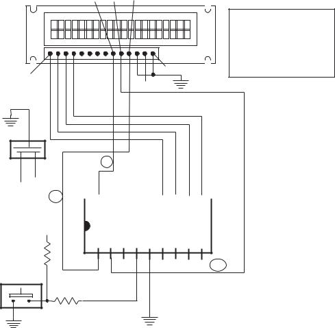
In the circuit of Figure 13-4, three control lines are wired between the microcontroller and the LCD. The line designations are shown inside ovals. The R/W line is not necessary, since it is possible to devise a system that does not read LCD data. In spite of this, the R/W line is not included since it allows reading the busy flag in synchronizing operations. Table 13.5 shows the control and data connections for the circuit in Figure 13-4.
Table 13.5
Connections for 16F84/LCD 8-bit Data Mode Circuit
16F84 |
|
LCD |
LINE |
|
PIN |
PORTBIT |
PIN |
NAME |
FUNCTION |
|
|
|
|
|
1 |
A2 |
4 |
RS |
Select instruction/ |
|
|
|
|
data register |
2 |
A3 |
5 |
R/W |
Read/write select |
18 |
A1 |
6 |
E |
Enable signal |
13 |
B7 |
14 |
before |
Busy flag. |
6-13 |
B0-B7 |
7-14 |
Data |
Data lines |
13.3 LCD Programming
LCD programming is usually device-specific. Before attempting to write code, the programmer should become familiar with the circuit wiring diagram, the set up parameters, and the specific hardware requirements. It is risky to make assumptions that a specific device conforms exactly to the HD44780 interface since often a style sheet contains specifications that are not in strict conformance with the standard. In addition to the PIC set up and initialization functions, code to display a simple text message on the LCD screen consists of the following display-related functions:
1.Define the required constants, variables, and buffers.
2.Set up and initialize ports used by the LCD.
3.Initialize the LCD to circuit and software specifications.
4.Store text in PIC text buffer.
5.Select DDRAM start address on LCD.
6.Display text by transferring characters in PIC text buffer to LCD DDRAM.
If the LCD display consists of multiple lines, then the previous steps 4, 5, and 6 are repeated for each line. LCD initialization and display operations vary according to whether the interface is 4- or 8-bits and whether the code uses delay loops or busy flag monitoring to synchronize operations. All of these variations are considered in the examples in this chapter.
13.3.1 Defining Constants and Variables
In any program, defining and documenting constants and fixed parameters should be done centrally, rather than hard-coded through the code. Centralizing the elements that are variable under different circumstances makes it possible to adapt code to circuit and hardware changes.
288 |
Chapter 13 |
Two common ways are available for defining constants: the C-like #define directive and the equ (equate) directive. In most cases, it is a matter of personal preference which is used, but a general guideline is to use the #define statement to create literal constants; that is, constants that are not associated with program registers or variables. The equ directive is then used to define registers, flags, and local variables.
According to this scheme, an LCD display driver program could use #define statements to create literals that are related to the wiring diagram or the specific LCD values obtained from the data sheet, such as the DDRAM addresses for each display line, as in the following code fragment:
;=====================================================
; |
constant definitions |
; |
for PIC-to-LCD pin wiring and LCD line addresses |
;=====================================================
#define E_line 1 |
;| |
|
#define RS_line 2 |
;| — from wiring diagram |
|
#define RW_line 3 |
;| |
|
; LCD line addresses (from LCD data sheet) |
||
#define LCD_1 |
0x80 |
; First LCD line constant |
#define LCD_2 |
0xc0 |
; Second LCD line constant |
By the same token, the values associated with PIC register addresses and bit flags are defined using equ, as follows:
;=====================================================
; PIC register equates
;=====================================================
porta |
equ |
0x05 |
portb |
equ |
0x06 |
fsr |
equ |
0x04 |
status |
equ |
0x03 |
indf |
equ |
0x00 |
z |
equ |
2 |
One advantage of this scheme is that constants are easier to locate, since they are grouped by device. Those for the LCD are in #define directives area and those for the PIC hardware in an area of equ directives.
There are also drawbacks to this approach, since symbols created in #define directive are not available for viewing in the MPLAB debuggers. However, if the use of the #define directive is restriced to literal constants, then their viewing during a debugging session is not essential.
MPLAB also supports the constant directive for creating a constant symbol. Its use is identical to the equ directive but the latter is more commonly found in code.
LCD Interfacing and Programming |
289 |
Using MPLAB Data Directives
Often a program needs to define a block of sequential symbols and assign to each one a corresponding name. In the PIC 16f84, the address space allocated to general purpose registers allocated by the user is of 68 bytes, starting at address 0x0c. One possible way of allocating user-defined registers is to use the equ directive to assign addresses in the PIC SRAM space:
Var1 |
equ |
0x0c |
|
|
Var2 |
equ |
0x0d |
|
|
Var3 |
equ |
0x0e |
|
|
Buf1 |
equ |
0x0f |
; |
10-byte buffer space |
Var4 |
equ |
0x19 |
; |
Next variable |
Although this method is functional, it depends on the programmer calculating the location of each variable in the PIC’s available SRAM space. Alternatively, MPLAP provides a cblock directive that allows defining a group of consecutive sequential symbols while referring only to the address of the first element in the group. If no address is entered in cblock, then the assembler assigns the address. This address is one higher than the final address in the previous cblock. Each cblock ends with the endc directive. The following code fragment showing the use of the cblock directive is from one of the sample programs for this chapter.
;=====================================================
; |
variables in PIC RAM |
;=====================================================
;Reserve 16 bytes for string buffer cblock 0x0c
strData
endc
;Leave 16 bytes and continue with local variables
cblock 0x1d |
; Start of block |
count1 |
; Counter # 1 |
count2 |
; Counter # 2 |
count3 |
; Counter # 3 |
pic_ad |
; Storage for start of text area |
|
; (labeled strData) in PIC RAM |
J |
; counter J |
K |
; counter K |
index |
; Index into text table |
endc |
|
Note in the preceding code fragment, the allocation for the 16-byte buffer space named strData is ensured by entering the corresponding start address in the second cblock. The PIC microcontrollers do not contain a directive for reserving memory areas inside cblock, although the res directive can be used to reserve memory for individual variables.
290 |
Chapter 13 |
13.3.2 LCD Initialization
LCD initialization depends on the specific hardware in use and on the circuit wiring. Information about the specific LCD can be obtained from the device’s data sheet. Sometimes, the data sheet includes examples of initialization values for different conditions and even code listings. The information is usually sufficient to ensure correct initialization.
A word of warning: the popular LCD literature available online often contains initialization “myths” for specific components requiring that a certain mystery code be used for no documented reason, or that a certain function be repeated a given number of times. The programmer should make sure that the code is rational and that every operation is actually required and documented.
Before the LCD initialization commands are used it is necessary to set the communications lines correctly. The E line should be low, the RS line should be low for command, and the R/W line (if connected) should be low for write mode. After the lines are set accordingly, there should be a 125ms delay. Note that at this point, the LCD busy flag is not yet reliable. The following code fragment shows the processing:
bcf |
porta,E_line |
; E line low |
||
bcf |
porta,RS_line |
; RS line low for command |
||
bcf |
porta,RW_line |
; |
Write |
mode |
call |
delay_125 |
; |
delay |
125 microseconds |
The procedure delay_125 in the previous code fragment is described later in this chapter.
Function Set Command
Function set is the first initialization command sent to the LCD. The command determines whether the display font consists of 5 x 10 or 5 x 7 pixels. The latter is by far the more common. It determines the duty cycle, which is typically 1/8 or 1/11 for sin- gle-line displays and 1/16 for multiple lines. The interface width is also determined in the Function Set command. It is 4-bits or 8-bits. The following code fragment shows the commented code for the Function Set command:
;***********************|
; |
Function Set |
|
| |
|
|
|
|
|
;***********************| |
|
|
|
|
|
|||
|
movlw |
0x38 |
; 0 0 1 1 1 0 0 0 (FUNCTION SET) |
|||||
|
|
|
; |
| | | |__ font select: |
||||
|
|
|
; |
| | | |
|
1 |
= 5x10 |
in 1/8 or 1/11 |
|
|
|
; |
| | | |
|
0 |
= 1/16 |
dc |
|
|
|
; |
| | |___ |
Duty cycle select |
|||
|
|
|
; |
| | |
|
0 |
= 1/8 or 1/11 |
|
|
|
|
; |
| | |
|
1 |
= 1/16 |
(multiple ines) |
|
|
|
; |
| |___ Interface width |
||||
|
|
|
; |
| |
0 |
= 4 bits |
|
|
|
|
|
; |
| |
1 |
= 8 bits |
|
|
|
|
|
; |
|___ FUNCTION SET |
COMMAND |
|||
LCD Interfacing and Programming |
291 |
|
movwf |
portb |
|
call |
pulseE ;pulse E line to force LCD command |
|
In the preceding code fragment, the LCD is initialized to multiple lines, 5 x 7 font, and 8-bit interface, as in the program LCDTest1 found in the book’s online software package.
The procedure named pulseE sets the E line bit off and on to force command recognition by the LCD. The procedure is listed and described later in the chapter.
Display Off
Some initialization routines in LCD documentation and data sheets require that the display be turned off following the Function Set command. If so, the Display Off command is executed as follows:
;***********************|
; |
Display Off |
| |
|
|
|
|
;***********************| |
|
|
|
|
||
|
movlw |
0x08 |
; 0 0 0 0 1 0 0 |
0 (DISPLAY ON/OFF) |
||
|
|
|
; |
| | | |
|___ Blink character at |
|
|
|
|
; |
| | | |
| |
Cursor |
|
|
|
; |
| | | |
|
1 = on, 0 = off |
|
|
|
; |
| | |___ Curson on/off |
||
|
|
|
; |
| | |
|
1 = on, 0 = off |
|
|
|
; |
| |____ Display on/off |
||
|
|
|
; |
| |
|
1 = on, 0 = off |
|
|
|
; |
|____ |
COMMAND BIT |
|
|
movwf |
portb |
|
|
|
|
|
call |
pulseE |
; pulse E line to force LCD command |
|||
Display and Cursor On
Whether or not the display is turned off, it must be turned on first. Also code must select if the cursor is on or off, and whether the character at the cursor position is to blink. The following command sets the cursor and the display on and the character blink off:
;***********************|
; Display and Cursor On |
;***********************|
movlw |
0x0e |
; 0 0 0 0 1 1 1 |
0 (DISPLAY ON/OFF) |
||
|
|
; |
| | | |
|___ |
Blink character at |
|
|
; |
| | | |
| |
cursor |
|
|
; |
| | | |
|
1 = on, 0 = off |
|
|
; |
| | |___ Curson on/off |
||
|
|
; |
| | |
1 |
= on, 0 = off |
|
|
; |
| |____ Display on/off |
||
|
|
; |
| |
1 = on, 0 = off |
|
|
|
; |
|____ |
COMMAND BIT |
|
292 |
Chapter 13 |
movwf |
portb |
call |
pulseE ; pulse E line to force LCD command |
Set Entry Mode
The Entry Mode Command sets the direction of cursor movement or display shift mode. Normally, the display is set to the increment mode when writing in the Western European languages. The Entry Mode command controls display shift. If enabled, the displayed characters appear to scroll. This mode is used to simulate an electronic billboard effect by storing more than one line of characters in DDRAM and then scrolling the characters left-to-right. The following code sets entry mode to increment mode and no shift:
;***********************|
; |
Set Entry Mode |
| |
|
|
|
;***********************| |
|
|
|||
|
movlw |
0x06 |
; 0 0 0 0 0 1 1 0 (ENTRY MODE SET) |
||
|
|
|
; |
| | |___ display shift |
|
|
|
|
; |
| | |
1 = shift |
|
|
|
; |
| | |
0 = no shift |
|
|
|
; |
| |____ cursor increment |
|
|
|
|
; |
| |
mode |
|
|
|
; |
| |
1 = left-to-right |
|
|
|
; |
| |
0 = right-to-left |
|
|
|
; |
|___ COMMAND BIT |
|
|
movwf |
portb |
;00000110 |
|
|
|
call |
pulseE |
|
|
|
Operations that read or write to CGRAM and operations that read DDRAM do not shift the display.
Cursor and Display Shift
These commands determine whether the cursor or the display shift according to the selected mode. Shifting the cursor or the display provides a software mechanism for making DDRAM corrections or for retrieving display data at specific DDRAM locations. The four available options appear in Table 13.4 previously in this chapter. The following instructions set the cursor to shift right and disable display shift:
;***********************|
; Cursor/Display Shift |
;***********************|
movlw |
0x14 |
; 0 0 0 1 0 1 0 |
0 (CURSOR/DISPLAY |
|
|||
|
|
; |
| | | | |
| |
SHIFT) |
|
|
|
|
; |
| | | |_|___ |
don’t care |
|
||
|
|
; |
| |_|__ |
cursor/display shift |
|||
|
|
; |
| |
00 |
= |
cursor shift |
left |
|
|
; |
| |
01 |
= |
cursor shift |
right |
|
|
; |
| |
10 |
= |
cursor and display |
|
|
|
; |
| |
|
|
shifted left |
|
LCD Interfacing and Programming |
|
|
293 |
; |
| |
11 = |
cursor and display |
; |
| |
|
shifted right |
; |
|___ COMMAND |
BIT |
|
movwf portb ;0001 1111
call pulseE
Clear Display
The final initialization command is usually one to clear the display. It is entered as follows:
;***********************| |
||
; |
Clear Display |
| |
;***********************| |
||
movlw |
0x01 |
; 0 0 |
0 0 0 0 0 1 (CLEAR DISPLAY) |
|
|
; |
|___ COMMAND BIT |
movwf |
portb |
;0000 |
0001 |
call |
pulseE |
|
|
call |
delay_5 |
;delay 5 milliseconds after init |
|
Note that the last command is followed by a 5ms delay. The delay procedure delay_5 is listed and described later in this chapter.
13.3.3 Auxiliary Operations
Several support routines are required for effective text display in LCD devices. These include time delay routines for timed access, a routine to pulse the E line in order to force the LCD to execute a command or to read or write text data, routines to read the busy flag when this is the method used for processor/LCD synchronization, and routines to merge data with port bits so as to preserve the status of port lines not being addressed by code.
Time Delay Routine
There are several ways of producing time delays in PIC microcontroller. The Bibliography lists a title by David Benson devoted almost entirely to timing and counting routines. The present concern is quite simple: to develop a software routine that ensures the time delay that must take place in LCD programming, as shown in Table 13.3.
One mechanism for producing time delays in PIC programming is by means of the TIMER0 module, a built-in 8-bit timer counter. Once enabled, Port-A pin 4, labeled the TOCKI bit and associated with file register 01 (TMR0), is used to time processor operations. In the particular case of LCD timing routines, using the TIMER0 module seems somewhat of an overkill, in addition to the fact that it requires the use of a Port-A line which is often required for other purposes.
Alternatively, timing routines that serve the purpose at hand can be developed using simple delay loops. In this case, no port line is sacrificed and coding is considerably simplified. These routines are generically labeled software timers, in contrast with the hardware timers that depend on the PIC timer/counter device described previously. Software timers provide the necessary delay by means of program loops;
294 |
Chapter 13 |
that is, by wasting time. The length of delay provided by the routine depends on the execution time of each instruction and on the number of repeated instructions.
Instructions on the PIC 16f84 consume four clock cycles. If the processor clock is running at 4 MHz, then one fourth of 4 MHz is the execution time for each instruction, which is 1 µs. So if each instructions requires 1 µs, repeating 1000 instructions produces a delay of 1 ms. The following routines provide convenient delays for LCD interfacing:
;=======================
;Procedure to delay
;125 microseconds ;======================= delay_125mics:
movlw |
D’42’ |
; Repeat |
42 machine |
cycles |
movwf |
count1 |
; Store value in counter |
||
repeat: |
|
|
|
|
decfsz |
count1,f |
; Decrement counter |
(1 cycle) |
|
goto |
repeat |
; Continue if not 0 |
(2 cycles) |
|
|
|
; 42 * 3 |
= 126 |
|
return |
|
; End of |
delay |
|
;======================= |
|
|
|
|
;Procedure to delay
;5 milliseconds ;======================= delay_5ms:
movlw |
D’41’ |
; Counter = 41 |
|
movwf |
count2 |
; Store in |
variable |
delay: |
|
|
|
call |
delay_125mics |
; Delay 41 |
microseconds |
decfsz |
count2,f |
; 41 times |
125 = 5125 ms. |
|
|
; or approximately 5 ms |
|
goto |
delay |
|
|
return |
|
; End of delay |
|
Actually, the delay loop of the procedure named delay_5ms is not exactly the product of 41 iterations times 125 µs, since the instruction to decrement the counter and the goto to the label delay are also inside the loop. Three instruction cycles must be added to those consumed by the delay_125mics procedure. This results in a total of 41 * 3 or 123 instruction cycles that must be added to the 5,125 consumed by delay_125mics. In fact, there are several other minor delays by the instructions to initialize the counters that are not included in the calculation. In reality, the delay loops required for LCD interfacing need not be exact, as long as they are not shorter than the recommended minimums.
For calculating software delays in the 16f84, the instruction execution time is determined by an external clock either in the form of an oscillator crystal, a resonator, or an RC oscillator furnished in the circuit. The PIC 16f84A is available in various processor speeds, from 4MHz to 20MHz. These speeds describe the maximum ca-
LCD Interfacing and Programming |
295 |
pacity of the PIC hardware. The actual instruction speed is determined by the clocking device, so a 20 MHZ 16f84A using a 4 MHz oscillator effectively runs at 4 MHz.
Pulsing the E Line
The LCD hardware does not recognize data as it is placed in the input lines. When the various control and data pins of the LCD are connected to ports in the PIC and data is placed in the port bits, no action takes place in the LCD controller. In order for the controller to respond to commands or to perform read or write operations, it must be activated by pulsating (or strobing) the E line. The pulsing or strobing mechanism requires that the E line be kept low and then raised momentarily. The LCD checks the state of its lines on the raising edge of the E line. Once the command has completed, the E line is brought low again. The following code fragment pulses the E line in the manner described.
;========================
; pulse E line
;========================
pulseE
bsf |
porta,E_line |
; |
pulse |
E line |
bcf |
porta,E_line |
|
|
|
call |
delay_125mics |
; |
delay |
125 microseconds |
return |
|
|
|
|
Note that the listed routine includes a 125µs delay following the pulsing operation. This delay is not part of the pulse function but is required by most LCD hardware. Some pulse functions in the popular PIC literature include a no operation opcode (nop) between the commands to set and clear the E line. In most cases this short delay does not hurt, but some LCDs require a minimum time lapse during the pulse and will not function correctly if the nop is inserted in the code.
Reading the Busy Flag
Synchronization between LCD commands and between data access operations is based on time delay loops or on reading the LCD busy flag. The busy flag, which is in the same pin as the bit 7 data line, is read clear when the LCD is ready to receive the next command, read, or write operation and is set if the device is not ready. By reading the state of the busy flag, code can accomplish more effective synchronization than with time delay loops. The sample program named LCDTest2, in the book’s online software package, performs LCD display using the busy flag method. The following procedure shows busy flag synchronization:
;========================
;busy flag test routine ;========================
;Procedure to test the HD44780 busy flag
;Execution returns when flag is clear busyTest:
movlw |
b’11111111’ |
; |
All lines to input |
tris |
portb |
|
; in port B |
bcf |
porta,RS_line |
; |
RS line low for control |
296 |
|
|
|
Chapter 13 |
bsf |
porta,RW_line |
; Read mode |
|
|
bsf |
porta,E_line |
; E line |
high |
|
movf |
portb,w |
; Read port |
B into W |
|
|
|
; Port B |
bit 7 is busy flag |
|
bcf |
porta,E_line |
; E line |
low |
|
andlw |
0x80 |
; Test bit 7, high is busy |
||
btfss |
status,z |
; Test zero |
bit in STATUS |
|
goto |
busyTest |
; Repeat |
if |
set |
;At this point busy flag is clear
;Reset R/W line and port B to output
bcf |
porta,RW_line |
; |
Clear R/W |
line |
movlw |
b’00000000’ |
; |
All lines |
to output |
tris |
portb |
|
; in port B |
|
return |
|
|
|
|
Note that testing the busy flag requires setting the LCD in read mode, which in turn requires implementing a connection between a PIC port and the R/W line. Also that the listed procedure contains no safety mechanism for detecting a hardware error condition in which the busy flag never clears. If such were the case, the program would hang in a forever loop. To detect and recover from this error the routine would have to include an external timing loop or some other means of recovering a possible hardware error.
Bit Merging Operations
Often, PIC/LCD circuits do not use all of the lines in an individual port. In this case the routines that manipulate PIC/LCD port access should not change the settings of other port bits. This situation is not exclusive to LCD interfacing; the discussion that follows has many other applications in PIC programming.
A processing routine can change one or more port lines without affecting the remaining ones. For example, an application that uses a 4-bit interface between the PIC and the LCD typically leaves four unused lines in the access port, or uses some of these lines for interface connections. In this case, the programming problem can be described as merging bits of the data byte to be written to the port and some existing port bits. One operand is the access port value and the other one is the new value to write to this port. If the operation at hand uses the four high-order port bits, then its four low-order bits must be preserved. The logic required is simple: AND the corresponding operands with masks that clear the unneeded bits and preserve the significant ones, then OR the two operands. The following procedure shows the required processing:
;=================
;merge bits ;=================
;Routine to merge the 4 high-order bits of the
;value to send with the contents of port B
;so as to preserve the 4 low-bits in port B
;Logic:
;AND value with 1111 0000 mask
LCD Interfacing and Programming |
297 |
;AND port B with 0000 1111 mask
;At this point low nibble in value and high
;nibble in port B are all 0 bits:
; |
value = vvvv 0000 |
; |
port B = 0000 bbbb |
;OR value and port B resulting in:
; |
vvvv bbbb |
;ON ENTRY:
;w contain value bits
;ON EXIT:
;w contains merged bits
merge4:
andlw |
b’11110000’ |
; ANDing with |
0 clears |
the |
|
|
; bit. ANDing |
with 1 preserves |
|
|
|
; the original value |
|
|
movwf |
store2 |
; Save result |
in variable |
|
movf |
portb,w |
; port B to w |
register |
|
andlw |
b’00001111’ |
; Clear high nibble in |
port b |
|
|
|
; and preserve low nibble |
||
iorwf |
store2,w |
; OR two operands in w |
|
|
return |
|
|
|
|
Note that this particular example refers to merging two operand nibbles. The code can be adapted to merge other size bit-fields by modifying the corresponding masks. For example, the following routine merges the high-order bit of one operand with the seven low-order bits of the second one:
;Routine to merge the high-order bit of the first operand with
;the seven low-order bits of the second operand
;ON ENTRY:
;w contains value bits of first operand
;port b is the second operand
merge1:
andlw |
b’10000000’ |
; ANDing |
with |
0 clears the |
|
|
; bit. ANDing |
with 1 preserves |
|
|
|
; the original value |
||
movwf |
store2 |
; Save result |
in variable |
|
movf |
portb,w |
; port B |
to w |
register |
andlw |
b’01111111’ |
; Clear high-order bit in |
||
|
|
; port b |
and preserve the |
|
|
|
; seven low order bits |
||
iorwf |
store2,w |
; OR two |
operands in w |
|
return |
|
|
|
|
Popular PIC literature describes routines to merge bit fields by assuming certain conditions in the destination operand, then testing the first operand bit to determine if the assumed condition should be preserved or changed. This type of operation is sometimes called “bit flipping,” for example:
298 |
Chapter 13 |
flipBit7:
;Code fragment to test the high-order bit in the variable named
;oprnd1 and preserve its status in the register variable portb
bcf |
portb,7 |
; Assume oprnd1 bit |
is |
reset |
|
btfsc |
oprnd1,7 |
; Test operand bit and |
skip if |
||
|
|
; |
clear (assumption |
valid) |
|
bsf |
portb,7 |
; |
Set bit if necessary |
|
|
return |
|
|
|
|
|
The logic in bit-flipping routines contains one critical flaw: if the assumed condition is false then the second operand is changed improperly, even if for only a few microseconds. However, the incorrect value can produce errors in execution if it is used by another device during this period. Since there is no such objection to the merge routines based on masking, the programmer should always prefer them.
13.3.4 Text Data Storage and Display
Text display operations require some way of generating the ASCII characters that are to be stored in DDRAM memory. Although the PIC Assembler contains several operators to generate ASCII data in program memory, there is no convenient way of storing a string in the General Purpose register area. Even if this was possible, SRAM is typically in short supply and text strings gobble up considerable data space.
Several possible approaches are available. The most suitable one depends on the total string length to be generated or stored, whether the strings are reused in the code, and other program-related circumstances. In this sense, short text-strings can be produced character-by-character and sent sequentially to DDRAM memory by placing the characters in the corresponding port and pulsing the E line.
The following code fragment consecutively displays the characters in the word
“Hello.” Code assumes that the command to set the Address register has been entered previously:
; Generate characters and send directly to DDRAM
movlw |
‘H’ |
; ASCII for H in w |
movwf |
portb |
; Store code in port B |
call |
pulseE |
; Pulse E line |
movlw |
‘e’ |
; Continues |
movwf |
portb |
|
call |
pulseE |
|
movlw |
‘l’ |
|
movwf |
portb |
|
call |
pulseE |
|
movlw |
‘l’ |
|
movwf |
portb |
|
call |
pulseE |
|
movlw |
‘o’ |
|
movwf |
portb |
|
call |
pulseE |
|
call |
delay_5 |
|
LCD Interfacing and Programming |
299 |
Note in the preceding fragment, the code assumes that the LCD has been initialized to automatically increment the Address register left-to-right. For this reason, the Address register is bumped to the next address with each port access.
Generating and Storing a Text String
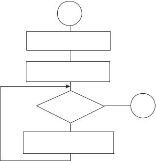
An alternative approach suitable for generating and displaying longer strings consists of storing the string data in a local variable (sometimes called a buffer) and then transferring the characters, one by one, from the buffer to DDRAM. This kind of processing has the advantage of allowing the reuse of the same string and the disadvantage of using up scarce data memory. The logic for one possible routine consists of first generating and storing in PIC RAM the character string, then retrieving the characters from the PIC RAM buffer and displaying them. The character generation and storage logic is shown in Figure 13-5.
START
Buffer pointer = 0
Get character using generator
|
YES |
Character = 0 |
END |
? |
|
NO
Store character in buffer
Bump buffer pointer
Figure 13-5 Flowchart for String Generation Logic
The processing is demonstrated in the following procedure.
;===============================
;first text string procedure ;=============================== storeMN:
;Procedure to store in PIC RAM buffer the message
;contained in the code area labeled msg1
;ON ENTRY:
;variable pic_ad holds address of text buffer
;in PIC RAM
300 |
Chapter 13 |
;w register hold offset into storage area
;msg1 is routine that returns the string characters
;and a zero terminator
;index is local variable that hold offset into
;text table. This variable is also used for
;temporary storage of offset into buffer
;ON EXIT:
;Text message stored in buffer
;
;Store offset into text buffer (passed in the w register)
;in temporary variable
movwf |
index |
|
; Store w in index |
; Store base address of text buffer in fsr |
|||
movf |
pic_ad,w ; |
first display RAM address to W |
|
addwf |
index,w |
; |
Add offset to address |
movwf |
fsr |
; |
W to FSR |
; Initialize index for text string access |
|||
movlw |
0 |
; |
Start at 0 |
movwf |
index |
; |
Store index in variable |
; w still = 0 |
|
|
|
get_msg_char: |
|
|
|
call |
msg1 |
; |
Get character from table |
; Test for zero terminator |
|
||
andlw |
0x0ff |
|
|
btfsc |
status,z ; |
Test zero flag |
|
goto |
endstr1 |
; |
End of string |
;ASSERT: valid string character in w
;store character in text buffer (by fsr)
movwf |
indf |
; store in buffer by fsr |
|
incf |
fsr,f |
; increment buffer pointer |
|
; Restore table character counter from variable |
|||
movf |
index,w |
; Get value into w |
|
addlw |
1 |
; Bump to next character |
|
movwf |
index |
; Store table index in variable |
|
goto |
get_msg_char |
; Continue |
|
endstr1: |
|
|
|
return
; Routine for returning message stored in program area msg1:
addwf |
PCL,f |
; Access table |
retlw |
‘M’ |
|
retlw |
‘i’ |
|
retlw |
‘n’ |
|
retlw |
‘n’ |
|
retlw |
‘e’ |
|
retlw |
‘s’ |
|
retlw |
‘o’ |
|
retlw |
‘t’ |
|
LCD Interfacing and Programming |
301 |
|
retlw |
‘a’ |
|
retlw |
0 |
; terminator character |
The auxiliary procedure named msg1, listed in the preceding code fragment, performs the character-generator function by producing each of the ASCII characters in the message string. Since a retlw instruction is necessary for each character, one instruction space in program memory is used for each character generated, plus a final binary zero for the string terminator.
Displaying the Text String
Once the string is stored in a local buffer, it is displayed by moving each ASCII code from the buffer into LCD DDRAM. Here again, we assume that the LCD has previously been set to the auto increment mode and that the Address register has been properly initialized with the corresponding DDRAM address. The following procedure demonstrates initialization of the DDRAM Address register to the value defined in the constant named LCD_1:
;========================
;Set Address register
;to LCD line 1 ;========================
;ON ENTRY:
;Address of LCD line 1 in constant LCD_1
line1:
bcf |
porta,E_line |
; E line low |
bcf |
porta,RS_line |
; RS line low, set up for |
|
|
; control |
call |
delay_125 |
; delay 125 microseconds |
; Set to second display line |
|
|
Movlw |
LCD_1 |
; Address and command bit |
movwf |
portb |
|
call |
pulseE |
; Pulse and delay |
; Set RS line for data |
|
|
bsf |
porta,RS_line |
; Set up for data |
call |
delay_125mics |
; Delay |
return |
|
|
Once the Address register has been set up, the display operation consists of transferring characters from the PIC RAM buffer into LCD DDRAM. The following procedure can be used for this:
;=============================
;LCD display procedure ;=============================
;Sends 16 characters from PIC buffer, with address stored
;in variable pic_ad, to LCD line previously selected display16:
;Set up for data
bcf |
porta,E_line |
; E line low |
302 |
|
|
Chapter 13 |
bsf |
porta,RS_line |
; RS line low for control |
|
call |
delay_125 |
; Delay |
|
; Set up counter for 16 characters |
|||
movlw |
D’16’ |
|
; Counter = 16 |
movwf |
count3 |
|
|
; Get display address from local variable pic_ad |
|||
movf |
pic_ad,w ; First display RAM address to W |
||
movwf |
fsr |
|
; W to FSR |
getchar: |
|
|
|
movf |
indf,w |
; get character from display RAM |
|
|
|
; location pointed to by file select |
|
|
|
; register |
|
movwf |
portb |
|
|
call |
pulseE |
;send data to display |
|
; Test for 16 characters displayed |
|||
decfsz |
count3,f ; Decrement counter |
||
goto |
nextchar ; Skipped if done |
||
return |
|
|
|
nextchar: |
|
|
|
incf |
fsr,f |
|
; Bump pointer |
goto |
getchar |
|
|
Note the procedure display16, previously listed, assumes that the address of the local buffer is stored in a variable name pic_ad. This allows reusing the procedure to display text stored at other locations in PIC RAM.
The previously listed procedures demonstrate just one of many possible variations on this technique. Another approach is to store the characters directly in DDRAM memory as they are produced by the message-returning routine, thus avoiding the display procedure entirely. In this last case, the programming saves some data memory space at the expense of having to generate the message characters each time they are needed. Which approach is the most suitable one depends on the application.
13.3.5 Data Compression Techniques
Circuits based on the parallel data transfer of eight data bits require eight devoted port lines. Assuming that three other lines are required for LCD commands and interfacing (RS, E, and R/W lines), then 11 PIC-to-LCD lines are needed, leaving two free port lines at the most, on an 16f84 microcontroller. Not many useful devices can make do with just two port lines. Several possible solutions allow compressing the data transfer function. The most obvious one is to use the 4-bit data transfer mode to free four port lines. Other solutions are based on dedicating logic components to the LCD function.
4-bit Data Transfer Mode
One possible solution is to use the capability of the Hitachi 44780 controller that allows a parallel interface using just four data paths instead of eight. The objections are that programming in 4-bit mode is slightly more convoluted and there is a very minor performance penalty. In 4-bit mode, data must be sent one nibble at a time, so execu-
LCD Interfacing and Programming |
303 |
tion is slower. Since the delay is required only after the second nibble, the execution time penalty for 4-bit transfers is not very large.
Many of the previously developed routines for 8-bit data mode can be reused without modification in the 4-bit mode. Others require minor changes, and there is one specific display procedure that must be developed ad hoc. The first required change is in the LCD initialization since bit 4 in the Function Set command must be clear for a 4-bit interface. The remaining initialization commands should require no further change, although it is a good idea to consult the data sheet for the LCD hardware in use.
Displaying data using a 4-bit interface consists of sending the high-order nibble followed by the low-order nibble, through the LCD 4-high-order data lines, usually labeled DB5 to DB7. The pulsing of line E follows the last nibble sent. It is usually the case in the 16f84 PIC that circuit wiring in the 4-bit mode uses four of five lines in Port-A, or four of eight lines in port B. Software must provide a way of reading and writing to the appropriate port lines, the ones used in the data transfer, without altering the value stored in the port bits dedicated to other uses. Bit merging routines, discussed in Section 13.3, are quite suitable for the purpose at hand.
The following procedures are designed to send the two nibbles of a data byte through the four high-order lines in port B. The auxiliary procedure named merge4 performs the bit-merging operation while the procedure named send8 does the actual write operation:
;========================
;send 2 nibbles in
;4-bit mode ;========================
;Procedure to send two 4-bit values to port B lines
;7, 6, 5, and 4. High-order nibble is sent first
;ON ENTRY:
;w register holds 8-bit value to send
send8:
movwf |
store1 |
; Save |
original value |
call |
merge4 |
; Merge with port B |
|
; Now w has merged byte |
|
|
|
movwf |
portb |
; w to |
port B |
call |
pulseE |
; Send |
data to LCD |
; High nibble is sent |
|
|
|
movf |
store1,w |
; Recover byte into w |
|
swapf |
store1,w |
; Swap |
nibbles in w |
call |
merge4 |
|
|
movwf |
portb |
|
|
call |
pulseE |
; Send |
data to LCD |
call |
delay_125 |
|
|
return |
|
|
|
;================= ; merge bits
304 |
Chapter 13 |
;=================
;Routine to merge the 4 high-order bits of the
;value to send with the contents of port B
;so as to preserve the 4 low-bits in port B
;Logic:
;AND value with 1111 0000 mask
;AND port B with 0000 1111 mask
;Now low nibble in value and high nibble in
;port B are all 0 bits:
; |
value = vvvv 0000 |
; |
port B = 0000 bbbb |
;OR value and port B resulting in:
; |
vvvv bbbb |
;ON ENTRY:
;w contain value bits
;ON EXIT:
;w contains merged bits
merge4:
andlw |
b’11110000’ |
; ANDing with |
0 clears |
the |
|
|
; bit. ANDing |
with 1 preserves |
|
|
|
; the original value |
|
|
movwf |
store2 |
; Save result |
in variable |
|
movf |
portb,w |
; port B to w |
register |
|
andlw |
b’00001111’ |
; Clear high nibble in |
port b |
|
|
|
; and preserve low nibble |
||
iorwf |
store2,w |
; OR two operands in w |
|
|
return |
|
|
|
|
The program named LCDTest3 in the book’s online software package is a demonstration using the 4-bit interface mode. Figure 13-6 shows a PIC/LCD circuit that is wired for the 4-bit data transfer mode.
Note in the circuit of Figure 13-6 that a total of six port lines remain unused. Two of these lines are in Port-A and four in Port-B.
Master/Slave Systems
To this point we have assumed that driving the LCD is one of the functions performed by the PIC microcontroller, which also executes the other circuit functions. In practice, such a scheme is rarely viable for two reasons: the number of interface lines required and the amount of PIC code space used up by the LCD driver routines. A more efficient approach is to dedicate a PIC exclusively to controlling the LCD hardware, while one or more other microcontrollers perform the main circuit functions. In this scheme, the PIC devoted to the LCD function is referred to as a slave while the one that sends the display commands is called the master.
LCD Interfacing and Programming |
|
305 |
E R/W RS |
|
|
|
|
HD44780 pin out |
|
1 |
GND |
|
2 |
DC +5v |
|
3 |
Contrast adjust |
|
4 |
RS (register select) |
HD44780 |
5 |
R/W (read/write select) |
|
6 |
E (signal enable) |
1 |
11-14 Data bits 4 to 7 |
|
|
||
14 |
|
|
+5 V |
|
|
4 MHz
Osc
E
+5 V
|
|
|
|
|
|
|
|
|
|
|
|
|
|
|
|
|
|
|
|
RS |
18 |
|
17 |
|
16 |
15 |
|
14 |
|
13 |
|
12 |
|
11 |
|
10 |
|
|
|
|
|
|
|
|
|
|
||||||||||
|
|
|
|
|
|
|
|
|
|
|
|
|
|
|
|
|
|
|
|
|
|
|
|
|
|
|
|
|
|
|
|
|
|
|
|
|
|
|
|
RA1 |
RA0 |
OSC1 OSC2 |
Vdd |
RB7 |
RB6 |
RB5 |
RB4 |
|||||||||
+5 V |
|
|
16F84 |
|
|
|
||
|
|
RA4/ |
|
|
|
|
|
|
RA2 |
RA3 |
T0Tkl |
MCLR |
Vss |
RB0/INT |
RB1 |
RB2 |
RB3 |
10 K |
2 |
3 |
4 |
5 |
6 |
7 |
8 |
9 |
1 |
||||||||
|
|
|
|
|
|
|
|
R/W |
RESET |
|
|
|
|
|
|
|
|
100 Ohms |
|
|
|
|
|
|
|
|
Figure 13-6 PIC/LCD Circuit for 4-bit Data Mode
When sufficient numbers of interface lines are available, the connection between master and slave can be simplified by using a parallel interface. For example, if four port lines are used to interconnect the two PICs, then 16 different command codes can be sent to the slave. The slave reads the communications lines much like it would read a multiple toggle switch. A simple protocol can be devised so that the slave uses these same interface lines to provide feedback to the master. For example, the slave sets all four lines low to indicate that it is ready for the next command, and sets them high to indicate that command execution is in progress and that no new commands can be received. The master, in turn, reads the communications lines to determine when it can send another command to the slave.
But using parallel communications between master and slave can be a self-defeating proposition, since it requires at least seven interface lines to be able