


Chapter 12
Timers and Counters
This chapter is about using the built-in timing and counting circuits on the 16F84. It relates to Chapter 11 since timing and counting operations can be set up to generate interrupts. The material also serves as background for Chapter 14, on serial communications, since these require precise pulses that are usually obtained through the timers.
12.0 The 16F84 Timer0 Module
One of the timers on the 16F84 PIC is known as the Timer0 module, the free-running timer, the timer/counter, or as TMR0. Timer0 is an internal 8-bit register that increments automatically with every PIC instruction cycle until the count overflows timer capacity. This takes place when the timer count goes from 0xff to 0x00. At that time, the timer restarts the count. The timer has the following characteristics:
1.A timer register that is readable and writeable by software
2.Can be powered by an external or internal clock
3.Timing edge for external clock can be selected
4.8-bit software programmable prescaler
5.Interrupt capability
6.Can be used as a timer or as a counter
12.0.1 Timer0 Operation
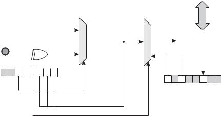
Timer operation can be assigned to the internal clock or to the PIC’s RA4/TOCKI pin. Bit 5 of the OPTION register (labeled TOCS) performs this selection. If TOCS is set, then the timer is linked to the RA4/TOCKI pin. In this mode, the timer is used as a counter. If TOCS is reset, then the timer uses the PIC’s instruction cycle clock signal. If an external source is selected by setting the TOCS bit, then bit 4 of the OPTION register (labeled TOSE) allows selecting whether the timer increments on the high-to-low or low-to-high transition of the signal on the RA4/TOCKI pin. As shown in Figure 12-1, bits 6 and 7 of the OPTION register are not used in configuring the Timer0 module.
241
242 |
Chapter 12 |
|
|
|
|
|
|
|
|
|
|
|
|
|
|
|
|
|
|
|
|
|
|
|
|
data bus |
||||
|
|
|
|
|
|
OSC/4 |
|
|
|
|
|
|
|
|
|
|
|
|
|
|
|
|
|
|
|
|
||
|
|
|
|
|
|
|
|
|
|
|
|
|
|
|
|
|
|
7 |
6 |
5 |
4 |
3 |
2 |
1 |
0 |
|
||
TOCKI |
|
|
|
|
|
|
|
|
|
|
|
|
|
|
|
|
|
|
|
TMR0 |
|
|||||||
|
|
|
|
|
|
|
|
|
|
|
|
|
|
|
|
|
|
|
|
|||||||||
|
|
|
|
|
|
|
|
|
|
|
|
|
|
|
|
|
|
|
|
|||||||||
|
|
|
|
|
|
|
|
|
|
|
|
|
|
|
|
GIE |
|
|
|
|
|
|
|
|
|
|
|
|
|
|
|
|
|
|
|
|
|
|
|
|
|
|
|
|
TOIE |
|
|||||||||||
|
|
|
|
|
|
|
|
|
|
|
|
|||||||||||||||||
|
|
|
|
|
|
|
|
|
|
|
|
|
|
|
|
|
|
|
|
|
|
|
|
|
||||
|
|
|
|
TOSE (Source edge select) |
TOCS |
|
|
|
|
|
|
TOIF (TMR0 interrupt) |
||||||||||||||||
|
|
|
|
|
|
|
|
|
|
|
|
|
|
|
|
|
|
|||||||||||
7 |
6 |
5 |
4 |
3 |
2 |
1 |
0 |
OPTION |
(Clock source select) |
|
|
|
|
|
|
|
|
|
|
|
||||||||
|
|
|
|
|
|
|
|
|
|
|
|
|
|
|
|
|
||||||||||||
7 |
6 |
5 |
4 |
3 |
2 |
1 |
0 |
INTCON |
PS2-PS0 (Prescaler)
PSA (Prescaler assignment)
Figure 12-1 Timer0 Block Diagram
When used as a timer, Timer0 can be visualized as a register that increments with every instruction cycle at ¼ the clock rate, without using the prescaler. In a PIC equipped with a 4 Mhz oscillator the timer register increments at a rate of one pulse per millisecond. Since there are eight bits in the counter register, the value stored is in the range 0 to 255 decimal. When the counter overflows the register is reset. Figure 12-1 is a simplified block diagram of the Timer0 hardware.
Timer0 Interrupt
Software can read the timer register directly or set up the timer to generate an interrupt at every transition from 0xff to 0x00. The timer register can be accessed in bank 0, offset 0x01. The timer interrupt is enabled by setting bit 5 (labeled TOIE) of the INTCON register. In this case the Global Interrupt Enable bit (labeled GIE) of INTCON register must also be set. Once the timer interrupt is enabled, the Timer Interrupt Flag, assigned to bit 2 of the INTCON Register and labled TOIF, is set on every overflow of the timer register. At that time an interrupt takes place. The TOIF bit (Timer0 flag) must be cleared by the interrupt handler so that the timer interrupt can take place again. Later in this chapter we develop a sample program that uses Timer0 as an interrupt source.
Timer0 Prescaler
The counter prescaler consists of the three low-order bits in the OPTION register. These bits allow selecting eight possible values that serve as a divisor for the counter rate. When the prescaler is disabled, the counter rate is one-fourth the processor’s clock speed. If the prescaler is set to the maximum value (255) then one of 255 clock signals actually reach the timer. Table 12-1 shows the prescaler settings and their action on the rate of the Timer0 module and the Watchdog Timer, covered later in this chapter.
Timers and Counters |
|
243 |
|
|
Table 12.1 |
|
|
|
Prescaled Bits Selected Rates |
|
|
|
|
|
|
BIT VALUE |
TMR0 RATE |
WDT RATE |
|
|
|
|
|
000 |
1:2 |
1:1 |
|
001 |
1:4 |
1:2 |
|
010 |
1:8 |
1:4 |
|
011 |
1:16 |
1:8 |
|
100 |
1:32 |
1:16 |
|
101 |
1:64 |
1:32 |
|
110 |
1:128 |
1:64 |
|
111 |
1:256 |
1:128 |
|
The prescaler can be assigned to either Timer0 or the Watchdog Timer, but not to both. If bit 3 of the OPTION register is set, then the prescaler is assigned to the Watchdog Timer if it is clear it is assigned to the Timer0 module.
12.1 Delays Using Timer0
The simplest application of the Timer0 module is as an instruction cycle counter in implementing delay loops. Applications in which the Timer0 register is polled directly are said to use a free running timer. There are two advantages of using free running timers over conventional delay loops: the prescaler provides a way of slowing down the count, and the delay is independent of the number of machine cycles in the loop body. In most cases, it is easier to implement an accurate time delay using the Timer0 module than by counting instruction cycles.
Calculating the time taken by each counter iteration consists of dividing the clock speed by four. For example, a PIC running on a 4 Mhz oscillator clock increments the counter every 1 Mhz. If the prescaler is not used, the counter register is incremented at a rate of 1 µs; the timer beats at a rate of 1,000,000 times per second. If the prescaler is set to the maximum divisor value (256) then each increment of the timer takes place at a rate of 1,000,000/256 µs, which is approximately 3.906 ms. Since this is the slowest possible rate of the timer in a machine running at 4 Mhz, it is often necessary to employ supplementary counters in order to achieve larger delays.
The fact that the timer register (Tmr0) is both readable and writeable makes possible some interesting timing techniques. For example, an application can set the Timer register to an initial value and then count until a predetermined limit is reached. For example, if the difference between the limit and the initial value is 100, then the routine counts 100 times the timer rate per beat. In another example, if a routine allows the timer to start from zero and count unrestrictedly, then when the count reaches the maximum value (0xff) the routine would have introduced a delay of 256 times the timer beat rate, as is the case in the previous example, in which a maximum value was used in the prescaler and the timer ran at a rate of 1,000,000 beats per second. Applying the prescaler, each timer beat takes place at a rate of 1,000,000/256, or approximately 3,906 timer beats per second. If we develop a routine that delays execution until the maximum value has been reached in the counter register, then the delay can be calculated by dividing the number of beats per second

244 |
Chapter 12 |
(3,906) by the number of counts in the delay loop. In this case, 3,906/256 results in a delay of approximately 15.26 iterations of the delay routine per second.
A general formula for calculating the number of timer beats per second is as follows:
T = C 4PR
where T is the number of clock beats per second, C is the system clock speed in Hz, P is the value stored in the prescaler, and R is the number of iterations counted in the TMR0 register. The range of both P and R in this formula is 1 to 256. Also, note that the reciprocal of T (1/T) gives the time delay, in seconds, per iteration of the delay routine.
12.1.1 Long Delay Loops
In the previous section we saw that even when using the largest possible prescaler and counting the maximum number of timer beats, the longest possible timer delay in a 4
Mhz system is approximately 1/15th of a second. Also consider that applications must sometimes devote the prescaler to the Watchdog Timer, which impedes its use in Timer0. Without the prescaler, the maximum delay is of approximately 3,906 timer beats per second. Applications that measure time in seconds or in minutes must find ways for keeping count of large numbers of repetitions of the timer beat.
In implementing counters for larger delays we have to be careful not to introduce round-off errors. For instance, in the previous example a timer cycles at the rate of 15.26 times per second. The closest integer to 15.26 is 15, so if we now set up a seconds counter that counts 15 iterations, the counter would introduce an error of approximately 2 percent.
Considering that in the previous example each iteration of the timer contains 256 individual beats, there are 3,906.25 individual timer beats per second at the maximum prescaled rate. So if we were to implement a counter to keep track of individual prescaled beats, instead of timer iterations, the count would proceed from 0 to
3,906 instead of from 0 to 15. Approximating 3,906.25 to the closest integer, 3,906, introduces a much smaller round-off error than approximating 15.26 with 15.
Finally, in this same example, we could eliminate the prescaler so that the timer beats at the clock rate, that is, at 1,000,000 beats per second. In this option, a counter that counts from 0 to 1,000,000 would have no intrinsic error due to round off.
Which solution is more adequate depends on the accuracy required by the application and the complexity tolerated. A timer counter in the range of 0 to 15 can be implemented in a single 8-bit register. A counter in the range 0 to 3,906 requires two bytes. One to count from 0 to 1,000,000 requires three bytes. Since arithmetic operations in the 16F84 are 8-bits, manipulating multiple-register counters requires more complicated processing.
Timers and Counters |
245 |
How Accurate the Delay?
The actual implementation of a delay routine based on multi-byte counters presents some difficulties. If the timer register (TMR0) is used to keep track of timer beats, then detecting the end of the count poses a subtle problem. Intuitively, our program could detect timer overflow by reading the TMR0 and testing the zero flag in the status register. Since the movf instruction affects the zero flag, one could be tempted to code:
wait: |
|
|
movf |
tmr0,w ; |
Timer value into w |
btfss |
status,z ; |
Was it zero? |
goto |
wait |
|
; If this point is reached TMR0 has overflowed
But there is a problem: the timer ticks as each instruction executes. Since the goto instruction takes two machine cycles, it is possible that the timer overflows while the goto instruction is in progress; therefore the overflow condition would not be detected. One possible solution found in the Microchip documentation is to check for less than a nominal value by testing the carry flag, as follows:
wait1:
movlw |
0x03 |
; 3 to w |
|
subwf |
tmr0,w ; |
Subtract w |
– TMR0 |
btfsc |
status,c ; |
Test carry |
|
goto |
wait1 |
|
|
One adjustment that is sometimes necessary in free running timers arises from the fact that when the TMR0 register is written, the count is inhibited for the following two instruction cycles. Software compensates for the skip by writing an adjusted value to the timer register. If the prescaler is assigned to Timer0, then a write operation to the timer register determines that the timer does not increment for four clock cycles.
The Black-Ammerman Method
A more elegant and accurate solution has been described by Roman Black in a Web article titled Zero-Error One Second Timer. Black credits Bob Ammerman with the suggestion of using Bresenham’s algorithm for creating accurate PIC timer periods. In the Black-Ammerman method, the counter works in the background, either by being polled or interrupt-driven, so the program can continue executing while the counter runs. In both cases, the timer-count value is stored in a 3-byte register decremented by the software.
In their interrupt-driven version, TMR0 generates an interrupt whenever the counter register overflows, that is, every 256th timer beat (assuming no prescaler). The interrupt handler routine decrements the mid-order register that holds the 3-byte timer count. This is appropriate since every unit in the mid-order register represents 256 units of the low-order counter, which in this case is the TMR0 register. If the mid-order register underflows when decremented, then the high-order one is decremented. If the high-order one underflows, then the count has reached zero and