


6 |
Chapter 1 |
Where P represents the power in watts, V is the voltage in volts, and I is the current in amperes. Ohm's Law can also be formulated in terms of voltage, current, and resistance as shown later in this chapter.
1.4 Electrical Circuits
An electrical network is an interconnection of electrical elements. An electrical circuit is a network in a closed loop, giving a return path for the current. A network is a connection of two or more simple elements, and may not necessarily be a circuit.
Although there are several types of electrical circuits they all have some of the following elements:
1.A power source, which can be a battery, alternator, etc., produces an electrical potential.
2.Conductors, in the form of wires or circuit boards, provide a path for the current.
3.Loads, in the form of devices such as lamps, motors, etc., use the electrical energy to produce some form of work.
4.Control devices, such as potentiometers and switches, regulate the amount of current flow or turn it on and off.
5.Protection devices, such as fuses or circuit breakers, prevent damage to the system in case of overload.
6.A common ground.
Figure 1-5 shows a simple circuit that contains all of these elements.
+
-
Figure 1-5 Simple Circuit
1.4.1 Types of Circuits
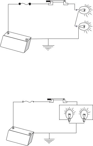
There are three common types of circuits: series, parallel, and series-parallel. The circuit type is determined by how the components are connected. In other words, by how the circuit elements, power source, load, and control and protection devices are interconnected. The simplest circuit is one in which the components offer a single current path. In this case, although the loads may be different, the amount of current flowing through each one is the same. Figure 1.6 shows a series circuit with two light bulbs.
Basic Electronics |
7 |
|||
|
|
|
|
|
|
|
|
|
|
|
|
|
|
|
|
|
|
|
|
+
-
Figure 1-6 Series Circuit
In the series circuit in Figure 1-6 if one of the light bulbs burn out, the circuit flow is interrupted and the other one will not light. Some Christmas lights are wired in this manner, and if a single bulb fails the whole string will not light.
In a parallel circuit there is more than one path for current flow. Figure 1-7 shows a circuit wired in parallel.
+
-
Figure 1-7 Parallel Circuit
In the circuit of Figure 1-7, if one of the light bulbs burns out, the other one will still light. Also, if the load is the same in each circuit branch, so will be the current flow in that branch. By the same token, if the load in each branch is different, so will be the current flow in each branch.
The series-parallel circuit has some components wired in series and others in parallel. Therefore, the circuit shares the characteristics of both series and parallel circuits. Figure 1-8 shows the same parallel circuit to which a series rheostat (dimmer) has been added in series.

8 |
|
|
|
Chapter 1 |
|
|
|
|
|
|
|
|
|
|
|
|
|
|
|
|
|
|
|
|
VARIABLE RESISTOR (DIMMER)
+
-
Figure 1-8 Series-Parallel Circuit
In the circuit of Figure 1-8 the two light bulbs are wired in parallel, so if one fails the other one will not. However, the rheostat (dimmer) is wired in series with the circuit, so its action affects both light bulbs.
1.5 Circuit Elements
So far we have represented circuits using a pictorial style. Circuit diagrams are more often used since they achieve the same purpose with much less artistic effort and are easier to read. Figure 1-9 is a diagrammatic representation of the circuit in Figure 1-8.
+
-
Figure 1-9 Diagram of a Series-Parallel Circuit
Certain components are commonly used in electrical circuits. These include power sources, resistors, capacitors, inductors, and several forms of semiconductor devices.

Basic Electronics |
9 |
1.5.1 Resistors
If the current flow from, say, a battery is not controlled, a short-circuit takes place and the wires can melt or the battery may even explode. Resistors provide a way of controlling the flow of current from a source. A resistor is to current flow in an electrical circuit as a valve is to water flow: both elements "resist" flow. Resistors are typically made of materials that are poor conductors. The most common ones are made from powdered carbon and some sort of binder. Such carbon composition resistors usually have a dark-colored cylindrical body with a wire lead on each end. Color bands on the body of the resistor indicate its value, measured in ohms and represented by the Greek letter ω. The color code for resistor bands can be found in Appendix A.
The potentiometer and the rheostat are variable resistors. When the knob of a potentiometer or rheostat is turned, a slider moves along the resistance element and reduces or increases the resistance. A potentiometer is used as a dimmer in the circuits of Figure 1-8 and Figure 1-9. The photoresistor or photocell is composed of a light sensitive material whose resistance decreases when exposed to light. Photoresistors can be used as light sensors.
1.5.2 Revisiting Ohm's Law
We have seen how Ohm's Law describes the relationship between voltage, current, and power. The law is reformulated in terms of resistance so as to express the relationship between voltage, current, and resistance, as follows:
In this case V represents voltage, I is the current, and R is the resistance in the circuit. Ohm's Law equation can be manipulated in order to find current or resistance in terms of the other variables, as follows:
V = I × R
Note that the voltage value in Ohm's Law refers to the voltage across the resistor, in other words, the voltage between the two terminal wires. In this sense the voltage is actually produced by the resistor, since the resistor is restricting the flow of charge much as a valve or nozzle restricts the flow of water. It is the restriction created by the resistor that forms an excess of charge with respect to the other side of the circuit. The charge difference results in a voltage between the two points. Ohm's Law is used to calculate the voltage if we know the resistor value and the current flow.
I = V
R
R = V
I

10 |
Chapter 1 |
V
V=IR
I R
V
I=V/R
I R
V
R=V/I
I R
Figure 1-10 Ohm's Law Pyramid
A popular mnemonics for Ohm's Law consists of drawing a pyramid with the voltage symbol at the top and current and resistance in the lower level. Then, it is easy to solve for each of the values by observing the position of the other two symbols in the pyramid, as shown in Figure 1-10.
1.5.3 Resistors in Series and Parallel
When resistors are in series the total resistance equals the sum of the individual resistances. The diagram in Figure 1-11 shows two resistors (R1 and R2) wired in series in a simple circuit.
R1 |
R2 |
+
-
Figure 1-11 Resistors in Series
In Figure 1-11 the total resistance (RT) is calculated by adding the resistance values of R1 and R2, thus, RT = R1 + R2.
In terms of water flow, a series of partially closed valves in a pipe add up to slow the flow of water.
Resistors can also be connected in parallel, as shown in Figure 1-12.

Basic Electronics |
11 |
|
R1 |
R2
+
-
Figure 1-12 Resistors in Parallel
When resistors are placed in parallel, the combination has less resistance than any one of the resistors. If the resistors have different values, then more current flows through the path of least resistance. The total resistance in a parallel circuit is obtained by dividing the product of the individual resistors by their sum, as in the formula:
RT = R1× R2
R1 + R2
If more than two resistors are connected in parallel, then the formula can be expressed as follows:
RT = |
|
|
|
|
1 |
|
|
|
|
|
1 |
|
+ |
1 |
|
+ |
1 |
... |
|
|
|
R1 |
R2 |
R3 |
|||||
|
|
|
|
|
|||||
Also note that the diagram representation of resistors in parallel can have different appearances. For example, the circuit in Figure 1-13 is electrically identical to the one in Figure 1-12.
R1 R2
+
-
Figure 1-13 Alternative Circuit of Parallel Resistors

12 |
Chapter 1 |
Figure 1-14 Resistors
Figure 1-14 shows several commercial resistors. The integrated circuit at the center of the image combines eight resistors of the same value. These devices are convenient when the circuit design calls for several identical resistors. The color-coded cylindrical resistors in the image are made of carbon
Appendix A contains the color codes used in identifying resistors whose surface area does not allow printing its value.
1.5.4 Capacitors
An element often used in the control of the flow of an electrical charge is a capacitor.
The name originated in the notion of a "capacity" to store charge. In that sense a capacitor functions as a small battery. Capacitors are made of two conducting surfaces separated by an insulator. A wire lead is usually connected to each surface. Two large metal plates separated by air would perform as a capacitor. More frequently capacitors are made of thin metal foils separated by a plastic film or another form of solid insulator. Figure 1-15 shows a circuit which contains both a capacitor and a resistor.
In Figure 1-15 charge flows from the battery terminals, along the conductor wire, onto the capacitor plates. Positive charges collect on one plate and negative charges on the other plate. The initial current is limited only by the resistance of the wires and by the resistor in the circuit. As charge builds up on the plates, charge repulsion resists the flow and the current is reduced. At some point the repulsive force from charge on the plates is strong enough to balance the force from charge on the battery, and the current stops.
+
-
Figure 1-15 Capacitor Circuit
Basic Electronics |
13 |
The existence of charges on the capacitor plates means there must be a voltage between the plates. When the current stops this voltage is equal to the voltage in the battery. Since the points in the circuit are connected by conductors, then they have the same voltage, even if there is a resistor in the circuit. If the current is zero, there is no voltage across the resistor, according to Ohm's law.
The amount of charge on the plates of the capacitor is a measure of the value of the capacitor. This "capacitance" is measured in farads (f), named in honor of the English scientist Michael Faraday.
The relationship is expressed by the equation:
C = Q
V
where C is the capacitance in farads, Q is the charge in Coulombs, and V is the voltage. Capacitors of one farad or more are rare. Generally capacitors are rated in microfarads (µf), one-millionth of a farad, or picofarads (pf), one-trillionth of a farad.
Consider the circuit of Figure 1-15 after the current has stabilized. If we now remove the capacitor from the circuit it still holds a charge on its plates. That is, there is a voltage between the capacitor terminals. In one sense, the charged capacitor appears somewhat like a battery. If we were to short-circuit the capacitor's terminals a current would flow as the positive and negative charges neutralize each other. But unlike a battery, the capacitor does not replace its charge. So the voltage drops, the current drops, and finally there is no net charge and no voltage difference anywhere in the circuit.
1.5.5 Capacitors in Series and in Parallel
Like resistors, capacitors can be joined together in series and in parallel. Connecting two capacitors in parallel results in a bigger capacitance value, since there is a larger plate area. Thus, the formula for total capacitance (CT) in a parallel circuit containing capacitors C1 and C2 is:
CT = C1 + C2
Note that the formula for calculating capacitance in parallel is similar to the one for calculating series resistance. By the same token, where several capacitors are connected in series the formula for calculating the total capacitance is:
CT = 1 + 11 + 1 ...
C1 C2 C3

14 |
Chapter 1 |
Figure 1-16 Assorted Commercial Capacitors
Note that the total capacitance of a connection in series is lower than for any capacitor in the series, considering that for a given voltage across the entire group there is less charge on each plate.
There are several types of commercial capacitors, including mylar, ceramic, disk, and electrolytic. Figure 1-16 shows several commercial capacitors.
1.5.6 Inductors
Inductors are the third type of basic circuit components. An inductor is a coil of wire with many windings. The wire windings are often made around a core of a magnetic material, such as iron. The properties of inductors are derived from magnetic rather than electric forces.
When current flows through a coil it produces a magnetic field in the space outside the wire. This makes the coil behave just like a natural, permanent magnet. Moving a wire through a magnetic field generates a current in the wire, and this current will flow through the associated circuit. Since it takes mechanical energy to move the wire through the field, then it is the mechanical energy that is transformed into electrical energy. A generator is a device that converts mechanical to electrical energy by means of induction. An electric motor is the opposite of a generator. In the motor electrical energy is converted to mechanical energy by means of induction.
The current in an inductor is similar to the voltage across a capacitor. In both cases it takes time to change the voltage from an initially high current flow. Such induced voltages can be very high and can damage other circuit components, so it is common to connect a resistor or a capacitor across the inductor to provide a current path to absorb the induced voltage. In combination inductors behave just like resistors: inductance adds in series. By the same token, parallel connection reduces induction. Induction is measured in henrys (h), but more commonly in mh, and µh.