

194 Chapter 10
ops_are_eq:
; Processing for the case OP1 = OP2l nop
nop
goto done
op2big:
; Processing for the case OP1 < OP2 nop
nop
done:
goto |
done |
end |
|
The Infamous PIC Carry Flag
In PIC programming, the effects on the carry flag are different in addition than in subtraction. During addition (addwf and addlw) the carry flag indicates a carry-out of the most significant bit of the result. In this case, C = 1 if there was a carry out, and C = 0 otherwise. However, in subtraction the carry flag is described in the Microchip documentation as behaving as an inverted borrow. This means that when two numbers are subtracted and the result is too big to fit in the destination operand, then the carry flag is clear. What this amounts to is that in PIC subtraction (sublw and subwf operations) the carry bit is set if there is no carry-out of the high-order bit. This unusual behavior is shown in the preceding code fragment.
10.2 Simple Circuits and Programs
In the following sections we describe very simple PIC-based circuits that can be assembled with few components on a breadboard. The corresponding programs exercise the circuit components. The beginner should not skip building these circuits and coding the programs since they demonstrate essential hardware and software elements.
As a learning experience, it is a good idea to reverse engineer the code in these sample programs. With the processor’s instruction set at hand, listed in Appendix C, proceed to follow the code one instruction at a time until you can understand every processing detail.
10.2.1 A Single LED Circuit
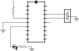
One of the simplest circuits consists of a single LED lamp wired to Port-B, line 0, of a 16F84A PIC, as shown in Figure 10-3.
The power source for the circuit in Figure 10-3 is not shown in the diagram. Typically, a battery source or an AC/DC converter and a voltage stabilizer circuit as in the one in Figure 10-2 are used.
A program to turn on the LED on Port-B, line 0, requires a few but essential processing operations. Code must perform the following operations:
Programming Essentials: Input and Output |
195 |
+5v |
|
1
2
R=10K
3
4
5
6
7
8
9
LED R=330Ohm
RA2
RA3
RA4/TOCKI
MCLR
Vss
16F84A
RB0/INT
RB1
RB2
RB3
18
RA1
Osc
17
RA0
16
OSC1
15
OSC2
14
Vdd +5v
13
RB7
12
RB6
11
RB5
10
RB4
Figure 10-3 Simple LED Circuit
1.Define and select processor (in this case 16F84A).
2.Link-in the corresponding include file (p16f84A.inc).
3.Select the oscillator type (here external resonator, _XT type).
4.Direct execution to the main label.
5.Initialize Port-B for output.
6.Set line 0 in Port-B high.
The entire program is as follows:
;File: LEDOn.asm
;Date: June 1, 2006
;Author: Julio Sanchez
;Processor: 16F84A
;
;Description:
;Turn on LED wired to Port-B, line 0 ;===========================
;switches ;===========================
;Switches used in __config directive:
; |
|
_CP_ON |
Code protection ON/OFF |
; * |
_CP_OFF |
|
|
; |
* |
_PWRTE_ON |
Power-up timer ON/OFF |
;_PWRTE_OFF
; |
_WDT_ON |
Watchdog |
timer ON/OFF |
|
; * _WDT_OFF |
|
|
|
|
; |
_LP_OSC |
Low power crystal |
occilator |
|
; * _XT_OSC |
External |
parallel |
resonator/crystal oscillator |
|
; |
_HS_OSC |
High speed crystal resonator (8 to 10 MHz) |
196 |
|
Chapter 10 |
; |
|
Resonator: Murate Erie CSA8.00MG = 8 MHz |
; |
_RC_OSC |
Resistor/capacitor oscillator |
;|
;|_____ * indicates setup values
processor |
16f84A |
include |
<p16f84A.inc> |
__config |
_XT_OSC & _WDT_OFF & _PWRTE_ON & _CP_OFF |
;========================================================
; variables in PIC RAM
;======================================================== ; None used ;========================================================
; m a i n p r o g r a m
;========================================================
org |
0 |
; start at address 0 |
goto |
main |
|
;=============================
;space for interrupt handler ;=============================
org 0x04 ;=============================
;main program ;============================= main:
;Initialize all line in Port-B for output
movlw |
B’00000000’ |
; w = 00000000 binary |
||
tris |
PORTB |
|
|
; Set up Port-B for output |
; Turn on line 0 in Port-B. All others remain off |
||||
movlw |
B’00000001’ |
|
||
|
; ———-| |
|
|
|
|
; |
| |
|____ Line 0 ON |
|
;|________ All others off
movwf PORTB
; Endless loop intentionally hangs up program wait:
goto wait
end
The preceding program, named LEDOn, can be found in the book’s online software.
LED Flasher Program
A different program makes the LED in the circuit in Figure 10-3 flash on and off. All that is necessary is a delay loop using a file register counter. The logic turns on the LED and counts down to zero. Then it turns the LED off and counts down again.
Programming Essentials: Input and Output |
197 |
The counter routine demonstrates the creation of a procedure in PIC programming. In fact, a procedure is nothing more than a routine called by a label at its entry point and terminated with a return statement. The procedure is executed by a call statement to its initial label, as follows:
call |
delay |
; Call to procedure |
.
.
.
; Elsewhere in the program
delay:
; procedure instructions go here
return |
; End of procedure |
The simplest delay loop consists of wasting processor time. Since each instruction takes four clock cycles, the delay can be calculated by multiplying the number of instructions in the loop by the device’s clock speed divided by four. The details of delay loops are discussed in Chapter 12, on timers and counters. Here we just present a double-counter loop without entering into timing details.
The timer loop requires two counters, since the maximum value that can be stored in a register file is 255 and a delay of 255 machine cycles is very short. In this example, we get around this limitation by creating double counters: an inner loop counts down 200 cycles and an outer loop repeats the inner loop 200 times. The result is that the routine repeats 200 multiplied by 200 times, or 40,000 iterations, which is sufficient for the purpose at hand. Code is as follows:
delay: |
|
|
movlw |
.200 |
; w = 200 decimal |
movwf |
j |
; j = w |
jloop: |
|
|
movwf |
k |
; k = w |
kloop: |
|
|
decfsz |
k,f |
; k = k-1, skip next if zero |
goto |
kloop |
|
decfsz |
j,f |
; j = j-1, skip next if zero |
goto |
jloop |
|
return |
|
|
Code assumes that two variables were created in the processor’s GPR space, as follows:
; Declare variables at 2 memory locations
j |
equ |
0x0c |
k |
equ |
0x0d |
The listing for the entire LEDFlash program, contained in the book’s online software, is as follows:
198 |
Chapter 10 |
;File: LEDFlash.asm
;Date: June 2, 2006
;Author: Julio Sanchez
;Processor: 16F84A
;
;Description:
;Turn on and off LED wired to Port-B, line 0 ;===========================
;switches ;===========================
;Switches used in __config directive:
; |
|
_CP_ON |
Code protection ON/OFF |
; * |
_CP_OFF |
|
|
; |
* |
_PWRTE_ON |
Power-up timer ON/OFF |
;_PWRTE_OFF
; |
_WDT_ON |
Watchdog timer ON/OFF |
|
|
; * _WDT_OFF |
|
|
|
|
; |
_LP_OSC |
Low power crystal |
occilator |
|
; * _XT_OSC |
External parallel |
resonator/crystal oscillator |
||
; |
_HS_OSC |
High speed crystal resonator (8 to |
10 MHz) |
|
; |
|
Resonator: Murate |
Erie CSA8.00MG = |
8 MHz |
; |
_RC_OSC |
Resistor/capacitor oscillator |
|
|
;|
;|_____ * indicates setup values
|
processor 16f84A |
|
|
include |
<p16f84A.inc> |
|
__config |
_XT_OSC & _WDT_OFF & _PWRTE_ON & _CP_OFF |
;===================================================== |
||
; |
variables in PIC RAM |
|
;===================================================== |
||
; Declare variables at 2 memory locations |
||
j |
equ |
0x0c |
k |
equ |
0x0d |
;========================================================
; m a i n p r o g r a m
;========================================================
org |
0 |
; start at address 0 |
goto |
main |
|
;=============================
;space for interrupt handler ;=============================
org 0x04 ;=============================
;main program ;============================= main:
Programming Essentials: Input and Output |
|
|
199 |
||
; |
Initialize all line in Port-B for output |
||||
|
movlw |
B’00000000’ |
; |
w = |
00000000 binary |
|
tris |
PORTB |
; |
Set |
up Port-B for output |
; |
|
|
|
|
|
;Program loop to turn LED on and off LEDonoff:
;Turn on line 0 in Port-B. All others remain off
|
movlw |
B’00000001’ |
; LED ON |
|
|
movwf |
PORTB |
|
|
|
call |
delay |
|
; Local delay routine |
; Turn off line 0 in Port-B. |
|
|||
|
movlw |
B’00000000’ |
; LED OFF |
|
|
movwf |
PORTB |
|
|
|
call |
delay |
|
|
|
goto |
LEDonoff |
|
|
;================================ |
|
|||
; |
delay subroutine |
|
|
|
;================================ |
|
|||
delay: |
|
|
|
|
|
movlw |
.200 |
; w = 200 decimal |
|
|
movwf |
j |
; j = w |
|
jloop: |
|
|
|
|
|
movwf |
k |
; k = w |
|
kloop: |
|
|
|
|
|
decfsz |
k,f |
; k = k-1, skip next if zero |
|
|
goto |
kloop |
|
|
|
decfsz |
j,f |
; j = j-1, skip next if zero |
|
|
goto |
jloop |
|
|
|
return |
|
|
|
End
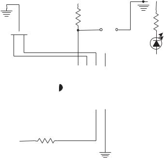
10.2.2 LED/Pushbutton Circuit
A slightly more complex circuit contains a pushbutton switch. In this case, the program monitors the state of the pushbutton and lights the LED accordingly. Figure 10-4 (in the following page) shows one possible wiring for the LED/pushbutton circuit.
If a switch reports a zero bit when active, it is described as active-low. A switch that reports a one-bit when pressed is said to be active-high. The pushbutton switch on the preceding figure is active-low. In the same manner, an output device can be wired so that it is turned on with a logic 0 and off with logic 1 on the port pin. A device turned on by the port current is said to be a source current device. When the device is turned on when the port reports logic 0 the line is said to sink the current. PICs and other CMOS devices operate better sinking than sourcing current. Table 10.2 shows the maximum sink and source currents for the 16F84 ports.
200 |
|
|
|
|
|
|
|
|
|
|
|
|
|
|
|
|
|
|
|
|
|
|
|
|
|
|
|
|
Chapter 10 |
|
|
|
|
|
|
|
+5 V |
|
|
|
|
|
|
|
|
|
|
|
|
|
|
|
|
|
|
|
|||
4 MHz |
|
|
|
R=4.7K Ohm |
|
|
|
|
|
|
|
|
|
|
|
|
|
|
|
|
|
|
|
|
R=330 Ohm |
||||
|
|
|
|
|
|
|
|
|
|
|
|
|
|
|
|
|
|
|
|
|
|
|
|||||||
|
|
|
|
|
|
|
|
|
|
|
|
|
|
|
|
|
|
|
|
|
|
|
|||||||
|
|
|
|
|
|
|
|
|
|
|
|
|
|
|
|
|
|
|
|
|
|
|
|
|
|
|
|
||
|
|
|
|
|
|
|
|
|
|
|
|
|
|
|
|
|
|
|
|
|
|
|
|
|
|
|
|
|
|
Osc |
|
|
|
|
|
|
|
|
|
|
|
|
|
|
|
|
|
|
|
|
|
|
|
|
LED |
||||
|
|
|
|
|
|
|
|
|
|
|
|
|
|
|
|
|
|
|
|
|
|
|
|
||||||
|
|
|
|
|
|
|
|
|
|
|
|
|
|
|
|
|
|
|
|
|
|
|
|
|
|||||
|
|
|
|
|
|
|
|
|
|
|
|
|
|
|
|
|
|
|
|
|
|
|
|
|
|||||
|
|
|
|
|
|
|
|
|
|
|
|
|
|
+5 V |
|
|
|
|
|
|
|
|
|
|
|
|
|
||
|
|
|
18 |
|
17 |
|
16 |
|
15 |
|
|
14 |
|
13 |
|
|
12 |
|
11 |
|
10 |
|
|
|
|
||||
|
|
|
|
|
|
|
|
|
|
|
|
|
|
|
|
|
|||||||||||||
|
|
|
|
|
|
|
|
|
|
|
|
|
|
|
|
|
|||||||||||||
|
|
|
|
|
|
|
|
|
|
|
|
|
|
|
|
|
|
|
|
|
|
|
|
|
|
|
|||
|
|
|
|
|
|
|
|
|
|
|
|
|
|
|
|
|
|
|
|
|
|
|
|
|
|
|
|||
|
|
|
|
|
RA1 |
RA0 |
OSC1 OSC2 |
Vdd |
RB7 |
|
RB6 |
RB5 |
RB4 |
|
|
||||||||||||||
|
|
|
|
|
|
|
|
|
|
|
|
16F84 |
|
|
|
|
|
|
|
|
|
|
|||||||
|
|
|
|
|
RA2 |
RA3 |
T0Tkl |
MCLR Vss |
RB0/INT RB1 |
RB2 |
RB3 |
|
|
||||||||||||||||
|
|
|
|
|
|
|
|
|
|
|
|
|
|
|
|
|
|
|
|
|
|
|
|
|
|
|
|
|
|
|
+5 V |
1 |
|
2 |
|
3 |
|
4 |
|
|
5 |
|
|
6 |
|
|
7 |
|
8 |
|
9 |
|
|
|
|
||||
|
|
|
|
|
|
|
|
|
|
|
|
|
|
|
|
|
|
|
|
|
|
|
|
|
|
|
|
||
|
|
|
|
|
|
|
|
|
|
|
|
|
|
|
|
|
|
|
|
|
|
|
|
|
|
|
|
||
|
|
|
|
10K Ohms |
|
|
|
|
|
|
|
|
|
|
|
|
|
|
|
|
|
|
|
|
|
|
|
||
Figure 10-4 LED/pushbutton Experimental Circuit |
|
|
|
|
|
|
|
|
|
|
|||||||||||||||||||
|
|
|
|
|
|
|
Table 10.2 |
|
|
|
|
|
|
|
|
|
|
|
|
|
|||||||||
|
|
|
Sink and Source Current for 16F84 Ports |
||||||||||||||||||||||||||
|
|
|
|
|
|
|
|
|
|
|
|
|
|
|
|
|
|
|
|
|
|
|
|
|
|
|
|
|
|
SOURCE |
|
ANY I/O PIN |
|
|
|
|
|
|
|
|
|
PORT A |
|
|
|
|
|
PORT-B |
|||||||||||
|
|
|
|
|
|
|
|
|
|
|
|
|
|
|
|
|
|
|
|
|
|
|
|
|
|
|
|
|
|
sink current |
|
25 mA |
|
|
|
|
|
|
|
|
|
80 mA |
|
|
|
|
|
150 mA |
|||||||||||
source current |
|
20 mA |
|
|
|
|
|
|
|
|
|
50 mA |
|
|
|
|
|
100 mA |
|||||||||||
The 4.7K Ohm resistor in the circuit of Figure 10-4 keeps RA0 high until the switch is pressed. This switch action determines that RA0 reads binary one when the switch is released and binary zero (low) when the switch is pressed (active).
To test if the switch in the circuit of Figure 10-4 is closed, the application can read RA0. If the value in the port is 1, then the switch is open (released). If 0, then the switch is closed. The following program, named LEDandPb, exercises the circuit in Figure 10-4:
;File: LEDandPb.asm
;Date: June 2, 2006
;Author: Julio Sanchez
;Processor: 16F84A
;Description:
;Circuit with LED wired to RB0 and pushbutton switch,
;active low, wired to RA0. Pushbutton action turns LED
;OFF when pressed and ON when released.
Programming Essentials: Input and Output |
201 |
;===========================
;switches ;===========================
;Switches used in __config directive:
; |
|
_CP_ON |
Code protection ON/OFF |
; * |
_CP_OFF |
|
|
; |
* |
_PWRTE_ON |
Power-up timer ON/OFF |
;_PWRTE_OFF
; |
_WDT_ON |
Watchdog timer ON/OFF |
|
|
; * _WDT_OFF |
|
|
|
|
; |
_LP_OSC |
Low power crystal |
occilator |
|
; * _XT_OSC |
External parallel |
resonator/crystal oscillator |
||
; |
_HS_OSC |
High speed crystal resonator (8 to |
10 MHz) |
|
; |
|
Resonator: Murate |
Erie CSA8.00MG = |
8 MHz |
; |
_RC_OSC |
Resistor/capacitor oscillator (simplest, 20% |
||
error)
;|
;|_____ * indicates setup values
|
processor |
16f84A |
|
include |
<p16f84A.inc> |
|
__config |
_XT_OSC & _WDT_OFF & _PWRTE_ON & _CP_OFF |
;===================================================== |
||
; |
variables in PIC RAM |
|
;===================================================== ; Not used in this program
;========================================================
; m a i n p r o g r a m
;========================================================
org |
0 |
; start at address 0 |
goto |
main |
|
;=============================
;space for interrupt handler ;=============================
org 0x04 ;=============================
;main program ;============================= main:
;Initialize all lines in Port-B for output
movlw |
B’00000000’ |
; w |
= |
00000000 |
binary |
||
tris |
PORTB |
; Set |
up |
Port-B for output |
|||
; Initialize Port-A, line 0, for input |
|
|
|
||||
movlw |
B’00000001’ |
; |
w |
= |
00000001 |
binary |
|
tris |
PORTA |
; |
Set |
up |
RA0 for input |
||
; Program loop to test state of pushbutton switch ;==============================
202 |
Chapter 10 |
;read PB switch state ;============================== LEDctrl:
;Push button switch on demo board is wired to Port-A bit 0
;Switch logic is active low
btfss |
PORTA,0 |
; Test. Skip |
next line |
if |
|
|
|
; |
bit is set |
|
|
goto |
turnOFF |
; |
Turn LED off routine |
|
|
;At this point Port-A bit 0 is not set
;Switch is pressed (active low action)
;Turn ON line 0 in Port-B
bsf |
PORTB,0 |
; RB0 high |
goto |
LEDctrl |
|
turnOFF: |
|
|
; Routine to turn OFF LED |
|
|
bcf |
PORTB,0 |
; RB0 low |
goto |
LEDctrl |
|
End
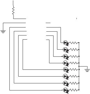
10.2.3 Multiple LED Circuit
The following circuit allows a few more programming complications since it contains a battery of eight LEDs, all wired to Port-B.
+5v
1 |
|
16F84 |
18 |
|
|
|
|
|
|||
|
2 |
|
RA2 |
RA1 |
|
|
Osc |
|
|||
|
|
|
|
17 |
|
|
|||||
|
|
|
|
|
|
|
|
|
|||
R=10K |
|
|
RA3 |
RA0 |
|
|
|
|
|
|
|
|
3 |
|
RA4/TOCKI |
OSC1 |
16 |
|
|
|
|
|
|
|
|
|
|
|
|
||||||
|
|
|
|
|
|
||||||
4 |
|
|
|
|
15 |
|
|
|
|
|
|
|
5 |
|
MCLR |
OSC2 |
|
|
|
|
|
|
|
|
Vss |
Vdd |
|
14 |
+5v |
|
|
|
|
||
|
|
|
|
|
|
||||||
|
|
|
|
|
|
||||||
|
6 |
|
|
|
|
|
|
|
|||
|
|
|
|
13 |
|
|
|
|
|
||
|
|
|
RB0/INT |
RB7 |
|
|
|
|
|
|
|
7 |
|
|
|
|
12 |
|
|
|
|
|
|
|
|
|
RB1 |
RB6 |
|
|
|
|
|
|
|
8 |
|
|
|
|
11 |
|
|
|
|
|
|
|
|
|
RB2 |
RB5 |
|
|
|
|
|
|
|
9 |
|
|
|
|
10 |
|
|
|
|
|
|
|
|
|
RB3 |
RB4 |
|
|
|
|
|
|
|
|
|
|
|
|
|
|
|
|
|
|
|
R=330x8 Ohm
Figure 10-5 Multiple LED Circuit
Programming Essentials: Input and Output |
203 |
The circuit in Figure 10-5 can be programmed to do different functions. For example, the eight LEDs can be visualized as representing an 8-bit binary number and the circuit can be programmed to count in binary from 0 to 255. Since the eight LEDs are all wired to Port-B, the binary count can be directly echoed on the port. The following program, named LEDCount, performs this operation:
;File: LEDCount.asm
;Date: June 3, 2006
;Author: Julio Sanchez
;Processor: 16F84A
;Description:
;Circuit with eight LEDs wired to RB0 to RB7.
;Program displays a binary count from 0 to 255 on
;LEDs.
;===========================
;switches ;===========================
;Switches used in __config directive:
; |
|
_CP_ON |
Code protection ON/OFF |
; * |
_CP_OFF |
|
|
; |
* |
_PWRTE_ON |
Power-up timer ON/OFF |
;_PWRTE_OFF
; |
_WDT_ON |
Watchdog timer ON/OFF |
|
|
; * _WDT_OFF |
|
|
|
|
; |
_LP_OSC |
Low power crystal |
occilator |
|
; * _XT_OSC |
External parallel |
resonator/crystal oscillator |
||
; |
_HS_OSC |
High speed crystal resonator (8 to |
10 MHz) |
|
; |
|
Resonator: Murate |
Erie CSA8.00MG = |
8 MHz |
; |
_RC_OSC |
Resistor/capacitor oscillator |
|
|
;|
;|_____ * indicates setup values processor 16f84A
include <p16f84A.inc>
__config _XT_OSC & _WDT_OFF & _PWRTE_ON & _CP_OFF
;=====================================================
; variables in PIC RAM
;===================================================== ; Declare variables at 2 memory locations
j |
equ |
0x0c |
k |
equ |
0x0d |
;========================================================
; m a i n p r o g r a m
;========================================================
org |
0 |
; start at address 0 |
goto |
main |
|
;============================= ; space for interrupt handler ;=============================