

134 |
Chapter 7 |
|
|
|
|
|
|
|
|
|
+9-12v |
|
|
Gnd |
|
|
|
|
|
|
|
|
|
|
|
|
|||
|
|
|
|
|
|
|
|
|
|
|
|
|
|
|
|
|
|
|
|
|
|
|
C2 |
C1 |
|||
|
|
|
|
|
|
|
|
|
|
|
|||
|
|
|
|
|
|
|
|
R9 |
|
|
|
|
|
|
|
|
|
|
|
|
|
|
|
|
|
|
1 |
|
|
|
|
|
|
|
|
|
|
|
|
|
6 |
|
|
|
|
|
|
|
|
|
|
|
|
|
F |
|
|
|
|
|
|
|
|
|
|
|
|
|
8 |
|
|
|
|
|
|
|
|
|
|
|
|
|
4 |
|
|
|
|
|
|
|
|
|
|
|
|
|
|
|
|
|
|
|
|
|
|
|
|
|
|
|
|
O1
Led Flasher 1.0
R1 L1
R2
L2
R3 L3
R4 L4
R5
L5
R6
L6
R7
L7
R8 L8
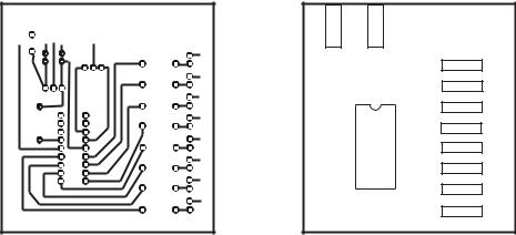
Figure 7-4 Drawing for Etching a PCB Board
The PCB in Figure 7-4 is intended for a copper-plated single-sided blank. The left-side image shows the actual circuit that is etched on the copper side of the board. The text and diagrams on the right-hand image are engraved (usually by silk screening) on the back side of the board and serve as a guide for welding the components. Refer to Appendix B for details on designing and building PCBs at the amateur level.
Several firms on the Internet offer PCB prototyping services from the circuit diagrams. In some cases the advertised turnaround time is a couple of days. One of these companies furnishes software tools for drawing the PCB in a format that they can use directly in manufacturing the prototypes. Googling “PCB prototypes” produces many hits.
7.1 PIC Architecture
PIC controllers are roughly classified by Microchip into three groups: baseline, mid-range, and high-performance. Within each of the groups the PICs are classified based on the first two digits of the PIC’s family type. However, the subclassification is not very strict, since there is some overlap. For this reason we find PICs with 16X designations that belong to the baseline family and others that belong to the mid-range group. In the following subsections we describe the basic characteristics of the various subgroups of the three major PIC families with 8-bit architectures.
7.1.1 Baseline PIC Family
This group includes members of the PIC10, PIC12, and PIC16 families. The devices in the Baseline group have 12-bit program words and are supplied in 6- to 28-pin packages. The microcontrollers in the baseline group are described as being suited for bat- tery-operated applications since they have low power requirements. The typical member of the Baseline group has a low pin count, flash program memory, and low power requirements. The following types are in the Baseline group.

The Microchip PIC |
135 |
PIC10 Devices
The PIC10 devices are low-cost, 8-bit, flash-based CMOS microcontrollers. They use 33 single-word, single-cycle instructions (except for program branches, which take two cycles). The instructions are 12-bits wide. The PIC10 devices feature power-on reset, an internal oscillator mode that saves having to use ports for an external oscillator. They have a power-saving SLEEP mode, a Watchdog Timer, and optional code protection.
The recommended applications of the PIC10 family range from personal care appliances and security systems to low-power remote transmitters and receivers. The PICs of this family have a small footprint and are manufactured in formats suitable for both through-hole and surface mount technologies. Table 7.1 summarizes the characteristics of PIC10 devices.
Table 7.1
PIC10F Devices
|
10F200 |
10F202 |
10F204 |
10F206 |
|
|
|
|
|
Clock: |
|
|
|
|
Maximum Frequency |
|
|
|
|
of Operation (MHz) |
4 |
4 |
4 |
4 |
Memory: |
|
|
|
|
Flash Program |
|
|
|
|
Memory |
256 |
512 |
256 |
512 |
Data Memory (bytes) |
16 |
24 |
16 |
24 |
Peripherals: |
|
|
|
|
Timer Module(s) |
TMR0 |
TMR0 |
TMR0 |
TMR0 |
Wake-up from Sleep |
Yes |
Yes |
Yes |
Yes |
Comparators |
0 |
0 |
1 |
1 |
Features: |
|
|
|
|
I/O Pins |
3 |
3 |
3 |
3 |
Input Only Pins |
1 |
1 |
1 |
1 |
Internal Pull-ups |
Yes |
Yes |
Yes |
Yes |
In-Circuit Serial |
|
|
|
|
Programming |
Yes |
Yes |
Yes |
Yes |
Instructions |
33 |
33 |
33 |
33 |
Packages: |
|
|
|
|
6-pin SOT-23
8-pin PDIP
Two other PICs of this series are the 10F220 and the 10F222. These versions include four I/O pins and two analog-to-digital converter channels. Program memory is 256 words on the 10F220 and 512 in the 10F222. Data memory is 16 bytes on the F220 and 23 in the F222.
PIC12 Devices
The PIC12C5XX family are 8-bit, fully static, EEPROM/EPROM/ROM-based CMOS microcontrollers. They use RISC architecture and have 33 single-word, single-cycle instructions (except for program branches, which take two cycles). Like the PIC10 family, the PIC12C5XX chips have power-on reset, device reset, and internal timer. Four oscillator options can be selected, including a port-saving internal oscillator and

136 |
Chapter 7 |
a low-power oscillator. These devices can operate in SLEEP mode and have Watchdog Timer and code-protection features.
Table 7.2
PIC 12Cxxx and 12CExxx Devices
|
|
12C508(A) |
12C518 |
12CE519 |
12C671 |
12CE674 |
|
|
12C509A |
|
|
12C672 |
|
|
|
12CR509A |
|
|
|
|
|
|
|
|
|
|
|
Clock: |
|
|
|
|
|
|
|
Maximum |
|
|
|
|
|
|
Frequency |
|
|
|
|
|
|
of Operation |
|
|
|
|
|
|
(MHz) |
4 |
4 |
4 |
10 |
10 |
Memory: |
|
|
|
|
|
|
|
EPROM |
|
|
|
|
|
|
Program |
|
|
|
|
|
|
Memory |
512/1024/1024 |
512x12 |
1024x12 |
1024/2048/ |
2048x14 |
|
|
x12 |
|
|
1024x12 |
|
|
RAM Data |
|
|
|
|
|
|
Memory |
|
|
|
|
|
|
(bytes) |
25/41/41 |
25 |
41 |
128 |
128 |
Peripherals: |
|
|
|
|
|
|
|
EEPROM |
|
|
|
|
|
|
Data Memory |
|
|
|
|
|
|
(bytes) |
— |
16 |
16 |
0/0/16 |
16 |
|
Timer |
|
|
|
|
|
|
Module(s) |
TMR0 |
TMR0 |
TMR0 |
TMR0 |
TMR0 |
|
A/D Converter |
|
|
|
|
|
|
(8-bit) |
|
|
|
|
|
|
Channels |
— |
— |
— |
4 |
4 |
Features: |
|
|
|
|
|
|
|
Wake-up |
|
|
|
|
|
|
from SLEEP |
|
|
|
|
|
|
on pin |
|
|
|
|
|
|
change |
Yes |
Yes |
Yes |
Yes |
Yes |
|
Interrupt |
|
|
|
|
|
|
Sources |
— |
— |
— |
4 |
4 |
|
I/O Pins |
5 |
5 |
5 |
5 |
5 |
|
Input Pins |
1 |
1 |
1 |
1 |
1 |
|
Internal |
|
|
|
|
|
|
Pull-ups |
Yes/Yes/No |
Yes |
Yes |
Yes |
Yes |
|
In-Circuit |
|
|
|
|
|
|
Serial |
|
|
|
|
|
|
Programming |
Yes/No |
Yes |
Yes |
Yes |
Yes |
|
Number of |
|
|
|
|
|
|
Instructions |
33 |
33 |
33 |
35 |
35 |
|
Packages |
8-pin DIP |
8-pin DIP |
8-pin DIP |
8-pin DIP |
8-pin DIP |
|
|
SOIC |
JW,SOIC |
JW. SOIC |
SOIC |
JW |
The PIC12C5XX devices are recommended for applications including personal care appliances, security systems, and low-power remote transmitters and receivers. The internal EEPROM memory makes possible the storage of user-defined codes and passwords as well as appliance setting and receiver frequencies. The various packages allow through-hole or surface mounting technologies. Table 7.2 lists the characteristics of some selected members of this PIC family.
Two other members of the PIC12 family are the 12F510 and the 16F506. In most respects these devices are similar to the other members of the PIC12 family previously described, except that the 12F510 and 16F506 both have flash program memory. Table 7.3 lists the most important features of these two PICs.

The Microchip PIC |
|
137 |
|
Table 7.3 |
|
|
|
PIC12F510 and 12F506 |
|
|
|
|
|
|
|
|
16F506 |
12F510 |
|
Clock: |
|
|
|
Maximum Frequency of Operation (MHz) |
20 |
8 |
|
Memory: |
|
|
|
Flash Program Memory |
1024 |
1024 |
|
Data Memory (bytes) |
67 |
38 |
|
Peripherals: |
|
|
|
Timer Module(s) |
TMR0 |
TMR0 |
|
Wake-up from Sleep on Pin Change |
Yes |
Yes |
|
Features: |
|
|
|
I/O Pins |
11 |
5 |
|
Input Only Pin |
1 |
1 |
|
Internal Pull-ups |
Yes |
Yes |
|
In-Circuit Serial Programming |
Yes |
Yes |
|
Number of Instructions |
33 |
33 |
|
Packages |
14-pin PDIP, |
8-pin PDIP |
|
|
SOIC, |
SOIC, |
|
|
TSSOP |
MSOP |
|
|
|
|
|
Two other members of the PIC12F are the 12F629 and 12F675. The only difference between these two devices is that the 12F675 has a 10-bit analog-to-digital converter while the 629 has no A/D converter. Table 7.4 lists some important features of both PICs.
Table 7.4
PIC12F629 and 12F675
|
12F629 |
12F675 |
Clock: |
|
|
Maximum Frequency of Operation (MHz) |
20 |
20 |
Memory: |
|
|
Flash Program Memory |
1024 |
1024 |
Data Memory (SRAM bytes) |
64 |
64 |
Peripherals: |
|
|
Timers 8/16 bits |
1/1 |
1/1 |
Wake-up from Sleep on Pin Change |
Yes |
Yes |
Features: |
|
|
I/O Pins |
6 |
6 |
Analog comparator module |
Yes |
Yes |
Analog-to-digital converter |
No |
10-bit |
In-Circuit Serial Programming |
Yes |
Yes |
Enhanced Timer1 module |
Yes |
Yes |
Interrupt capability |
Yes |
Yes |
Number of Instructions |
35 |
35 |
Relative addressing |
Yes |
Yes |
Packages |
8-pin PDIP, |
8-pin PDIP |
|
SOIC, |
SOIC, |
|
DFN-S |
DFN-S |
|
|
|

138 |
Chapter 7 |
Several members of the PIC12 family; the 12F635, 12F636, 12F639, and 12F683, are equipped with special power-management features (called nano-watt technology). These devices were especially designed for systems that require extended battery life.
PIC14 Devices
The single member of this family is the PIC14000. The 14000 is built with CMOS technology; this makes it fully static and gives the PIC an industrial temperature range. The 14000 is recommended for battery chargers, power supply controllers, power management system controllers, HVAC controllers, and for sensing and data acquisition applications. Table 7.5 lists the most important characteristics of this PIC.
Table 7.5
PIC14000
Clock: |
|
|
Maximum Frequency of Operation (MHz) |
20 |
|
Memory: |
|
|
Flash Program Memory |
4096 |
|
Data Memory (SRAM bytes) |
192 |
|
Peripherals: |
|
|
Timers (16 bits with capture) |
1 |
|
Wake-up from Sleep on Pin Change |
Yes |
|
Features: |
|
|
I/O Pins |
22 |
|
Analog-to-digital converter |
2 |
channels |
On-chip temperature sensor |
1 |
|
On-chip comparator modules |
2 |
|
In-Circuit Serial Programming |
Yes |
|
Interrupt capability: |
|
|
Internal |
6 |
sources |
External |
5 |
sources |
I2C-compatible serial port |
1 |
|
Number of Instructions |
35 |
|
Relative addressing |
Yes |
|
Packages |
22-pin PDIP, |
|
|
SOIC, SSOP, |
|
|
Windowed CERDIOP |
|
|
|
|
7.1.2 Mid-range PIC Family
The mid-range PIC family includes members of the PIC12 and PIC16 groups. According to Microchip, the mid-range PICs all have 14-bit program words with either flash or OTP program memory. Those with flash program memory have EEPROM data memory and support interrupts. Some members of the mid-range group have USB, I2C, LCD, USART, and A/D converters. Implementations range from 8 to 64 pins. In the following subsections the basic characteristics of some mid-range PICs are listed.

The Microchip PIC |
139 |
PIC16 Devices
This is by far the most extensive PIC family. Currently, over 80 versions of the PIC16 are listed in production by Microchip. The remainder of this book is devoted to programming two of these PICs: the 16F84 and the 16F877. Here we listed a few of the most prominent members of the PIC16 family and their most important features. The Microchip website has more detailed information on these devices.
Table 7.6
PIC16 Devices
|
16C432 |
16C58 |
16C770 |
16F54 |
16F84A |
16F946 |
|
Clock: |
|
|
|
|
|
|
|
Maximum Frequency MHz |
20 |
40 |
|
20 |
20 |
20 |
20 |
Memory: |
|
|
|
|
|
|
|
Program memory type |
OTP |
OTP |
OTP |
Flash |
Flash |
Flash |
|
K-bytes |
3.5 |
3 |
|
3.5 |
0.75 |
1.75 |
14 |
K-words |
2 |
2 |
|
2 |
0.5 |
1 |
8 |
Data EEPROM |
0 |
0 |
|
0 |
0 |
64 |
256 |
Peripherals: |
|
|
|
|
|
|
|
I/O channels |
12 |
12 |
|
16 |
12 |
13 |
53 |
ADC channels |
0 |
0 |
|
6 |
0 |
0 |
8 |
Comparators |
0 |
0 |
|
0 |
0 |
0 |
2 |
Timers |
1/8-bit |
1/8-bit |
2/8-bit |
1/8-bit |
1/8-bit |
2/8-bit |
|
|
|
1/16-bit |
|
|
|
1/16-bit |
|
Watchdog timer |
Yes |
Yes |
Yes |
Yes |
Yes |
Yes |
|
Features: |
|
|
|
|
|
|
|
ICSP |
Yes |
No |
|
Yes |
No |
Yes |
Yes |
ICD |
No |
No |
|
No |
No |
0 |
1 |
Pin count |
20 |
18 |
|
20 |
18 |
18 |
64 |
Communications |
- |
- |
|
MPC/SPI |
- |
- |
AUSART |
Packages |
20/CERDIP, 18/CERDIP |
20/CERDIP |
18/PDIP |
18/PDIp |
64/TQFP |
||
|
20/SSOP |
18/PDIP |
20/PDIP |
18/SOIC |
18/SOIC |
|
|
|
208mil |
18/SOIC |
20/SOIC |
300mil |
300mil |
|
|
|
300mil |
300mil |
|
|
|
|
|
|
|
|
|
|
|
|
|
7.1.3 High-Performance PIC Family
The high-performance PICs belong to the PIC18 group. They have 16-bit program words, flash program memory, a linear memory space of up to two Mbytes, and proto- col-based communications facilities. They all support internal and external interrupts and have a much larger instruction set than members of the baseline and mid-range families.
PIC18 Devices
The PIC18 family is also a large one, with over 70 different variations currently in production. The PIC18 family uses 16-bit program words and are furnished in 18 to 80 pin packages. Microchip describes the PICs in this family as high-performance with integrated A/D converters. They have 32-level stacks and support interrupts. The instruction set is much larger and starts at 79 instructions. The PICs in this family have flash program memory, a linear memory space of up to 2 Mbytes, 8-by-8 bit hardware multiplier, and communications peripherals and protocols. Table 7.7 lists some members of the PIC18 family.

140 |
|
|
|
|
Chapter 7 |
|
|
|
|
Table 7.7 |
|
|
|
|
|
|
PIC18 Devices |
|
|
|
|
|
|
|
|
|
|
|
|
18F222 |
18F2455 |
18F2580 |
18F4580 |
18F8622 |
Clock: |
|
|
|
|
|
|
Maximum Frequency MHz |
40 |
48 |
40 |
40 |
40 |
|
Memory: |
|
|
|
|
|
|
|
Program memory type |
flash |
flash |
flash |
flash |
flash |
|
K-bytes |
4 |
24 |
32 |
32 |
64 |
|
K-words |
2 |
12 |
16 |
16 |
321 |
|
Data EEPROM |
256 |
256 |
256 |
256 |
1024 |
Peripherals: |
|
|
|
|
|
|
|
I/O channels |
25 |
23 |
25 |
36 |
70 |
|
ADC channels |
10 |
10 |
8 |
11 |
16 |
|
Comparators |
2 |
2 |
0 |
2 |
2 |
|
Timers |
1/8-bit |
1/8-bit |
1/8-bit |
1/8-bit |
2/8-bit |
|
|
3/16-bit |
3/16-bit |
3/16-bit |
3/16-bit |
3/16-bit |
|
Watchdog timer |
Yes |
Yes |
Yes |
Yes |
Yes |
Features: |
|
|
|
|
|
|
|
EUSART |
Yes |
Yes |
Yes |
Yes |
2 |
|
ICSP |
Yes |
Yes |
Yes |
Yes |
Yes |
|
ICD |
1 |
3 |
3 |
3 |
3 |
|
Pin count |
28 |
28 |
28 |
44 |
80 |
|
Communications |
MPC/SPI |
MPC/SPI/USB |
MPC/SPI |
MPC/SPI |
2-MPC/SPI |
|
Packages |
28/PDIP, |
28/SOIC |
28/QFN |
40/PDIP |
80/TQFP |
|
|
28/SOIC |
28/PDIP |
20/PDIP |
44/QFN |
|
300mil 300mil 300mil 44/TQFP