

Digital Logic, Arithmetic, and Conversions |
67 |
A third approach is based on the manipulations performed during longhand multiplication. For example, the multiplication of 00101101B (45 decimal) by 01101101B (109 decimal) can be expressed as a series of products and shifts, in the following manner:
|
|
|
|
|
|
|
0 0 1 0 |
1 |
1 |
0 |
1 |
B = 45 decimal |
|||
|
times |
|
|
|
0 1 1 0 |
1 |
1 |
0 |
1 |
B = 109 decimal |
|||||
|
|
|
|
|
|
|
----------------- |
||||||||
|
|
|
|
|
|
|
0 |
0 |
1 |
0 |
1 |
1 |
0 |
1 |
|
|
|
|
|
|
|
0 |
0 |
0 |
0 |
0 |
0 |
0 |
0 |
|
|
|
|
|
|
|
0 |
0 |
1 |
0 |
1 |
1 |
0 |
1 |
|
|
|
|
|
|
|
0 |
0 |
1 |
0 |
1 |
1 |
0 |
1 |
|
|
|
|
|
|
|
0 |
0 |
0 |
0 |
0 |
0 |
0 |
0 |
|
|
|
|
|
|
|
0 |
0 |
1 |
0 |
1 |
1 |
0 |
1 |
|
|
|
|
|
|
|
0 |
0 |
1 |
0 |
1 |
1 |
0 |
1 |
|
|
|
|
|
|
|
0 |
0 |
0 |
0 |
0 |
0 |
0 |
0 |
|
|
|
|
|
|
|
|
------------------------------- |
|
||||||||||||||
0 0 1 0 0 1 1 0 0 1 0 1 |
0 |
0 |
1 |
B = 4905 decimal |
|||||||||||
The actual calculations in this method of binary multiplication are quite simple since the product by a 0 digit is zero and the product by a 1 digit is the multiplicand itself. Consequently, the multiplication routine simply tests each digit in the multiplier. If the digit is zero no action need be performed; if the digit is one, the multiplicand is shifted left and added into an accumulator.
The storage allocation to hold the product of a multiplication operation is not the same as that to hold the sum. In multi-byte addition one additional byte is required to hold the sum. In multiplication the storage allocation must be twice the size of the operands. For example, byte multiplication requires a two-byte storage, while multiplying two double-byte operands requires a four-byte storage allocation.
4.4.3 Unsigned Division
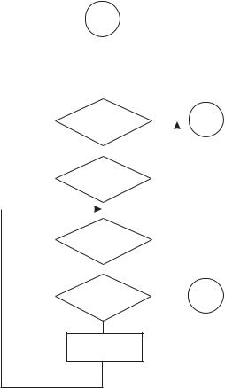
If multiplication can be reduced to repeated addition, then division can be conceptualized as repeated subtraction. In the case of division, the quotient (result) is the number of times the divisor must be subtracted from the dividend before zero or a negative value results from the subtraction. The flowchart in Figure 4-6 (in the following page) shows the logic steps in unsigned division.
In Figure 4-6 note that the logic tests for a zero divisor, since division by zero is mathematically undefined. Also, since the operation is unsigned, the result cannot be negative; therefore, the divisor must be larger than the dividend. Finally, the logic must consider the case in which subtracting the divisor from the reminder produces a negative value, in which case an adjustment is necessary to produce a valid quotient. This adjustment avoids the need for searching for a trial divisor, as in the case in the common longhand division algorithm. In machine code the negative result is detected as an overflow (carry flag set) from the subtraction.
4.5 Signed Binary Arithmetic
In two’s complement and sign-magnitude representations the high-order bit represents the sign of the operand, while its magnitude is represented in the remaining bits. Therefore, in the case of signed numbers, a carry out of the high-order bit is meaning-
68 |
Chapter 4 |
|
START |
|
|
|
|
|
|
|
|||
|
|
|
|
|
|
|
|
|
|
|
|
|
|
|
|
|
|
|
|
|
|
|
|
|
A = DIVIDEND |
|
|
|
|
|
|
|
|||
|
B = DIVISOR |
|
|
|
|
|
|
|
|||
|
PERFORM Q = A / B |
|
|
|
|
|
|
|
|||
|
Q (QUOTIENT) = 0 |
|
|
|
|
|
|
|
|||
|
R (REMAINDER) = A |
|
|
|
|
|
|
|
|||
|
|
|
|
|
YES |
|
|
|
|
|
|
|
|
|
|
|
|
|
|
|
|
||
|
DIVISOR = 0 |
|
|
|
|
|
ERROR |
||||
|
|
|
|
|
|
||||||
|
? |
|
|
|
|
|
|
|
|
||
|
|
|
|
|
|
|
|
|
|||
|
|
|
|
|
YES |
|
|
|
|
|
|
|
|
|
|
|
|
|
|
|
|
||
|
DIVIDEND < |
|
|
|
|
|
|
||||
|
|
|
|
|
|
|
|
||||
|
DIVISOR |
|
|
|
|
|
|
|
|||
|
? |
|
|
|
|
|
|
|
|
||
|
|
|
NO |
YES |
|
|
|
|
|
||
|
|
|
|
|
|
|
|
||||
|
|
|
|
|
|
|
|
||||
|
|
|
|
|
|
|
|
|
|
||
|
|
|
|
|
|
Q = Q - 1 |
|||||
|
REMINDER < 0 |
|
|
|
|||||||
|
|
|
|
R = R + B |
|||||||
|
? |
|
|
|
|
||||||
|
|
|
|
|
|
|
|
|
|||
|
|
|
NO |
YES |
|
|
|
|
|
||
|
|
|
|
|
|
|
|
||||
|
|
|
|
|
|
|
|
|
|
||
|
REMINDER = 0 |
|
|
|
|
|
DONE |
||||
|
|
|
|
|
|||||||
|
? |
|
|
|
|
|
|
|
|
||
NO
R = R - B
Q = Q + 1
Figure 4-6 Unsigned Division Flowchart
less since the high-order bit is not a magnitude bit. For example, consider the following operation in an 8-bit device that performs unsigned and two’s complement addition:
80 = 0101 0000B
+90 = 0101 1010B
------------------
170 = 1010 1010B
If the operands are assumed to be in unsigned binary format the result is valid. However, if the operands (the decimal values 80 and 90) are assumed to be positive numbers in two’s complement form, then the result is invalid since the positive number 170 cannot be represented in an 8-bit two’s complement encoding.
Clearly, multi-byte operations on signed representations cannot be performed identically as with unsigned operands. Table 4.2 shows the unsigned and two’s complement representations of one-byte numbers.

Digital Logic, Arithmetic, and Conversions |
69 |
Table 4.2
Signed and Unsigned Representations of One-Byte Numbers
BINARY |
2’S COMPLEMENT |
UNSIGNED |
|
|
|
0000 0000 |
0 |
0 |
0000 0001 |
1 |
1 |
0000 0010 |
2 |
2 |
0000 0011 |
3 |
3 |
. |
. |
. |
. |
. |
. |
. |
. |
. |
0111 1111 |
127 |
127 |
1000 0000 |
-128 |
128 |
1000 0001 |
-127 |
129 |
1000 0010 |
-126 |
130 |
1000 0011 |
-125 |
131 |
. |
. |
. |
. |
. |
. |
1111 1110 |
-2 |
254 |
1111 1111 |
-1 |
255 |
4.5.1 Overflow Detection in Signed Arithmetic
In unsigned addition the carry flag is magnitude-related. It is set when there is a carry out of the high-order bit of the destination operand, which takes place when its capacity has been exceeded. This is usually described as an overflow condition. However, a carry out of the high-order bit of the result is not always meaningful in signed arithmetic. For example, suppose the following two’s complement addition:
|
Decimal |
binary |
|
|
127 |
0111 |
1111 |
+ |
127 |
0111 |
1111 |
|
---- |
--------- |
|
|
?? |
1111 |
1110 |
In this case the sum clearly exceeds the capacity of the format, since the largest positive value that can be represented in a two’s complement 8-bit format is 127 (see Table 4-2). However, the operation did not generate a carry out of the high-order bit. Therefore, the carry flag could not have been used to detect the overflow error in this case.
Now consider the addition of two negative numbers in two’s complement form:
|
Decimal |
binary |
|
|
-4 |
1111 |
1100 |
+ |
-5 |
1111 |
1011 |
|
---- |
--------- |
|
|
-9 |
C <= 1111 |
0111 |
In this case the addition operation generated a carry out of the high-order bit; however, the sum is arithmetically correct. In fact, any addition of negative operands in two’s complement notation generates a carry out of the most significant bit.

70 |
Chapter 4 |
These two examples show that the carry flag, by itself, cannot be used to detect an error or no-error condition in two’s complement arithmetic. Detecting an overflow condition in two’s complement representations requires observing the carry into the high-order bit of the encoding as well as the carry out. In both previous examples we note that there was a carry into the high-order bit of the result. However, in the first case there was no carry out. The general rule is: two’s complement overflow takes place when the carry into and the carry out of the high-order bit have opposite values. Figure 4-7 is a flowchart to detect overflow in signed arithmetic.
|
|
|
|
|
|
START |
|
|
|
|
|
|
|||
|
|
|
|
|
|
|
|
|
|
|
|
|
|
||
|
|
|
|
|
|
|
|
|
|
|
|
|
|
|
|
|
|
|
A = FIRST SIGNED ADDEND |
|
|
|
|||||||||
|
|
|
B = SECOND SIGNED ADDEND |
|
|
|
|||||||||
|
|
|
|
PERFORM C = A + B |
|
|
|
|
|
|
|||||
|
|
|
|
|
|
|
|
|
|
|
|
|
|
|
|
|
|
|
NO |
|
|
|
|
|
|
|
YES |
|
|
||
|
|
|
|
|
CARRY INTO |
|
|
|
|||||||
|
|
|
|
|
|
BIT 7 |
|
|
|
|
|
|
|||
|
|
|
|
? |
|
|
|
|
|
|
|
|
|||
|
|
|
YES |
NO |
|
|
|||||||||
CARRY OUT |
|
CARRY OUT |
|||||||||||||
|
|
|
|
OVERFLOW |
|
|
|
|
|
OF BIT 7 |
|||||
OF BIT 7 |
|
|
|
|
|
|
|
|
|
||||||
|
|
|
|
|
|
|
|
|
|
|
|
||||
|
|
|
|
|
|
|
|
|
|
|
|
|
|
||
? |
|
|
|
|
|
|
|
|
|
|
|
|
? |
||
|
|
|
|
|
|
|
|
|
|
|
|
|
|
||
|
NO |
|
|
|
|
|
|
|
|
|
|
|
|
YES |
|
|
|
|
|
|
|
|
|
|
|
|
|
|
|
||
|
|
|
|
|
|
|
|
|
|
|
|
|
|
|
|
|
|
|
|
|
|
NO |
|
|
|
|
|
|
|
||
|
|
|
|
|
|
OVERFLOW |
|
|
|
|
|
|
|||
Figure 4-7 Detecting Overflow in Two’s Complement Arithmetic
Most microprocessors and some high-end microcontrollers contain hardware facilities for detecting signed arithmetic overflow. In some cases the hardware support consists of a single overflow flag that is set whenever the result of an arithmetic operation exceeds the capacity of the format. In other cases, as in the PIC 18CXX2 family, the status register contains a negative bit flag that indicates a 1-bit in the sign bit position, as well as an overflow bit that is set whenever there is an overflow from the magnitude bits (0 to 6) into the sign bit (bit 7) of the destination operand. In this device, software can test one or both of these flags to detect two’s complement overflow.
In lowand mid-range devices, with no hardware support for signed arithmetic, detecting a two’s complement overflow is by no means simple. Without a hardware flag to report a carry condition into a particular bit position, software is confronted with several possible alternatives, but none is simple or straightforward.
4.5.2 Sign Extension Operations
Observing the carry into and the carry out of the most significant bit is a valid way of detecting overflow of a two’s complement arithmetic operation. In theory, the logic described in the flowchart of Figure 4-7 can be implemented in devices without hard-

Digital Logic, Arithmetic, and Conversions |
71 |
ware support for signed overflow; however, the processing is complicated and therefore costly in execution time. An alternative approach is to ensure that the format has sufficient capacity to store the arithmetic result. The rule developed previously lets us determine that, for addition and subtraction, the destination format must have at least one more byte than the operands. In multiplication, the destination operand must be at least twice the size of the source operands.
A simple mechanism for extending the capacity of two’s complement encoding is called sign extension. The process consists of copying the sign bit into the high-order bit positions of the extended encoding. For example, to extend a two’s complement 8-bit number into 16 bits, copy the sign bit of the original value (bit number 7) into all the bits of the extended byte. The process is shown in Figure 4-8 for both positive and negative operands.
Extended
bit
0 0 1 1 1 1 0 0
Sign extension of a positive number
0 |
0 |
0 |
0 |
0 |
0 |
0 |
0 |
|
0 |
0 |
1 |
1 |
1 |
1 |
0 |
0 |
|
|
|
|
|
|
|
|
|
|
|
|
|
|
|
|
|
Extended
bit
1 0 1 1 1 1 0 0
Sign extension of a negative number
1 |
1 |
1 |
1 |
1 |
1 |
1 |
1 |
|
1 |
0 |
1 |
1 |
1 |
1 |
0 |
0 |
|
|
|
|
|
|
|
|
|
|
|
|
|
|
|
|
|
Figure 4-8 Sign Extension of Two’s Complement Numbers
4.5.3 Multi-byte Signed Operations
Signed operations on two’s complement numbers encoded in multiple bytes can be performed using the processor’s arithmetic primitives. Consider the addition of the numbers -513 and -523, each one encoded in 16-bit two’s complement form:
decimal |
|
binary |
|
|
|
HOB |
|
LOB |
|
-513 |
1111 |
1101 |
1111 |
1111 |
-523 |
1111 |
1101 |
1111 |
0101 |
--------------------------
-1036 |
1111 1011 |
1111 0100 |
In the preceding example, adding the low-order bytes produces the sum shown, plus a carry. Adding the high-order bytes plus the carry, and discarding the overflow, produces the sum of high-order bytes shown above. The result is the correct value in two’s complement form. The fact that the result did not overflow the capacity of the 16-bit format can be ascertained by observing that there was a carry into the fif-