


Timer Operations 245
2.Do an analysis of a substantial piece of writing and create a Huffman code that will encode the data efficiently. It is recommended that the first three pages of a novel be used for this analysis. Compute the average number of bits per character that this code generates. Hint: you might want to write a program in C for the host com puter to calculate the histogram and help create the Huffman codes.
3.Write a program that will implement the above code so that an operator can type the data into a computer and the Huffman code sequences will be generated. You should break the message se quences into moderate size bit strings, 500 to 1000 bits, and restart.
4.Create a Huffman tree table as was used in Listing 5-1 to decode the Huffman code developed in Exercise 2.
5.How can you double the number of entries in a Huffman tree by adding only one bit to the code strings?
Timer Operations
The programs written in the earlier sections on sorting and data compression were more computer programs than microcontroller programs. The code written would work on a desktop system or a mainframe computer if needed. In this section, we graduate to true microcontroller programming. The set up of the MC68HC11 family requires that the programmer have a detailed knowledge of the operation of the device. Even though the program is written in a high-level language, it is the responsibility of the programmer to properly set all of the necessary control bits to make the device work as desired. Unfortunately, there are few helpful tools that can guide you through this portion of the program. You must first understand what you want the device to do and then dig through its specifications to find the necessary bits to be set to make it perform as desired. It is highly recommended that prior to an attempt at programming this device that you familiarize yourself with the technical data manual for it as well as the reference manual for the family that is found on the CD-ROM.
The timer subsystem in the MC68HC11 family contains both input capture operations and output compare functions. In this section, we will explore these subsystems associated with the MC68HC11Ex series. The main difference between the Ex series and the other devices lies in the number of output compare and input capture systems on
246 Chapter 5 Programming Large 8-Bit Systems
each device. The Ex series has four output compares, three input captures, and one timer that can be programmed as either output compare or input capture. The other devices have three input captures and five output compares.
Output Compare Subsystems
What does an output compare do? The explanation of the timer subsystem must always begin with the 16-bit timer counter called TCNT that is always counting at some fraction of the system bus frequency. The bus frequency is always one-fourth of the system crystal frequency. The prescaler frequency is set to the bus frequency divided by either 1, 4, 8, or 16 depending on the bits PR1 and PR0 in the register TMSK2. The timer counter register can be read at any time but it cannot be written to. The Output Compare 1 is special. All of the discussion that follows is valid for all output compares, but—as will be shown later— Output Compare 1 has capability beyond the others.
Associated with each output compare system there is a single 16-bit output compare register containing the time that the program needs an event to occur. When TCNT contents matches that of OCx, an OCx event occurs. Note that I say an event, not output. What happens when the contents of the TCNT matches the contents of OCx is up to the program. Associated with each output compare is a pin that can be set, reset, or toggled when an output compare occurs. When an output compare occurs, the corresponding OCxF flag bit is set in the TFLG1 register. This bit can be examined asynchronously by the program to determine whether an output compare has occurred. If the corresponding bit in the TMSK1 register is set when the OCxF flag bit is set, an interrupt will be requested by the part and the event will be processed asynchronously. These are the operations of all output compare subsystems in the part.
There are three input captures, four output compares, and one timer that can be programmed as either an output or an input. This timer is controlled by the I4O5 bit in the PACTL register. When this bit is a zero, the programmable timer is an output compare. Otherwise when the bit is set, the programmable timer is an input capture. Often it is desirable to have an output compare operation be initiated by the completion of another output compare. Output Compare 1 is set up in just this manner. The bits in the OC1M and the OC1D registers control the coupling between the Output Compare 1 and the other

Timer Operations 247
output compare subsystems. When one of the mask bits, say OC1M5, is set in the OC1M and a compare occurs on OC1, in addition to the normal operation that usually occurs when OC1 happens, the contents of the corresponding bit, OC1D5, in the OC1D register is sent to the output compare pin, which in this case is OC3. Completely independent of the operation of OC1, OC3 could be set to toggle at some time. Output Compare 3 could be programmed to be a PWM output where Output Compare 1 establishes the period of the output, and Output Compare 3 establishes the on time.
The applications for use of the coupled output compares are unlimited. An accurate PWM is but one of several. These outputs could be set up to establish an output sequence to drive a stepper motor. The control of acceleration or deceleration of the motor is easily controlled by merely selecting the base time used with OC1.
If you recall, the output compare-based PWM system discussed for the MC68HC05 had several limitations. For example, that system required that the system operate from interrupt service routines. The latency time of interrupt service was so long that the minimum pulse width was considerably longer than one would expect. Also, the interrupt service timing dictated the maximum on time for the pulse, which again was not nearly 100%. Let us look at how we would do a PWM system with the coupled output compare systems.
#include “hc11e9.h”
/* This program will provide a PWM output to OC3, or
PA5. The period will be the integer value found in period, and the on time will be the integer value found in time_on. Keep time_on less than period. */
#define PERIOD 0X1000 #define TIME_ON 0x0800
WORD period=PERIOD, time_on=TIME_ON;
main()
{
OC1M.OC1M7=ON; /* sent OC1 out to PA7 */

248 Chapter 5 Programming Large 8-Bit Systems
OC1M.OC1M5=ON; /* couple OC1 to OC3 */ OC1D.OC1D5=ON; /* turn on OC3 when OC1 occurs */ TCTL1.OL3=ON; /* toggle OC3 when OC3 occurs */ PACTL.DDRA7=ON; /* make OC1 an output to PA7 */ TOC1=TCNT+period; /* set OC1 to the period */ TOC3=TOC1+time_on; /* set OC3 to the time on */ FOREVER
{
if(TFLG1&OC1F)
{
TFLG1=OC1F; /* reset OC1 interrupt flag */ TOC1+=period;
OC1D.OC1D7 ^=ON; /* toggle the output Compare 1 bit */
}
if(TFLG1&OC3F)
{
TFLG1=OC3F;/*reset OC3 interrupt flag */ TOC3=TOC1+time_on;
}
}
}
Listing 5-4: Pulse Width Modulation Routine PWM.C
This routine starts with the inclusion of the header file hc11e9.h. It is created as a main program to demonstrate how it will work, but should be changed to a subroutine later. The period and time_on interval are declared as global variables. They are declared to be the type WORD. WORD is a typedef synonym for the type unsigned int . The main program begins with a series of five initialization instructions. The first two instructions
OC1M.OC1M7=ON;
OC1M.OC1M5=ON;
declare that the output of OC1 should be sent to the outside, which will be to pin PA7, and that whenever OC1 occurs, OC3 through pin PA5 should be activated.

Timer Operations 249
The instruction
OC1D.OC1D5=ON;
indicates that when OC1 occurs, OC3 should be turned on. The next instruction
TCTL1.OL3=ON;
causes OC3 to toggle when its time expires, and the instruction
PSCTL1.DDRA7=ON;
sets the DDRA7 bit so that signals from OC1 will be sent to the output pin PA7. TOC1 and TOC3 are initialized by the next two instructions. TOC1 is given a value of the contents of period greater than the contents of the timer counter register TCNT. TOC3 is set equal to the contents of TOC1 plus the time_on.
The routine then enters an endless loop. Within this loop, two flags are examined and if they are set, they are reset. Also, new times are calculated for when the next output compares should occur. The OC1F flag in TFLG1 is set whenever an Output Compare 1 occurs. This flag must then be reset. The instruction sequence
if(TFLG1 & OC1F)
{
TFLG1 = OC1F;
.
.
will accomplish the required assembly instructions to test the bit and reset it if the bit is turned on.
The time of the next OC1 is calculated as TOC1+period. In this particular instance, the bit OC1D.OC1D7 is complemented so that the output observed on PA7 will toggle with the occurrence of each OC1. TFLG1.OC3F is tested to determine if an Output Compare 3 has happened. If it has, this bit is reset, and TOC3 is set to a new value of TOC1+time_on. With this setup, OC3—PA5—will go on when each OC1 occurs, and will be reset an amount corresponding to time_on after it goes on. Therefore, the period of this system can be set and the on time can be any value less than the period.
Normally, the operation of a PWM is to generate an analog signal that is present continuously. The above program does perform this

250 Chapter 5 Programming Large 8-Bit Systems
task, but it also assumes that the computer does not have much else to do. Other tasks could be built into the above program, but it is absolutely necessary that the program have a cycle time that is shorter than the period of the PWM signal. If the loop time of the FOREVER loop is less than the PWM period, then you can use the above synchronous approach. It makes no difference when in the cycle that the two if statements in the FOREVER loop are executed. It is necessary that they be executed prior to the occurrence of the OC1 that designates the end of the period. If it becomes necessary to include so much code in the FOREVER loop that it is impossible to guarantee that the loop time will always be less than the period, then an asynchronous approach should be used. This program was compiled and executed on an evaluation module. The value of time_on was adjusted to determine the range of outputs that could be created with this program. The minimum time on must be greater than the time required to execute the code
if(TFLG1&OC3F)
{
TFLG1=OC3F; /* reset OC3 interrupt flag */ TOC3=TOC1+time_on;
}
when OC3F is found on. The reason for this timing is that TOC3 must be updated after TOC1 is given a new value and the update must be complete prior to the passing of time_on . Otherwise, the period of TOC1 will pass before the OC3 will occur. This time was measured, and it was found to be 6 clock cycles. Therefore, reliable performance is obtained with a minimum time on of 6 clock cycles.
The maximum time on was found to be 0xffe with the above code. The output signal at 0xfff was on all of the time with no single cycle off period as the program would indicate.
An interrupt can be requested whenever an output compare occurs. We are servicing two output compares in this case. One’s initial thought might be to have two interrupts, in this case one for OC1 and one for OC3. Is this approach really necessary? If it is guaranteed that the time_on parameter is always less than period, then an approach that can be used is to delay the reset of the OC1 flag until the OC3 has occurred. OC3 will always happen after OC1. The problem with this approach is that OC3 occurs very near the end of the period, and there might not be enough time to reset the OC1 interrupt flag

Timer Operations 251
prior to the expiration of the period. The following program can be used to demonstrate this approach:
#include “hc11e9.h”
/* This program will provide a PWM output to OC3, or
PA5. The period will be the integer value found in period,and the on time will be the integer value found in time_on. Keep time_on less than period. This program uses asynchro nous service of output compare occurrences. */
WORD period=0x1000, time_on=0x0800;
@port void OC3_Isr(void); /* need a prototype for the
ISR */
main()
{
OC1M.OC1M7=ON; /* sent OC1 tout to PA7 */ OC1M.OC1M5=ON; /* couple OC1 to OC3 */ TMSK1.OC3I=ON; /* enable the OC3 interrupt */ OC1D.OC1D5=ON; /* turn on OC3 when OC1 occurs */ TCTL1.OL3=ON; /* toggle OC3 when OC3 occurs */ PACTL.DDRA7=ON; /* make OC1 an output to PA7 */ TOC1=TCNT+period; /* set OC1 to the period */ TOC3=TOC1+time_on; /* set OC3 to the time on */ cli(); /* enable the system interrupts */ FOREVER
{ /* wait here forever */
}
}
@port void OC3_Isr( void)
{
TFLG1=OC1F; /* reset OC1 interrupt flag */ TOC1+=period;
OC1D.OC1D7 ^=ON; /* toggle the output */ TFLG1=OC3F; /* reset OC3 interrupt flag */ TOC3=TOC1+time_on;
}
Listing 5-5: System Using Asynchronous Time Service PWM1.C

252 Chapter 5 Programming Large 8-Bit Systems
Notice that this code is very similar to the earlier program shown in Listing 5-4. The interrupt service handling is set up by use of the @port construct and the two added instructions which first enable the OC3 interrupt and then enable the system interrupts. The code that was contained within the FOREVER loop in Listing 5-4 has been moved into the interrupt service routine in this program.
This program was run, and it was experimentally determined that the maximum value that can be allowed for time_on is 0xff0 when period is 0x1000. This maximum value indicates that 16 clock cycles or 8 microseconds at an 8-MHz crystal is needed to service the interrupt prior to the occurrence of an OC1. The minimum on time found here is slightly better than found with the code in Listing 5-4. In this case, the minimum on time is 1 clock cycle, which is the expected minimum value.
We have already seen that a significant time is required to process an interrupt, and it is usually impossible to have an output event occur during the interrupt service routine. With the above code it is easy to have a minimum on time of one clock cycle. This small time is accomplished by having the setting of the output signal not be attended by an interrupt. The interrupt will occur when the output signal is reset. Therefore, when the coupled output signal with OC1 goes high, the output compare on the coupled channel will have its event even if the time is as short as one clock cycle beyond the occurrence of OC1. Assume that the coupled channel is OC3. When the event occurs on OC3, an interrupt will occur. In this interrupt service routine, both OC1 and OC3 will have to be set up to operate in the correct manner. This operation has a problem with long on times. If the event associated with OC3 occurs a few clock cycles prior to the occurrence of the OC1 event, and the interrupt is caused by OC3, then the OC1 set-up might not be completed when the next OC1 time arrives. In this case, the whole base period would go out of kilter, and there would be at least one cycle of the output that would be based on the timer overflow cycle rather than the desired time base.
As is often found in engineering operations, there is a choice that can be made. If the interrupt is based on the reset time of the PWM cycle, then a minimum on period of one cycle can be achieved. With this choice of operation, the maximum on time will be several clock cycles—perhaps 20 to 30—short of 100% on. On the other hand, if the interrupt is based on the set time of the PWM cycle, the minimum

Timer Operations 253
on time is poor and the maximum on time can be up to one clock cycle shy of the base period. If you wish to have good performance at both ends, minimum on time at the same time as maximum on time, you can examine the on time in your program and if it is less than 50% of the base time period, control the PWM by an interrupt on reset. Otherwise, control the PWM by an interrupt on set. Implementation of the code for this approach is left to the exercises.
Output compare operations OC2 through OC4 and the programmable timer subsystem I4O5 are all identical. These versatile timers can be used to generate complex timing waveforms that are useful in keeping time, running stepper motors, etc. The examples shown above demonstrate how these outputs can be converted into a PWM digital to analog output. The coupling between OC1 and the other outputs provides an excellent mechanism for synchronizing two time events for the outside circuitry. Of course, these subsystems can create events in time, but they are completely unable to measure time. We will later examine the analysis of timed events that can be measured with the help of the input capture subsystems.
EXERCISES
1.Write the code that will determine from the on time for the PWM the interrupt operation that will allow the minimum off and maxi mum on time simultaneously.
2.Modify the code in Listing 5.4 to eliminate the need for a condi tional test if (OC1D.OC1D7 = = 1).
Input Capture Subsystems
On the MC68HC11EX family, there are three input capture timers and one timer that can be programmed as either an input capture or an output compare. These sub-systems are used to measure time interval. The same 16-bit timer used in the output compare systems is used to support the input captures. When an input occurs on one of the input capture pins, the value contained in the 16-bit timer is saved in a register designated for that pin, a flag is set, and the processor can request an interrupt. With input captures, we can measure period and hence frequency (or speed). One of the leading applications where the input capture is used is in automatic braking systems. We shall

254 Chapter 5 Programming Large 8-Bit Systems
choose a somewhat simpler system for an example, but the general approach used here is much the same as would be used in the design of an automatic braking system.
Suppose that we have a DC motor that is being controlled by an MC68HC11E9 and wish to be able to set the speed of the motor. The motor has a magnetic sensor whose output will cycle once each rotation of the motor. To determine the speed of the motor, we must measure the cycle time of the output from the sensor. Let us examine the minimum speed of the motor. The TCNT register is being clocked at a frequency that is either one-fourth of the crystal frequency of the system or it can be altered by a prescaler value of either 4, 8, or 16. The 16-bit TCNT register will overflow every 65,536 clocks at its input. Therefore, if we use an 8-MHz clock, the timer overflow period will be 32.768 ms with no prescaler, 131.072 ms with a prescaler value of 4, 262.144 ms with a prescaler value of 8, or 524.288 ms with a prescaler value of 16. The minimum speed at which the motor can move and still be detected unambiguously must be greater than one revolution in the timer overflow time. If the motor rotates any slower than this value, the differences in times between two inputs will be such that the program cannot tell if the period is longer than one TCNT overflow time or a very short time. It is possible to extend the minimum unambiguous time that can be measured by the system through the use of a timer overflow interrupt, but let’s examine an approach without these steps and then look at the time extended approach later.
The maximum practical time to be measured with the divide-by-16 prescaler is 500 milliseconds. The minimum rotation speed must be greater than 1 revolution per 500 milliseconds or 120 revolutions per minute. The motor that we will use in this example has a minimum speed of 1000 rpm, so that the prescaler need not be as great as 16. We will use a prescaler value of four, which will provide about a minimum speed of 500 rpm so that there is a safety factor in our measurement.
With the divide-by-four prescaler, the minimum time that can be measured is ( 4 [crystal to bus frequency division]* 4 [prescaler divide ratio ]/ 8 MHz [clock frequency] ), which is 2 microseconds. At this time interval, the maximum speed of the motor shaft that can be measured is one revolution in 2 microseconds, or 500000 * 60 revolutions per minute. It is quite clear that such a system is better suited to handle high-speed operations than low speed. If there is no

Timer Operations 255
clear reason otherwise, it is usually best to operate a control system at the maximum possible speed. One reason that is important is the operation of the PWM DAC that accompanies the operation of the control system. It is usually best to have a PWM run at the highest practical speed. If the PWM is slow, then conversion of the pulse output from the system to a DC voltage is difficult and not very accurate on an instantaneous basis.
The following code segment might be used as an interrupt service routine to handle the input capture operation.
@port void IC1_Isr( void)
{
TFLG1=IC1F; /* reset IC1 interrupt flag */ measured_period=TIC1-time1;
time1=TIC1;
}
Here it is assumed that the maximum time between input captures is less than the time of a timer overflow. In this case, the time is merely the difference between the current value and the preceding value which is stored in time1.
This approach has only one major problem. Most inputs such as will be obtained from reed switches, push buttons, and even optical interrupt type devices will be noisy when the contact is closed. This noise is called switch bounce, and it will always be present with a contact closure. Therefore, the switch must be debounced in some manner before its data are reliable.
The most common way of debouncing a contact closure is to observe the closure, and then wait a time and observe if the contact is still closed. If closed, it is assumed that the contact is good; otherwise, another wait period in allowed to elapse and the contact is observed again. This procedure is repeated until the contact is closed on a pair of successive observations. Only then is it assumed that the contact is closed. The time between observations is the subject of much engineering debate. Often the designer can place an oscilloscope on the contact and repeatedly close and open it. With proper synchronization of the instrument, it is possible to see the signal caused by the bouncing contacts. If this time can be measured, then having a debounce time of perhaps twice the bounce time will probably give a safe time for the debounce. However, you should not assume that
256 Chapter 5 Programming Large 8-Bit Systems
this value will be correct over the lifetime of the contact. As the mechanism ages, it is possible that the bounce time will change, and it will always change in the worst possible way. Therefore, be safe, and keep the debounce time at least twice the bounce time, and perhaps longer for the sake of safety. The range of values used for debounce times ranges from 2 to 30 milliseconds.
This system is measuring the time of an input. How can we stick an arbitrary time for debounce into our measurement equation and be reliable? It is possible to do the debounce and not have the time as part of the measured interval. The contact closure will cause an observable input. Our real concern with debounce is to guarantee that no additional inputs occur after the initial input has been processed. Therefore, we can implement a debounce by merely not re-enabling the input capture interrupt until the debounce time has passed. This way, the time of the first edge seen in the input sequence is processed, and all other inputs caused by bounce will not be processed because the input capture interrupt is disabled. The time that the interrupt is disabled can also be adjusted to meet the particular needs of the program. For example, in the system we will construct below, the speed is measured with a reed switch and a magnet on the motor shaft. The circuit will be built such that the closing of the switch will cause a voltage to fall from +12 volts to 0 volts. There is a resistor between the 12-volt supply and the switch. The bottom side of the switch is grounded, and as the switch is closed and opened, the voltage measured at the top of the switch will change from 12 volts to ground. When the switch closes, it is expected that it will bounce and the voltage will “chatter” between 0 and 12 volts. Surprisingly, the opening of the switch, while it will exhibit less bounce, will also generate these unwanted signals. If we want to block out all of the error signals that can be introduced by the bounce, it is necessary that the time following the initial signal drop be protected, as well as a time around the signal rise that occurs midway during the shaft rotation. In the first example, we will provide a fixed time for the debounce. Later when the program is measuring the speed of the motor, we will provide a debounce time that is somewhat longer than one half the measured period to block out all bounce signals that occur on both the rising and falling edge of the input signal.
The input capture subsystem will capture any specified input when enabled. These inputs are captured whether the interrupts are enabled or not. In other words, if an input occurs after the one that was captured,

Timer Operations 257
it will be captured and the original saved value will be lost. Therefore, the very first operation in the interrupt service routine for an input capture should be to save the contents of the input capture register. Then subsequent inputs from bounces will not affect the measured time. Another problem can occur, however. Whenever an input occurs on an input capture line, not only are the time data captured, but also, the appropriate input capture interrupt flag is set. If this flag is set, an interrupt will be requested whenever the input capture interrupt is enabled. Therefore, in the debounce interrupt routine, the input capture interrupt flag for the channel being used should also be reset.
We still must control the time that the input capture is disabled. How this control is implemented depends on the system. If the system is not busy, one might calculate a value that equals the contents of the TCR plus the number of timer counter ticks in the debounce time. This value could then be compared with the contents of the TCR, and when the TCR equals the calculated value, the input capture interrupt would be reenabled, and control returned to the interrupted program. This approach provides an accurate debounce time, but the processor is devoted entirely to the measurement of this time during the debounce time. It is not wise to tie up a microcontroller for milliseconds at a time and lock out other important actions that might take place during that time.
If all other events that are occurring within the microcontroller are interrupt driven, the programmer could re-enable the system interrupts prior to entering the delay time. This approach would at least keep the processor available for other asynchronous events that might occur during the debounce period.Yet another approach would be to disable the input capture interrupt and within the applications program, provide a time measurement that would have to expire before the input capture interrupt is reenabled. Both of these methods can be implemented without the use of an output compare. If an output compare is available, it could be used to execute the debounce timeout. This output compare would be set up in the input capture interrupt service routine. Also within the input capture interrupt service routine, the input capture interrupt would be disabled. The output compare interrupt service routine would disable the output compare operation and reenable the input capture. This approach is by far the best, and will be used here. The code for this method of debounce is included in the listing shown in Listing 5-6. In this case, a fixed debounce time is used. We will see the variable debounce time in a later program.

258 Chapter 5 Programming Large 8-Bit Systems
A beginning program or framework from which to build this application is shown in Listing 5-6. All this program contains is the setup of the interrupts and the interrupt service routines. Input capture 1 will serve as input from the motor shaft encoder. The motor will be controlled by a PWM signal. This signal will be filtered to provide a DC signal that can drive the motor. As with the MC68HC05 programs, this code is broken into three basic parts: 1) the initialization section, 2) the applications section, and 3) the asynchronous service section. In this case, there is no applications section, so it is designated by a FOREVER command followed by an empty block.
The program begins with the inclusion of the HC11E9.H header file. Immediately following this entry are the prototype entries for all of the interrupt service routines. The declarations of the global variables follows. The first set of variables are all associated with the input capture, and the second line of variables controls the output compare portion of the program.
Notice that the bit set-up instructions are all grouped so that the bits from each register are set in the same location. It is not necessary to group these instructions; however, if they are grouped by register as is done here, the compiler will use a single bit manipulation instruction to set all of the bits in each register. The first 8-bit manipulation instructions in the following code will require only six assembly instructions as they are grouped.
#include “hc11e9.h”
#define MS3_DEBOUNCE 1500 #define PERIOD 0X1000 #define TIME_ON 0x0800
@port void IC1_Isr(void); @port void OC2_Isr(void); @port void OC3_Isr(void);
WORD measured_period, time1, delpc;
WORD PWM_period=PERIOD, time_on=TIME_ON;
main()
{
TCTL2.EDG1B=ON;/* capture falling edge only */

Timer Operations 259
OC1M.OC1M7=ON; /* sent OC1 tout to PA7 */ OC1M.OC1M5=ON; /* couple OC1 to OC3 */ TMSK1.OC3I=ON; /* enable the OC3 interrupt */ TMSK1.IC1I=ON; /* enable the IC1 interrupt */ OC1D.OC1D5=ON; /* turn on OC3 when OC1 occurs */ TCTL1.OL3=ON; /* toggle OC3 when OC3 occurs */ PACTL.DDRA7=ON; /* make OC1 an output to PA7 */ TOC1=TCNT+PWM_period; /* set OC1 to the period */ TOC3=TOC1+time_on; /* set OC3 time on */
cli(); /* enable the system interrupts */
FOREVER
{
/* put application code here */
}
}
@port void IC1_Isr( void)
{
time1=TIC1;
TFLG1=IC1F; /* reset IC1 interrupt flag */ measured_period=TIC1-time1; TOC2=TCNT+MS3_DEBOUNCE; /* 3 ms debounce time */ TMSK1.IC1I=OFF; /* disable IC1 interrupt */ TMSK1.OC2I=ON; /* enable OC2 interrupt */
}
@port void OC2_Isr(void)
{
TFLG1=IC1F|OC2F; /*reset IC1 & OC2 interrupt flag */
TMSK1.OC2I=OFF; /* disable OC2 interrupt */ TMSK1.IC1I=ON; /* enable IC1 interrupt */
}
@port void OC3_Isr( void)
{
TFLG1=OC1F; /* reset OC1 interrupt flag */ TOC1+=PWM_period;
OC1D.OC1D7 ^=ON;

260 Chapter 5 Programming Large 8-Bit Systems
TFLG1=OC3F; /* reset OC3 interrupt flag */ TOC3=TOC1+time_on;
}
Listing 5-6: Motor Control Program Framework
The interrupt service routine for IC1 resets the IC1F bit in the TFLG1 register. Then the elapsed time from the last input capture time is calculated. The result of this calculation is saved in period1 which is the current elapsed time required for the motor to rotate one revolution. At the end of this calculation, the contents of the input capture register is saved in time1 to be used as the old time in the next calculation.
The PWM output from OC3 will be used to drive motor 1 whose shaft sensor is fed into IC1. The value in speed will be the desired speed of the motor in revolutions per minute. The range of this number will be 1000<=RPM<=10000, and it will have to be put in place through a debugger for this test. This range of motor speed was chosen to sat isfy the speed of a small DC motor used in the final system. Let us plan a servo type operation where the motor is driven by a feedback loop that is controlled by the speed error. Therefore, within the applications loop, there must be code to check and control the PWM signal to force the speed1 parameter to match the input speed parameter.
The input speed is measured in RPM, and the values measured by the microcontroller are all times. A question that should be considered is whether the number placed in speed1 will actually be times or should this number be RPM. To calculate the time, note that there is one interrupt per revolution of the shaft and one minute is 60 seconds, so RPM/60 will be revolutions per second. What we need is the number of bus cycles in the time corresponding to this period. With a prescaler count of four, the clocking speed of the TCNTregister is one count every two microseconds, or 500,000 counts per second. Therefore, the conversion from RPM to time for a revolution of the shaft in bus cycle counts is
Counts = 500000* 60 = 30000000
RPM RPM
At 3000 RPM, the count value will be 10000 while at 16000 RPM the count value will be 1875. These numeric values can be handled by the timer system in the MC68HC11.
The above expression can be used to calculate RPM from the count value as

Timer Operations 261
RPM = 30000000
Counts
Neither calculation is convenient in a microcontroller. The numerator is larger than an int but smaller than a long. Both Counts and RPM have a range that can be contained in an int. One would expect that the conversion to time should be done on the input speed. That way, the division would be done only once for each speed setting. If the measured times were converted to RPM each time a time were measured, the computer program would be loaded with complicated divisions in its real time application portion. But let’s examine the nature of the error with the different types of measures. Suppose the input RPM were converted to time and the measurements were based on time. Then the error signal, which is the difference between the measured value and the desired value, would have a wrong sense. That is if the motor is moving too slowly, then the error signal would be negative, which would cause the motor to go even slower. If the calculation were done based on RPM and the motor were going too slow, the error signal would be positive. In this case, the control would drive the motor faster which is the needed correction.
The difficulty with the time-based system could be solved by using the negative value of the error signal for the feedback control. A simple analysis will show the potential problem with this approach. Suppose that we work with two counts, Cd and Cm. Let us use the value K for the constant in the above equation. Therefore,
|
|
|
1 |
|
1 |
|
|
e = Cd |
– Cm = K |
|
|
– |
|
|
|
|
|
|
|||||
|
|
RPMd |
|
RPMm |
|||
The error signal is seen to be |
|
||||||
|
|
RPM – RPM |
|
|
|
|
|
e = K |
|
m |
d |
|
|
|
|
|
|
|
|
|
|
||
RPMd * RPMm |
|
|
|
|
|||
When the two speeds are nearly the same, this expression is very nearly proporstional to the difference between the two speeds. However, when one of the speeds deviates significantly from the other, it will cause the resultant error signal to be less sensitive to difference than would be expected. Also, there is the problem that occurs if the motor is stopped and the error signal in that case is undefined.

262 Chapter 5 Programming Large 8-Bit Systems
If the counts are converted to RPM prior to calculation of the error signal, the reduction of sensitivity for large errors would not be a problem. The problem that occurs when the motor is stopped still exists. In this case, no input capture would occur when the motor is not rotating, and the count value would be undefined. There seems to be no clear-cut reason to choose the time or the velocity measurement. Each has advantages and each has drawbacks. The drawbacks are about the same for each, so we will choose the case that has the simplest program. Therefore, the time-based or count-based system will be used.
Now comes the interesting problem of the calculation of 3000000/ RPM. Each time the desired speed of the motor is input to the system, this calculation must be completed. The straightforward calculation of this value will yield code as follows:
#include “hc11e9.h”
WORD count(WORD RPM)
{
unsigned long num = 30000000;
return num/RPM;
}
The listing file of the compiled version of this function is
1 ; Compilateur C pour MC68HC11 (COSMIC-France)
2.include”macro.h11"
3.list +
4.psect _text
5; 1 #include “hc11e9.h”
6.psect _data
7_Register_Set:
8 |
0000 |
1000 |
.word 4096 |
|
9 |
; |
2 |
|
|
10 |
; |
3 |
WORD count(WORD RPM) |
|
11 |
; |
4 |
{ |
|
12.psect _text
13_count:
14 0000 BD0000 |
jsr |
c_kents |

Timer Operations 263
15 0003 0C .byte 12
16 .set OFST=12
17 ; 5 unsigned long num = 120000000;
18 |
0004 |
CC0E00 ldd #3584 |
||
19 |
0007 |
ED0A |
std OFST-2,x |
|
20 |
0009 |
CC0727 ldd #1831 |
||
21 |
000C |
ED08 |
std OFST-4,x |
|
22 |
; 6 |
|
|
|
23 |
; 7 return num/RPM; |
|||
24 |
000E |
EC0C |
ldd OFST+0,x |
|
25 |
0010 |
6F02 |
clr 2,x |
|
26 |
0012 |
6F03 |
clr 3,x |
|
27 |
0014 |
ED06 |
std OFST-6,x |
|
28 |
0016 |
EC02 |
|
ldd 2,x |
29 |
0018 |
ED04 |
|
std OFST-8,x |
30 |
001A |
EC08 |
|
ldd OFST-4,x |
31 |
001C |
ED02 |
|
std 2,x |
32 |
001E |
EC00 |
|
ldd 0,x |
33 |
0020 |
C3FFF7 |
addd #-9 |
|
34 |
0023 |
188F |
|
xgdy |
35 |
0025 |
EC0A |
|
ldd OFST-2,x |
36 |
0027 |
BD0000 |
jsr c_ludv |
|
37 |
002A |
AE00 |
|
lds 0,x |
38 |
002C |
38 |
pulx |
|
39 |
002D |
39 |
rts |
|
40 |
; 8 } |
|
|
|
41 |
; 9 |
|
|
|
42 |
.public _count |
|||
43 |
.public _Register_Set |
|||
44 |
.external |
|
c_kents |
|
45 |
.external |
|
c_ludv |
|
46 |
.end |
|
|
|
This function requires 0x2d bytes (45 bytes) of code and that does not count the functions c_ludv and c_kents that must be linked to this function. Our innocuous little one-line piece of code creates a rather formidable piece of assembly code. If at all possible, it would be desirable to shorten this function. A slight modification of the above function code is

264Chapter 5 Programming Large 8-Bit Systems
#include “hc11e9.h”
WORD count(WORD RPM)
{
return 30000000lu/RPM;
}
The compiled version of this program is
1 ; Compilateur C pour MC68HC11 (COSMIC-France)
2.include”macro.h11"
3.list +
4.psect _text
5; 1 #include “hc11e9.h”
6 |
|
.psect |
_data |
|
7 |
_Register_Set: |
|||
8 |
0000 |
1000 |
.word 4096 |
|
9 |
; |
2 |
|
|
10 ; |
3 |
WORD count(WORD RPM) |
||
11 ; |
4 |
{ |
|
|
12.psect _text
13_count:
14 0000 |
BD0000 |
jsr c_kents |
15 0003 |
08 .byte 8 |
|
16.set OFST=8
17; 5 return 120000000lu/RPM;
18 |
0004 |
EC08 |
ldd OFST+0,x |
|
19 |
0006 |
6F02 |
clr 2,x |
|
20 |
0008 |
6F03 |
clr 3,x |
|
21 |
000A |
ED06 |
std OFST-2,x |
|
22 |
000C |
EC02 |
ldd 2,x |
|
23 |
000E |
ED04 |
std OFST-4,x |
|
24 |
0010 |
CC0727 |
ldd |
#1831 |
25 |
0013 |
ED02 |
std 2,x |
|
26 |
0015 |
EC00 |
ldd 0,x |
|
27 |
0017 |
C3FFFB |
addd #-5 |
|
28 |
001A |
188F |
xgdy |
|
29 |
001C |
CC0E00 |
ldd |
#3584 |
30 |
001F |
BD0000 |
jsr |
c_ludv |

Timer Operations 265
31 |
0022 |
AE00 |
lds 0,x |
32 |
0024 |
38 |
pulx |
33 |
0025 |
39 |
rts |
34 |
; 6 } |
|
|
35 |
; 7 |
|
|
36 |
.public _count |
||
37 |
.public _Register_Set |
||
38 |
.external |
c_kents |
|
39 |
.external |
c_ludv |
|
40 |
.end |
|
|
Note that this version differs from the first only in that the number 30000000 is not created in a declaration, but rather is created in line when it is needed. This version requires 37 bytes of code.
The purpose of this exercise is to demonstrate that there are usually many different ways that any part of a program can be approached. If the programmer grabs the first idea and plods through without any careful examination of the code being generated by the compiler, the program will almost always suffer. The assembly listings of programs should be examined, and where it seems as if the compiler is creating clumsy code, a new approach should be considered. Writing C code for a microcontroller is a joint exercise by the programmer and the compiler to create the most efficient overall program.
Let’s return to the problem: we wish to set the speed of a motor and the measurable control signal is the time of a revolution. Most servo type devices work to position an output. Ours must set a speed which is a different problem from most. The input will be an RPM which will be converted to a time. Our system must compare the desired time with the measured time and correct the speed to make the two times match. A signal to drive the motor will be generated based on the desired time, and this signal will be adjusted by the error signal calculated as the difference between the measured time and the desired time. The following pseudocode sequence will accomplish the desired operation.
FOREVER
{
do
convert to time;
calculate the required PWM output count; apply calculated time error to PWM count;
266 Chapter 5 Programming Large 8-Bit Systems
read in the motor speed;
while ( motor speed does not change);
}
For the moment, let us defer the problem of getting the desired motor speed. This value will be converted to time by use of the count() routine and will be saved in motor_period. Next, we need to calculate the required motor voltage. For this calculation, let us revert to an experimental technique that can be used usefully. An open loop system was set up to test the operation of the motor system. Several input values were entered, and the performance of the motor was recorded. Table 5-2 shows the result of these measurements.
PWM_Count |
PWM_Count |
icap period |
period ms |
voltage |
RPM |
|
|
|
|
|
|
Hex |
decimal |
counts |
|
|
|
0x700 |
1792 |
15812 |
31.62 |
2.186 |
1897 |
0x780 |
1920 |
11405 |
22.81 |
2.341 |
2630 |
0x800 |
2048 |
8581 |
17.17 |
2.498 |
3494 |
0880 |
2176 |
6841 |
13.68 |
2.653 |
4385 |
0x900 |
2304 |
5616 |
11.23 |
2.809 |
5342 |
0x980 |
2432 |
4759 |
9.52 |
2.964 |
6304 |
0xa00 |
2560 |
4059 |
8.12 |
3.118 |
7391 |
0xa80 |
2688 |
3530 |
7.06 |
3.273 |
8499 |
0xb00 |
2816 |
3085 |
6.17 |
3.424 |
9724 |
0xb80 |
2944 |
2736 |
5.47 |
3.578 |
10965 |
Table 5-2: Motor Performance Measurements
The data for this table were gathered by the use of an M68HC11EVM and a simple motor driver. This driver is a demonstration board provided by Motorola to show the use of the MC33033 pulse width motor driver and the MPM3002 FET motor driver H bridge. A small DC motor with a speed range of 1000 to 11000 rpm was mounted on the board, and the appropriate circuitry was added to interface the board to the computer. This interface consisted of a simple RC integrator to receive the PWM signal from the computer board and a circuit to measure the rotation of the motor. This latter circuit was quite crude. A magnetic reed switch was mounted near the motor shaft and a magnet cemented to the shaft. For each rotation of the shaft, the reed switch would close and open one time. A resistor was connected between the 12 volts of the motor driver and one side of the switch; the other side of the switch was
Timer Operations 267
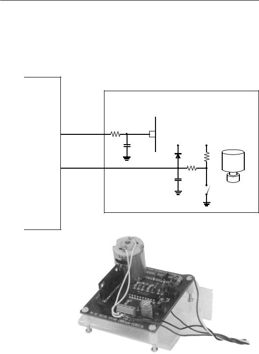
grounded. Therefore, during each rotation the top side of the switch would jump from 12 volts to 0 volts and back. This voltage is larger than the maximum input for the microcontroller, so the 12 volt square wave was clamped to a maximum high value with a resistor and a diode connected to the +5 volt power supply of the EVM11 board. The schematic diagram for this test setup is shown in Figure 5-2 and a photograph of the complete system is shown in Figure 5-3.
M6811C11EVM |
|
MC33033 - MPM3002 Motor Drive |
|
|
|
33033 |
|
OC1 |
PWM Output |
33k |
|
|
|
||
OC3 |
Pin g |
|
|
|
|
||
|
|
+5V |
12V |
|
|
1µƒ |
|
|
|
|
33k |
IC1 |
Time-Input |
|
|
|
|
|
|
|
|
|
8.2k |
|
|
.01 |
|
Magnet
Switch
Figure 5-2: Schematic Diagram of Motor Driver Test Circuit
Figure 5-3: Photograph Of
Assembled Motor Driver Test Circuit.

268 Chapter 5 Programming Large 8-Bit Systems
The program used to obtain the data in the above table was a slight modification of the motor control program listing given in Listing 5-6. The only change in this program was that the function @port void IC1_Isr(void) from Listing 5-7 was used. This routine stores in the location measured_period a value equal to the average of the last eight measured periods.
For several reasons, a reed switch is probably the worst example of an input sensor that you can find for a microcontroller. I chose this input because it is the poorest, and the result has been satisfactory. With reed switches, there are serious bounce problems on both the rising and falling edges of the signals. The life expectancy for a reed switch is relatively small, about ten million closures. During the course of preparing this text, I broke one reed switch and had probably a total of several hours of service out of the two used for these experiments. In practice, it is recommended that rotational measurements be made with optical interrupters. Do not, however, think that an optical interrupter is free from bounce problems. An optical interrupter will exhibit both bounce and also a relatively slow rise time. In such a case, it is necessary to use a software debounce technique and also an external Schmidt trigger circuit to create a quick and stable rise time that can be captured by the microcontroller.
The data for the above table were measured on the circuit shown in Figure 5-2. It was found that the PWM to voltage conversion was very accurate and repeatable with many changes in the system. For example, the prescaler value was changed from the value of 4 discussed above to 2 and up to 16. No difference could be noted in the PWM to voltage conversion over this range. Also, the input capture values were quite stable. The program in Listing 5-6 was compiled and used to complete the measurements. The PWM_count value was changed manually over the range of values shown above. The value for icap period is the value found in measured_period in the program. The voltage measured was the integrated value that was sent into the input of the MC33033 motor driver. The RPM was calculated as
60000
RPM =
measured_period
Data from this table are used to create an equation that relates RPM to the PWM_count. This equation will be used in the program to

Timer Operations 269
close the loop and regulate the motor speed. The relation that can be derived from the above data is
PWM_count= RPM +12528
7.875
This expression is accurate to about 1% across the range of interest. The measured data is the input capture count, which we will call p. What we must do is to calculate a new value for the PWM_count from a measured p. An error in p is called p and this expression means a change in p. The PWM_count will be designated as pc and also means a change in pc. We shall now attempt to arrive at an equation that expresses the necessary change in pc to correct for an error in p. The error in p is the difference between the desired cycle time and the measured cycle time. RPM in the above expression is converted to cycle time p by noting that the RPM is 60000 / shaft cycle time in milliseconds, and that the clock is ticking 500 times per millisecond. Therefore, we have
|
1 |
|
12528 +60000* 500 |
|
|
pc |
= |
|
|
|
|
|
p |
||||
|
7.875 |
|
|
||
If there is a error in the cycle time say, ∆p, then the change in pc, ∆pc, is seen to be
p |
+ ∆p = 1591+ |
3809500 |
|
p+ ∆p |
|||
c |
c |
||
|
|
This expression, after some simplification and approximation reduces to
∆p = –3809500 + |
∆p |
(5-1) |
|
c |
p |
2 |
|
|
|
|
|
This value calculated by the above expression will be used to change the PWM_count that drives the motor. The data contained in measured_period are placed there by the input capture interrupt service routine. It is assumed that the data there are always current.
The calculation to determine the PWM_count correction is substantial. We shall use this approach here to determine the correction, but recognize that there is another approach that probably requires less total calculation. This approach is to use a lookup table.

270 Chapter 5 Programming Large 8-Bit Systems
We will see the look-up table in some detail in Chapter 6.
We will probably run into overflow problems if care is not exercised in the calculation of the correction ∆pc. In Equation 5-1 above, p is the time of a shaft rotation in milliseconds. This number can vary from 1000 to 20000 depending on the motor speed. The best approach we could use is to divide the constant -3809500 by the value of p. Then multiply the result by ∆p and finally divide the result by p a second time. This approach will minimize the overflow problems. In the expression be low, p is the measured_period, pc is the PWM_count, and ∆p is the calculated difference motor_period - measured_period.
FOREVER
{
if(old_motor_speed!=motor_speed)
{
motor_period=30000000lu/motor_speed; old_motor_speed=motor_speed; PWM_count= ((motor_speed+12528)/63)*8; PWM_count=limit(PWM_count); delpc=(3809500/motor_period);
delpc=delpc*(motor_period-measured_period)/p; PWM_count -= delpc;
/* read in the motor speed; */
}
}
Recall that division by 7.875 is needed in the calculation of PWM_Count. This floating-point operation is avoided by dividing the expression by 63/8. Most often, floating point operations can be approximated by integer operations with sufficient accuracy.
It was mentioned earlier that it is possible to extend the maximum measurable time to something greater than the time required to clock the timer counter register 65535 times. If the longest time exceeds this value, the timer overflow interrupt can be used to an advantage. Suppose that you want to measure a long time with input capture 1. When this measurement is started, the value in the TCNT will be saved, and the timer overflow interrupt will be enabled. Also a counter will be reset to zero. In the timer overflow interrupt service routine, the counter will be incremented. Eventually, an input capture will occur, and the time between inputs is calculated as the time remaining

Timer Operations 271
prior to the first TOI, plus 65535 times the number of TOIs that have occurred, plus the time indicated in the input capture register. With a scheme of this nature, there is essentially no limit to the length of time that can be measured accurately. The resolution of this measurement is the time increment of the prescaler output.
A velocity servo is a particularly difficult application. Remember that velocity or motor speed is the derivative of position. Any derivative operation is prone to noise, and the successful servo must be carefully put together. For example, the equation calculated above to determine the feedback term is essential to the proper operation of the system. An interesting challenge is to try to duplicate the operation of the system described here with a normal gain type feedback. Even though the program seems to be messy, this approach will work, and most other approaches give you a wildly hunting or oscillating system. The calculation of the proper feedback value will avoid many of these problems.
Another problem area will be found. If the above FOREVER loop is allowed to run without any time control, the computer will be calculating a new feedback value many times before the effect of an earlier calculation will be seen in the system performance. This operation again causes the system to become unstable, and usually the system never finds the final value but hunts over some wide range around it. This operation can be corrected by slowing the rate at which feedback corrections are calculated. In particular, several rates have been tested, and it was found that a stable, accurate system would be obtained with a new feedback value calculated each quarter of a second. This time control is shown in the listing below. The main application program is broken into two parts: the first part is the code that will be executed whenever the motor speed is changed and the second part is the code that will alter the PWM_count which is the feedback portion of the program. The first portion is executed under the control of an if statement
if(old_motor_speed!=motor_speed)
There is no means to change the motor speed in this program, and this change will be introduced in the next section. Therefore, it is expected that the portion of the code controlled by this if statement will execute the first time the program is executed, and it should never be executed again until the system is reset. The second if statement
if(tick)

272 Chapter 5 Programming Large 8-Bit Systems
will execute its control code each time tick is TRUE. tick is ini tialized to TRUE when it is created, and it is set to FALSE each time the if (tick) routine is entered in the application program. If you go to the end of Listing 5-7, you will find that tick is reset to TRUE about each quarter of a second in the PWM timer routine. This sequence will cause the feedback calculation to be executed about each quarter of a second.
The initialization portion of the program shown in Listing 5-7 is little changed from that of the one shown in Listing 5-6. As mentioned above, we have added an application section that contains the calculations to control the motor speed. Also, there is one simple function that is used by the application section.
#include “hc11e9.h”
#define DIVIDE_8_SHIFT |
3 |
#define COUNT_8 |
8 |
#define COUNT_MAX |
3300 |
#define COUNT_MIN |
1600 |
#define COUNT_ONE_QUARTER |
32 |
#define PERIOD |
0X1000 |
#define TIME_ON |
0x0800 |
#define IMPOSSIBLE |
3500 |
#define TOO_LOW |
100 |
@port void IC1_Isr(void); @port void OC2_Isr(void); @port void OC3_Isr(void);
long limit (long);
long measured_period,delpc; WORD time1,time2, motor_period, motor_speed=IMPOSSIBLE;
WORD old_motor_speed=TOO_LOW,rpm,mparray[COUNT_8]; long PWM_period=PERIOD, PWM_count=TIME_ON;
int tick=TRUE,count=0;
main()
{

Timer Operations 273
/* The initialization portion of the program */ TCTL2.EDG1B=ON; /* capture falling edge only */ OC1M.OC1M7=ON; /* sent OC1 out to PA7 */ OC1M.OC1M5=ON; /* couple OC1 to OC3 */ TMSK1.OC3I=ON; /* enable the OC3 interrupt */ TMSK1.IC1I=ON; /* enable the IC1 interrupt */ OC1D.OC1D5=ON; /* turn on OC3 with OC1 */ TCTL1.OL3=ON; /* toggle OC3 when OC3 occurs */ PACTL.DDRA7=ON; /* make OC1 an output to PA7 */ TOC1=TCNT+PWM_period; /* set OC1 */ TOC3=TOC1+PWM_count; /* set OC3 time on */ cli(); /* enable the system interrupts */
/* the applications portion of the program */ FOREVER
{ /* All of the numbers used below are derived in the text */
if(old_motor_speed!=motor_speed)
{
motor_period=30000000Lu/motor_speed; old_motor_speed=motor_speed; PWM_count= ((motor_speed+12528)/63)*8; PWM_count=limit(PWM_count);
}
if(tick)
{
tick=FALSE; delpc=(3809500Lu/motor_period); delpc=delpc*
(motor_period-measured_period)/ motor_period;
PWM_count-=delpc; PWM_count=limit(PWM_count); rpm=30000000L/measured_period;
}
/* input the new motor speed */
}
}
/* functions of the main program */

274Chapter 5 Programming Large 8-Bit Systems
/* range of acceptable PWM_count is 1600 to 3300 */ long limit(long x)
{
if(x<COUNT_MIN) return COUNT_MIN;
else if(x>COUNT_MAX) return COUNT_MAX;
else
return x;
}
/* The asynchronous service portion of the program */
@port void IC1_Isr( void) /*the motor speed
measurement*/
{
static int i; int j; time2=TIC1;
TFLG1=IC1F; /* reset IC1 interrupt flag */ mparray[i]=time2-time1;
if (++i==COUNT_8)
{
i=0; measured_period=0; for(j=0;j<COUNT_8;j++)
measured_period += mparray[j]; measured_period >>= DIVIDE_8_SHIFT;
}
time1=time2;
TOC2=time2+5*measured_period/8; /*debounce time 5/8 revolution */
TMSK1.IC1I=OFF; /* disable IC1 interrupt */ TMSK1.OC2I=ON; /* enable OC2 interrupt */
}
@port void OC2_Isr(void) /* the debounce isr */
{
TFLG1=IC1F|OC2F; /* reset interrupt flags */

Timer Operations 275
TMSK1.OC2I=OFF; /* disable OC2 interrupt */ TMSK1.IC1I=ON; /* enable IC1 interrupt */
}
@port void OC3_Isr( void) /* the PWM isr */
{
TFLG1=OC1F; /* reset OC1 interrupt flag */ TOC1+=PWM_period;
OC1D.OC1D7 ^=ON;
TFLG1=OC3F; /* reset OC3 interrupt flag */ TOC3=TOC1+PWM_count; if(++count==COUNT_ONE_QUARTER)
{
count=0; /* enter the speed control */ tick = TRUE; /* about each quarter of
of a second */
}
}
Listing 5-7: Motor Control Program
In this program, dynamic debounce is used. In the function IC1_Isr() the debounce time is a calculated value rather than a mere 3 ms as was done in Listing 5- 6. Here the debounce lock-out time is five-eighths of the current measured period. This value goes beyond the half-way point in the input waveform enough to avoid any bounce that will occur during the rise time of the input signal. The remainder of this program is quite similar to that in Listing 5-6.
We have completed most of the application. The remaining parts of the program are to find a means to read into the microcontroller the speed that is desired for the motor, and to integrate and debug the whole program. Usually, the speed is established by some measure ment being done with the microcontroller. Let us approach the problem a little differently. Instead of making the speed a result of a measurement, let’s enter the speed into the part through the asyn chronous serial port.
Serial Communications Interface (SCI)
The SCI is another of the very useful peripheral functions found on the MC68HC11 family of microcontrollers. In fact, the SCI is
276 Chapter 5 Programming Large 8-Bit Systems
found on parts from all families of Motorola microcontrollers. The SCI performs the operation of a full function universal asynchronous receiver transmitter (UART). It can operate with most standard baud rates, and several nonstandard rates. Control of this peripheral is through the BAUD register, the SCSR (serial communications status register), and both SCCR1 and SCCR2 (serial communications control registers 1 and 2). There is one additional register called the serial communications data register. This register when written to is the transmit data register, and when read the receiver data register. Both the transmit and receive data registers are double buffered.
The BAUD register contains two test bits and two divide control registers that set the baud rate for the SCI system. The bits SCP control the baud rate prescaler. This prescaler has the unlikely prescale value of divide-by-13 when both bits are set. This value sets the maximum baud rate to 9600 when the system is driven by an 8 MHz clock. With this prescaler value, all of the standard baud rates from 9600 down to 150 are available to the SCI. The second divider is comprised of SCR. The bit patterns in these bits will select any power of two divisors between 1— 20 –and 128—27. For our system, we will choose 9600 baud, which is sufficiently slow that there should be few communications problems. The code to set up this baud rate is as follows:
BAUD.SCP=3;
BAUD.SCR=0;
These lines of code must be added to the initialization portion of the program to set up the baud rate to 9600 baud for the SCI system.
We will use the SCI system to read in the required motor speed for the program started in the preceding section. Such a system must be able to read in data through the SCI, but it must also echo the same data back to the originating source to provide full duplex operation. Therefore, both serial transmit and receive must be implemented. With the above system, there is no serious need to implement an interrupt driven system. The computer is clearly not being used to its capacity, so we will add the SCI input and output sequence to the applications portion of the code and feel safe that no input data will ever be lost because of an overrun error. (An overrun error occurs when a new input overwrites an old input before the old input is processed.) Therefore, none of the bits in SCCR1 need be changed from their reset value. In the SCCR2 register, there are two

Timer Operations 277
bits, transmit enable and receive enable, that must be set to enable the SCI. The following two lines of code will enable these bits.
SCCR2.TE=1;
SCCR2.RE=1;
These two lines of code must also be added to the initialization portion of the program.
The code to read the data in is as follows:
if (SCCR.RDRF==1) /* read in data if it is there */
{
new_character=SCDR;/*get new byte and reset RDRF*/ while(SCCR.TDRE==0); /* wait until transmit
buffer empty */ SCDR=new_character; /* send out byte and reset
TDRE */
}
This sequence of code does quite a bit more than you might expect. Before this code sequence can be executed, both the RDRF and TDRE flags must be set and reset. The RDRF is set when a character has been received by the SCI, and the TDRE is set when the SCDR is empty and can receive a character to send. Both of these bits are reset by the sequential read of SCSR with the bit set followed by a read for the RDRF or a write for the TDRE to the SCDR register. The above sequence accomplishes all of the proper bit resets, transmits the newly received character back to the sender, and leaves the new character in the location new_character . After receiving the data, the following sequence converts it into a binary number to be processed by the remainder of the program.
if (SCSR.RDRF==1) /* read in data if there */
{
new_character=SCDR;/*get new byte and reset RDRF*/ while(SCSR.TDRE==0); /* wait until transmit
buffer empty */ SCDR=new_character; /* send out byte and reset
TDRE */
/* if a number, process it */ if(new_character>=’0' && new_character <=’9')

278 Chapter 5 Programming Large 8-Bit Systems
new_speed = 10*new_speed + new_character-’0'; else if(new_character==’\r’)
{
/* reject any number out of range */ /* and start over again */
if(new_speed>=1000 && new_speed<=10000) motor_speed=new_speed;
new_speed=0;
}
else
new_speed=0; /* reject everything else */
}
The variable new_speed is initialized to 0 outside of this portion of the program. If the input character is a number (a number is any character that lies between ‘0’and ‘9’), it is converted from a character to a number when the character ‘0’ is subtracted from it. This value is added to ten times the value stored in new_speed , and the result is saved in new_speed . Repeated executions of this code sequence will convert a series of ASCII character numbers to an appropriate unsigned integer value. The entry sequence is terminated when a nonnumber character is received. If this character is a line terminator (a carriage return escape character in this case), the new speed value is put into motor_speed to cause the motor to change to the new value, and new_speed is reset to zero to await for the next input. If any other character is received, the data saved in new_speed is lost, and the whole entry of a new speed into the system must be repeated from the beginning.
In Listing 5-7 there was a lonely line of code
/* input the new motor speed */
That line has been replaced by the above and entered into Listing 5-8. The new motor speed input is placed in the main loop of the applications program, so a test is made each time through the loop to determine if there is a new input from the serial port. This routine also sends out the current speed of the motor once each half second. This output is controlled by the parameters tick1 and in_process. tick1 is set to TRUE each half second, and if in_process is FALSE the motor speed is calculated and sent to the serial port output.

Timer Operations 279
This sequence repeats each half second until in_process is set to TRUE. Whenever a character is read in through the serial port, in_process is set to TRUE to disable the continual output from the system while a new input speed value is being entered. If there is a new character in the input buffer, this character is read in and the RDRF flag is reset. The new character is immediately echoed back to the sending device as part of full duplex operation. If the new character is a digit it is processed, if it is a line feed it is also processed, and any number string is converted to an integer so that it can be used by the computer. The size of the number is tested to be certain that it is within the acceptable speed limits for the motor, and if it passes all of the tests, it is placed in the variable location motor_speed to indicate that a new motor speed is here and should be processed.
#include “hc11e9.h”
#define DIVIDE_8_SHIFT |
3 |
#define COUNT_8 |
8 |
#define COUNT_MAX |
3300 |
#define COUNT_MIN |
1600 |
#define COUNT_ONE_QUARTER |
32 |
#define COUNT_ONE_SECOND |
128 |
#define PERIOD |
0X1000 |
#define TIME_ON |
0x0800 |
#define IMPOSSIBLE |
3500 |
#define TOO_LOW |
100 |
#define RPM_MIN |
1000 |
#define RPM_MAX |
11000 |
#define CR |
0x0d |
#define LF |
0x0a |
/*function prototypes */ @port void IC1_Isr(void); @port void OC2_Isr(void); @port void OC3_Isr(void);
int putchar(char new_character); void dprint (unsigned int c); void do_crlf(void);
long limit(long );

280Chapter 5 Programming Large 8-Bit Systems
/* external variable definitions */ long measured_period,delpc;
WORD time1,time2, motor_period,motor_speed=IMPOSSIBLE; WORD new_speed;
WORD old_motor_speed=TOO_LOW,rpm,mparray[COUNT_8]; long PWM_period=PERIOD, PWM_count=TIME_ON;
int new_character,tick=TRUE,count=0,in_process; int tick1=TRUE,count1=0;
WORD got_new=TRUE; main()
{
/* The initialization portion of the program */
TCTL2.EDG1B=ON;/* capture falling edge only */ OC1M.OC1M7=ON; /* sent OC1 out to PA7 */ OC1M.OC1M5=ON; /* couple OC1 to OC3 */ TMSK1.OC3I=ON; /* enable the OC3 interrupt */ TMSK1.IC1I=ON; /* enable the IC1 interrupt */ OC1D.OC1D5=ON; /* turn on OC3 when OC1 occurs */ TCTL1.OL3=ON; /* toggle OC3 when OC3 occurs */ PACTL.DDRA7=ON;/* make OC1 an output to PA7 */ TOC1=TCNT+PWM_period; /* set OC1 to the period*/ TOC3=TOC1+PWM_count; /* set OC3 time on */
BAUD.SCP=3; |
/* set up the SCI */ |
BAUD.SCR=0; |
/* 9600 baud */ |
SCCR2.TE=ON; |
|
SCCR2.RE=ON; |
|
cli(); |
/* enable the system interrupts */ |
/* the applications portion of the program */
FOREVER
{
if(old_motor_speed!=motor_speed)
{ /* All of the numbers used below are derived in the text */
motor_period=30000000lu/motor_speed; old_motor_speed=motor_speed;

Timer Operations 281
PWM_count= ((motor_speed+12528)/63)*8; PWM_count=limit(PWM_count);
}
if(tick)
{
tick=FALSE; delpc=(3809500lu/motor_period); delpc=delpc*(motor_period-
measured_period)/motor_period; PWM_count -=delpc; PWM_count=limit(PWM_count); rpm=30000000L/measured_period;
}
/* input the new motor speed */
/* Send out the measured RPM to the terminal periodically */
if(tick1&&!in_process)
{
tick1=FALSE; rpm=30000000L/measured_period; dprint(rpm);
do_crlf();
}
if (SCSR.RDRF==ON) /* read in data if it is there */
{
in_process=TRUE;
new_character=SCDR; /* get new byte and save it */
while(SCSR.TDRE==OFF); /* wait until transmit buffer is empty */
SCDR=new_character; /* send out byte and reset TDRE */
/* got a number, process it */ if(new_character>=’0' && new_character <=’9') new_speed = 10*new_speed + new_character-‘0’; else if(new_character==’\r’)

282 Chapter 5 Programming Large 8-Bit Systems
{
do_crlf();
/*reject any number out of range */ /* and start over again */
if(new_speed>=RPM_MIN && new_speed <=RPM_MAX)
{
got_new=TRUE; in_process=FALSE; motor_speed=new_speed; new_speed=0;
}
}
else
new_speed=0; /* reject everything else */
}
}
}
/* functions of the main program */
/* the range of acceptable PWM_count is 1600 to 3300 */
long limit(long x)
{
if(x<COUNT_MIN) return COUNT_MIN; else if(x>COUNT_MAX) return COUNT_MAX; else
return x;
}
/* send out a single carriage return-line feed sequence */
void do_crlf(void)
{

Timer Operations 283
while(SCSR.TDRE==OFF);
SCDR=CR;
while(SCSR.TDRE==OFF);
SCDR=LF;
}
/* send a single character to the serial port */
int putchar(char new_character)
{
while(SCSR.TDRE==OFF);
/* wait until transmit buffer empty */ SCDR=new_character;
/* send out byte and reset TDRE */
}
/* convert an integer and send it to the serial port as a string */
void dprint (unsigned int c)
{
if ( c/10) /* recursively determines if */ dprint(c/10); /* a zero has been reached and then */ putchar(c%10+’0'); /* sends out the characters */
}
/* The asynchronous service portion of the program */
@port void IC1_Isr( void)/*the motor speed measurement*/
{
static int i; int j; time2=TIC1;
TFLG1=IC1F; /* reset IC1 interrupt flag */ mparray[i]=time2-time1;
if (++i==COUNT_8)
{
i=0;

284 Chapter 5 Programming Large 8-Bit Systems
measured_period=0; for(j=0;j<COUNT_8;j++)
measured_period += mparray[j]; measured_period >>= DIVIDE_8_SHIFT;
}
time1=time2;
TOC2=time2+5*measured_period/8; /*debounce time Is 5/8 revolution */
TMSK1.IC1I=OFF; /* disable IC1 interrupt */ TMSK1.OC2I=ON; /* enable OC2 interrupt */
}
@port void OC2_Isr(void) /* the debounce isr */
{
TFLG1=IC1F|OC2F; |
/* reset interrupt flags */ |
TMSK1.OC2I=OFF; |
/* disable OC2 interrupt */ |
TMSK1.IC1I=ON; |
/* enable IC1 interrupt */ |
}
@port void OC3_Isr( void) /* the PWM isr */
{
TFLG1=OC1F; |
/* |
reset OC1 |
interrupt |
flag |
*/ |
TOC1+=PWM_period; |
|
|
|
|
|
OC1D.OC1D7 ^=ON; |
|
|
|
|
|
TFLG1=OC3F; |
/* |
reset OC3 |
interrupt |
flag |
*/ |
TOC3=TOC1+PWM_count; if(++count>=COUNT_ONE_QUARTER)
{
count=0; |
/*enter speed control about */ |
tick=TRUE; |
/*each quarter of a second */ |
}
if(++count1==COUNT_ONE_SECOND)
{
count1=0;
tick1=TRUE;
}
}
Listing 5-8: The Completed Application