


134 Chapter 3 What Are Microcontrollers?
exactly those peripherals required. The smallest microcontroller has only a 15-bit timer, and the most complete MC68HC05 part has everything but a SPI system. All varieties in between these extremes exist. In the larger chips, some of the basic requirements for the microcontroller change. We will see these larger chips in later chapters.
Programming Microcontrollers
The preceding brief description of what microcontrollers are gives a rather bleak picture of a potential programming environment from a computer standpoint. Most programmers are used to having an operating system that handles such mundane things as I/O, memory management, time management, program loading, error processing, interdevice or intertask communications, and so forth. Be prepared for a giant step backwards when you address the microcontroller. There is usually no operating system, no libraries of useful functions, no I/O handling, nothing but a bare-bones computer with a bunch of hard-to-tame peripheral components onboard the single-chip device.
C compilers for the microcontrollers have been available long enough that they are thoroughly tested and do a good job of creating proper code. Anyone who has programmed a microcontroller in assembly language knows that the programs must be very direct and have no fancy overhead. Memory is strictly limited, and the compiler must generate assembly code that is as resourceful as can be created by any thoroughly qualified assembly language programmer for the machine.
The development environment, while quite sophisticated in terms of how it works, does little for the programmer in terms of direct help in debugging a program. There are two different types of development systems that are in common use. Both of these systems require a host computer to run the device. The simplest of these systems goes by names like evaluation module, evaluation system, or evaluation board. These devices are usually board-level products that require a power supply in addition to a host computer.
The software to run the development boards is merely a good terminal emulator. Assemblers and linkers for the different chips are provided as part of the development board. The programmer writes the code for the part in the host computer. This code is assembled, compiled, and linked in the host computer. The code is then

Programming Microcontrollers 135
down-loaded to the development board through either a serial or a parallel link depending upon the individual system.
The development board has the microcontroller that is to be emulated on board. This microcontroller sometimes operates in a nonuser mode that allows internal bus access. A second computer on the development board controls the operation of the microcontroller. Code delivered from the host is put into memory accessed by the microcontroller, and the microcontroller can operate as if the code were contained within its internal memory.All of the I/O lines associated with the microcontroller are brought to a header on the development board, and a cable can be attached to this header to a plug-in device that plugs into a target board. This target system then operates as if it had a programmed microcontroller plugged into its socket.
The microcomputer on the development board has a complete monitor system in its firmware. This monitor provides communications with the host, down-loading and up-loading capability and, most important, complete debugging firmware for the microcontroller.
There is a single line assembler and disassembler in the firmware. This package allows the programmer to examine and change memory in assembly mnemonics. The microcontroller program can be single stepped, run, address breakpointed, and the memory can be displayed in normal hexadecimal format. The microcontroller runs at full speed when emulating operation in a target board.
An experienced programmer will be able to debug code in a microcontroller with the help of such a development board. There is additional software available that provides a nice display of all pertinent information in a single screen on the host computer. In this area, you will also find that the microcontroller can be controlled from a display of C source code on the host computer. This technique is called source level debugging.
On later chips, another feature is incorporated to help the development environment. This feature is called Background Debug Mode, or ONCE. Both of these similar operations allow debug to take place in an external computer without any access to the microcontroller resources such as interrupts or memory. When a chip is put into BDM, certain pins become a special serial input/output port. There are several commands that can be delivered to this port from an external computer. These commands allow the computer to
136 Chapter 3 What Are Microcontrollers?
set memory, examine memory, examine registers, set and clear registers, execute code, set and clear break points, and so forth. All of the operations normally needed to debug a program can be executed through this special serial port. There is no need for an on-board monitor on the microcontroller, and it is not necessary to make use of the chip interrupts by the debugger during the debug operation. All of the programming needed for the debugger can reside in a host computer. Most modern chips have this type of interface, which greatly simplifies debugging of microcontrollers.
All of the above capabilities are available with the development boards. Another level of capability is available. These devices are box level, and usually have a built-in power supply. Most development systems require a host computer, and usually they come with special software to interface with the host computer. These systems have all of the capabilities outlined above plus some significant improvements. The breakpoint capability of these systems is much improved over the simple address breakpoint above. Here a complicated breakpoint can be employed that will break the program operation on read or write, at any data or address location, on access of data or program, or access of a range of data or address locations. Also, the breakpoint can occur after a specified number of occurrences of the breakpoint conditions.
Another major difference in the development systems is the trace buffer. A trace buffer is a memory that is as many as 48 or 64 bits wide. Each clock cycle of the microcontroller, the condition of all address bits, the data bus, the internal microcontroller control bus, and as many as 16 external test point lines are captured in the trace buffer.
Usually, the trace buffer is 4 to 16 kilowords deep, so it can hold a significant number of microcontroller clock cycles. Even if the microcontroller is running slowly, one million clock cycles per second, such a trace buffer represents an insignificant execution time. To help make the data contained in the trace buffer, trace buffer capture can be controlled by a system that is the same as the breakpoint operation. Therefore, the portion of the program that is traced is under the detailed control of the programmer.
The data in the trace buffer can be displayed in several different manners. The simplest, of course, is to print to the computer screen the I/O pattern of all the lines captured. This type of display is extremely difficult to interpret, but it is useful in some cases. To help the programmer determine where the microcontroller is operating, it
Coding Tips for Microcontrollers |
137 |
|
|
is possible to read the data bits and display a disassembled version of the code being read into the microcontroller. This display is also quite useful in debugging the code.
Yet another display is called a logic analyzer. A logic analyzer is an oscilloscope display that shows the logical status of the various lines captured in the trace buffer. A logic analyzer is a separate device, but it can have a built-in disassembler that displays the disassembled code along with the condition of the designated lines.
The devices with logic analyzers and trace buffers are quite a bit more expensive than the development boards discussed earlier. Some of the development systems provide source level debugging capability for high-level languages like C.
Another approach to development systems has been made available in some of the newer microcontrollers. The microcontrollers from the MC68HC16 family and those from the MC68300 family all have a background mode of operation. When operating in the background mode, these chips stop their normal computing and start serial communications with an external computer. The background mode can be entered as the result of an internal command or an external signal. There are enough debug commands that can be communicated over this port to allow complete debug of any program that the microcontroller might be running. Minimum external circuitry is needed to support the debug mode, so these high-powered chips can operate as their own development environment. Here, the development support is mostly software contained within the host computer, and the deliverable system can contain all of the essential components of a development system.
Coding Tips for Microcontrollers
One of the major tasks facing a programmer when writing code in a high-level language for any microcontroller is to make the resulting program as readable as possible. Other people who might later need to read or modify your code must be able to understand what is going on in your program. It is extremely important that mnemonics be used as much as possible when dealing with various registers, their bit contents, and special memory addresses throughout your programs; otherwise, the resulting code will be a “quasi-C” program filled with many numbers and funny-looking cast operations that will be largely incomprehensible to others trying to maintain your program.

138 Chapter 3 What Are Microcontrollers?
Modern large 8-bit systems are very nearly as complete as yesterday’s mini-computers. Programs for microcontrollers are also getting large, and they are increasingly being written by a team of programmers instead of a single programmer. The management of the programming task is much more important when a team is involved because the person-to-person interface is the most “dangerous” in all programming. It is easy for people to make mistakes; misspelled words, interchanged order of parameters in a function argument, passing incorrect data to a function, etc., are all problems that can (and often will) arise when several people try to write a single program. Each person on the team can probably keep a maximum of six or seven function interfaces in mind, and even then mistakes will be made. When the program is really large, there will be dozens of function interfaces and sources of possible error will abound. For example, most of the time programmers will try to use what is in mind rather than look up a questionable function call.
How can these problems be minimized? Fortunately, there are several steps you can take to keep errors down to a manageably low level. A big one is to make certain that an ANSI-certified compiler can be used for any program and that the computer will enforce strict type checking in the program. This will cause most of the errors due to carelessness or simple accidents to be caught at compile time and not during the debugging phase. If such errors are not caught by the compiler, they are among the most difficult to find when they show up at run time. Programs can be improved by following these conventions:
1.Use a consistent constant definition naming convention. Use all capital letters for the names of constants defined in #define statements.
2.Make all function names thoroughly descriptive. Use several words for each name if possible, and capitalize the first letter of each word so that the words can be distinguished easily. For example, a function that returns the time should have a name like
TimeOfDay() or Time_Of_Day(). The important thing is that the name describe the function in some detail. Be consistent with naming conventions. If you start with names having no un derscores, keep this convention throughout the entire program.
3.Make use of typedef and the fact that structures create new types. Where possible, create a type that is descriptive to your program. For example, in the C language the interface to all input/output and
Coding Tips for Microcontrollers |
139 |
|
|
files is through the type FILE. FILE in this case is simply a type that has been made available to the program through a typedef statement of a structure that contains all of the essential elements needed for file input/output. It is recommended that types created by typedef statements involving a structure should have names with the first letter capitalized. The names of these types should be brief and should be one word only.
4.The C macro gives us the ability to create functions that will be compiled in-line. This is very useful, but remember there is no type checking for macro defined functions and you do not know what will be returned from a macro function. This does not mean to avoid macro functions, but it does mean that with no type check ing we have a part of the program that does not get the normal scrutiny we expect with most function calls. Be careful when us ing macros—you, not the compiler, must make certain that the argument types and the return type are all correct.
5.Use as few global variables as possible. Global variables seem to be an easy way to avoid using function arguments, but they also can make debugging extremely difficult. Parameters should be passed to functions as arguments. This approach will give the programmer some assurance that compile time checking will catch any typing errors, and will eliminate the problems of “side ef fects” found with global variables.
6.Be consistent. When designing function calls, make the order of the parameters in the argument list logical and be consistent throughout the whole program.
7.Avoid complicated argument lists. If it becomes necessary to send many variables to a function, create a structure that contains all of the arguments and send a pointer to the argument structure as a param eter rather than the arguments themselves. Since the members of the structure are all mnemonics with—hopefully!—meaningful names, the filling of the structure should result in a more accurate creation of the parameter list than would be found if the parameters are all listed in the function argument.
8.Be courteous—document your code. There is no need for a com ment for every line of code, but it is unconscionable that a program should go page after page with no comments. Every function

140 Chapter 3 What Are Microcontrollers?
should have a comment header that explains what the function does in the program. The header should contain a list of the func tion arguments and a record of modifications to the function. If there is some nonobvious code in the program, this code should be documented to explain what is happening.
9.Kernighan and Ritchie, the developers of C, gave us a language that is rich with shorthand notation. While often useful, this is a tool that can be badly misused. Don’t write code in a convoluted manner using tricky shorthand notations so that nobody can un derstand what you’re trying to do. You might be the one who has to maintain the resulting code a decade later!
10.Always create mnemonics for addresses and bit variables used in the program.
11.Use assembly language only when C cannot accomplish neces sary operations.
12.Microcontrollers usually work with unsigned variables. Often the microcontroller can create more efficient code when doing compares with unsigned variables. Therefore, use unsigned variables every where unless it is necessary to use signed variables. A few typedef operations will help keep the use of unsigned variables in mind:
typedef WORD unsigned int; typedef BYTE unsigned char;
In writing code for a microcontroller, you must be able to deal with ports at some specific address location, the bits within these ports, control registers, certain data registers, and other important control functions. The program can be easily written if the names of all registers, ports, bits, and so forth are taken from the component specification and not made subject to the whim of the programmer. Therefore, if all of the ports and bits have the name given in the microcontroller reference manual, then any variable used will be defined in one place and the programmer need only find the appro priate register along with the definition of its bits in the reference manual to understand what is being done in the program. The refer ence manual becomes part of your documentation.
We saw back in Chapter 2 how to create mnemonics for address locations. It is necessary for programmers to write a series of define
Coding Tips for Microcontrollers |
141 |
|
|
statements which identify all of the register locations, port addresses, and bit names for the microcontroller. It is best if all of these pre liminary data are placed in a header file specific to a device and then it can be included at the beginning of programs for the device. This approach is convenient because it gives the programmer the ability to use mnemonics throughout the program. It also provides some limited portability. If a second device in the same family has some what different register and port locations, it is possible to write a new header file for this second device and code written for the original device will probably work with the second device when the proper header file is included. We will discuss header files further as we examine the programming of specific microcontrollers.
In this book, you will see the C programming language used to develop code for embedded systems products. C is a powerful language that can be abused and is often the subject of such abuse. Don’t abuse this fine language. It is your responsibility as a programmer to write code that is easy to read, easy to understand, easy to debug, easy to maintain, and easy to use. Any fancy antics in coding are uncalled for and not needed. Any group that is writing project code should implement a shop coding standard that will direct the way code is written. There are several organizations that have prepared such standards. I cannot agree with all of the elements of these coding standards that I have seen, but any coding standard is better than none. Research the matter and find a coding standard that comes close to suiting your needs and then modify it to meet your needs exactly. And then use it.
I previously mentioned “group development.” I have seen many small projects in which the software development was an afterthought. There are still many projects that can fit into a few hundred bytes or even a few thousand bytes. Such projects might not seem to require the careful oversight implied by a shop standard. But they do! In the development of software, you will find that the initial cost of the software is dwarfed by the cost of maintenance. Therefore, any effort put forth to help the maintenance of the software into the future is effort well spent regardless of the size of the project. You will often find that newer chips have massive memory spaces and with these memory spaces available, the code will expand to fill them. This expansion of the code is not necessarily bad if the expansion accompanies improved operation and features. However, one

142 Chapter 3 What Are Microcontrollers?
implication is that the one hardware engineer in the lab can no longer be expected to develop the code for such projects. More and more teams are coming together to develop embedded systems software today. Such teams almost demand that a coding standard be in place if the code thus generated is to ever be useful.
Testing
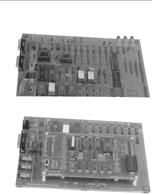
In future chapters we will see many programming examples de veloped. The code in such examples has been tested and runs on the microcontroller it was designed for. The hardware interface used to test these programs has been a series of evaluation boards built by Motorola. The several different boards used each represent a differ ent approach to an inexpensive development environment. For the MC68HC05 family, I used the MC68HC05EVM and MC68HC05EVS series. The EVM is an evaluation module for many of the older MC68HC05 family of microcontrollers. This family grew so large and so many different devices were introduced into the prod uct line that it was impossible for a single board to provide the development services needed for the whole family. A new series des ignated as the EVS family was developed to meet these expanding needs. The EVS is comprised of a base board with many of the needed interface components. A daughterboard containing all of the “com ponent unique” capability of the system is plugged into the base board.
These systems provide excellent development environments. Each system contains a microcontroller of the type being developed. In the case of the MC68HC05 family, the on-board components are operat ing in a special mode called the non-user mode. In the non-user mode, the device reorganizes its pins to provide an expanded bus operation so that memory and external control can be used on what is usually a single-chip microcontroller. For these parts, a special chip is used called a port replacement unit, or PRU, which is put onto the expanded bus, and its outputs are exactly the same as what would be seen on the ports if the chip were operating in the normal mode. With this capability, RAM can be substituted for internal ROM on the microcontroller and the software implications of this change are unlimited. For example, programs can be loaded into the memory at will, memory access breakpoint can be implemented, the program can be started at any point, the contents of the memory can be changed, and so forth.
Coding Tips for Microcontrollers |
143 |
|
|
A firmware monitor is placed on the evaluation board. A serial port is added, and the board, under the control of the monitor, communicates with a host computer. As a matter of fact, the host need only be a terminal in the most basic case. The monitor provides several important debug and development functions. Code can be downloaded from the host computer into the memory of the evaluation board. The monitor contains a single line assembler/disassembler module. With this software available, the user can examine the code in the microcontroller memory in either hexadecimal or mnemonic form. Also, memory contents can be changed in either hexadecimal or mnemonic form. Breakpoints can be inserted into the code, and the operation of the program can be observed from the terminal of the host computer.
In addition to the evaluation capability of these boards, they also each have extension headers that allow the board to be plugged into a target system. When operated in this manner, the target system operates as if it has a programmed microcontroller in its socket. Of course, the code in the microcontroller is that in the memory on the evaluation module. The emulation of the microcontroller in this case is excellent. The microcontroller on board the evaluation module is executing the code for the target system. The microcontroller re sources used in the target system are those found on board the microcontroller in the evaluation module. In most cases, the lines connected to the target system are connected directly to either the evaluation module microcontroller or PRU. The PRU is designed to emulate the pin operation of the microcontroller as well as possible. Therefore, the loads presented to the target system by the emulator and the signal responses of these pins very nearly duplicate those of the microprocessor being emulated.
Figures 3-2 and 3-3 are photographs of the MC68HC05EVM and the MC68HC05EVS, respectively. Note that Figure 3-2 shows a single-board system while Figure 3-3 shows a two-board device. All of the development devices discussed here require an external power supply. Any device suffixed “EVM” needs a +5 volt supply as well as +12 and -12 volt sources. The higher voltage supplies are needed only to drive the RS232 communications signals necessary to com municate with the host computer. On the EVS and the MC68HC16EVB boards, only a +5 volt supply is needed. Most of the components being emulated by these boards can have some on
144 Chapter 3 What Are Microcontrollers?
board nonvolatile memory, such as EEPROM or EPROM. The evalu ation boards each provide a means of programming these memories. Usually, a high voltage is needed. This voltage will vary from part-to-part and it must be applied as a separate voltage on the board.
Figure 3-2: MC68HC05EVM Single Board Development System.
Figure 3-3: MC68HC05EVS Two-Board Development System.
Coding Tips for Microcontrollers |
145 |
|
|
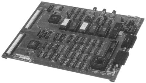
The previous discussion is aimed at the MC68HC05 development boards. The MC68HC11 also has an EVM. This EVM operates ex actly the same as that discussed above. There are several EVMs for the different parts in the MC68HC11 family. Figure 3-4 shows a photograph of the MC68HC11EVM.
Figure 3-4:
MC68HC11EVM Development System.
In all of the devices we’ve discussed, communication with the host computer is through an RS232 serial link from the board. The development work can be done with a terminal emulator on the host computer. Such a terminal emulator might be found in the software programs PROCOMM or KERMIT. Certainly, any terminal emulator can do the job, and those mentioned here are just two of many.
Development through a simple terminal emulator is usually not the easiest approach. Motorola ships a software package with each evaluation device. This software package is written by P & E Micro computer Systems, Inc. It provides a “windowed” environment that shows the conditions of many internal features of the device being evaluated. All of the internal microcontroller registers are displayed, a listing of the breakpoints that have been set are shown, a block of the code being debugged is displayed, and a control screen is also available. The display will differ with various devices, but in general the screen interface is easy to use and understand.
146 Chapter 3 What Are Microcontrollers?
In some cases, a complete symbolic debug environment can be es tablished. P & E Microcomputer Systems, Inc., has a file system that allows transfer of source code to the program. This source code is displayed in the code window. It helps during the debug procedure to see the source code while stepping through it. This capability is avail able with the compiler used for the MC68HC05, but not for the MC68HC11 and MC68HC16 families.
All of the software written by P & E runs under the DOS operating system. Today, there are fewer computers that run under DOS than in the past, so you might want to find a later development system that runs under a more modern operating system. I have always used DOS by itself or running under either Windows 3.1 or one of the later Windows operating systems. During the availability of OS/2, it was an ideal operating system to develop microcontrollers under these DOS-based development systems. More recent systems require Windows 95 or later.
Development is enhanced if the host computer has multitasking capability. This capability can come from any of the popular operat ing systems, such as Microsoft Windows or X Windows. In such a case, it is possible to keep an editor with the listing file of the pro gram being debugged in a window along with the P & E display in another window. This approach provides both insight into the code being developed along with the condition of the hardware as the ex ecution of the code proceeds. It is recommended that this approach be used when debugging programs on evaluation boards.
Unfortunately, none of these evaluation boards allows access to the operation of the component being debugged when the device is executing the test code. To achieve this level of operation would in crease the complexity of the development board significantly. Also note there is no provision for a trace buffer on these boards. The newer boards, EVS and MC68HC16EVB, provide headers that can be connected to a logic analyzer that can act as a trace buffer and provide many of the functions usually found in the more compre hensive development devices.
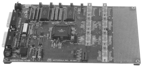
One last development device used is the MC68HC16EVB, shown in Figure 3-5. This board differs from the others in one significant way. The MC68HC16 family of devices (as well as those found in the MC68300 family) provide a capability not usually found in most
Coding Tips for Microcontrollers |
147 |
|
|
microcontrollers. These devices can be placed into a background debug mode that facilitates development of the code. In all of the above development boards, the monitor software must execute on the microcontroller being developed. This operation means there must be either memory bank switching or the monitor must occupy some of the normal memory space of the microcontroller. In either case, the presence of the monitor software can be seen in the operation of the microcontroller. Also, development with the above systems will require that other resources be used for the development operation. For example, if control of the development is through a serial port to a terminal, the SPI of the microcontroller will probably be used. In the background debug mode (BDM) of the larger devices, this memory and resource sharing between the monitor and the code being de bugged is unnecessary. When a device is placed into BDM, its normal operation ceases and all communications with the device occurs through a special serial port. Through this serial port, the condition of the device can be examined, memory can be accessed and changed, breakpoints can be established, etc., just like the invasive technique. However, when the device is returned to operation, there is no way the presence of the monitor can be seen by the running program.
Figure 3-5: MC68HC16EVB Development System.

148 Chapter 3 What Are Microcontrollers?
With BDM, all debug software can be placed on a host computer. Therefore, it is possible to write much better debugging systems that connect through the BDM system. Most recent microcontroller chips employ some type of background debug mode operation. It is not always called BDM. It might be called ONCE or JTAG, but these operations are basically similar and allow background debugging of the microcontroller and a host to contain all of the necessary debug software.
Another advantage to using the BDM is that all communication between the host and the device is through an 8-wire bus. This bus can be accessed in any device, so these devices become their own development systems and no development system is really needed to work on the final target system.
The MC68HC16EVB uses the BDM operation. Communications with the host computer are through the parallel, or printer, port on the computer. P & E has written an interface for “PC clone” computers that uses the parallel port. Its operation is essentially as for the MC68HC05EVM and MC68HC11EVM devices. P & E has also made an additional device which can connect to the 8-wire BDM bus and connect directly to the host computer parallel port. It requires a +5 volt power source and takes its voltage through the lines to the target system.
Three other chips will be examined in the following chapters. The M68HC08 family and the M68HC12 family are extensions of the M68HC05 and the M68HC11 families, respectively.Yet another recent chip family is the MCORE. These RISC chips are very fast and run at extremely low power. The MMC2001 chip from this family will be examined. The development system for the MCORE chips is called an EBDI—Extended Background Debug Interface. This package is interfaced to an evaluation board through an 8-wire serial port.
All of the programs in the chapters that follow were tested on the appropriate development boards. These programs are relatively small because each is designed to show some feature of either the microcontroller or the language as applied to the microcontroller; larger programs were not appropriate to the tutorial aims of this book. With judicious use of the boards along with the development environment on the host computer, these programs were easy to develop and debug.

Chapter 4
Small 8-Bit Systems
Not surprisingly, writing code for any microcontroller—whether in assembly language or a high-level language like C—requires a detailed knowledge of the microcontroller being programmed. Usu ally, a high-level programming language requires little knowledge of the underlying computer on the part of the programmer. This ap proach allows the programmer to concentrate on the nature of the problem being solved rather than how to squeeze the problem into a specific computer. A C abstract computer has been designed and you write code for this computer when you write C code. The abstract computer has no registers, control registers, index or address regis ters, or any other of the normal resources found on a typical computer. The language is sufficient to allow proper creation of code needed to run the core computer. However, the essence of any microcontroller is the special on-board peripherals that it provides. These peripherals are not directly available from the C language either.
Programming techniques must allow use of these peripherals or the high-level language is valueless. Three distinct levels of microcontrollers will be covered in different sections of this text. The simplest microcontroller is embodied in the M68HC05 family. These 8-bit devices are usually completely self-contained and do not support an expanded bus.Another level of complexity is found in the M68HC08, the M68HC11 and the M68HC12 families. These computers are also 8-bit machines, but they have more registers than the M68HC05 fam ily and support an expanded data bus. With the expanded data bus, these families can have external memory and peripherals in addition to those within the chip itself. (The peripherals on these chips are not very different from those found on the M68HC05.) The step up in computer power is the M68HC16 microcomputer. This computer is a
149

150 Chapter 4 Small 8-Bit Systems
16-bit machine and its peripheral components are nearly all different from those found on the 8-bit machines. The M68HC16 is a superset of the M68HC11; it will execute M68HC11 code, but the hardware computer extensions and new peripheral components are significant.
To successfully program a microcontroller using a high-level lan guage, the programmer must be able to access various control and status registers in the computer. The program must force the language to place both program and data memory addresses in the proper locations in the memory map. Vectors associated with interrupt service routines, and the service routines themselves, must be handled directly by the program. These tasks are difficult to accomplish with most high-level languages, but C allows access to these things without extensions. However, most C compilers for microcomputers have extensions that allow such special features to be easily treated.
The compiler used in this chapter is called C68051. It was written to support the M68HC05 family of devices. Be forewarned: some M68HC05 microcontroller instructions have no counterpart in the standard C lan guage. Special directives identify unique microcontroller characteristics to the compiler. Listed in Table 4-1 below are nine assembly instructions available to the 68HC05. These instructions have no equivalent C call. They can be accessed as either a single instruction (all uppercase) or as a function call as shown. The function call requires a pair of closed parentheses to follow the name of the instruction.
Function |
Operation |
CLC or CLC() |
clear carry bit |
SEC or SEC() |
set carry bit |
CLI or CLI() |
clear interrupt flag (interrupts on) |
SEI or SEI() |
set interrupt flag (interrupts off) |
NOP or NOP() |
no operation |
RSP or RSP() |
reset stack pointer |
STOP or STOP() |
STOP instruction |
SWI or SWI() |
software interrupt |
WAIT or WAIT() |
WAIT instruction |
Table 4-1: Assembly Codes Directly Callable By C6805
1 Byte Craft Limited, 421 King Street North, Waterloo, Ontario, Canada N2J 4E4

Small 8-Bit Systems 151
A pragma is a C preprocessor command not defined by the lan guage. As such, the compiler writer can use the #pragma command to satisfy a need not specifically identified by the language. C6805 uses pragmas to identify microcontroller-specific characteristics. Table 4-2 contains a list of pragmas used by C6805. The format of a pragma directive here is
#pragma portxx portname @ address
where portxx can be portr, portw, or portrw which shows whether the port is read, write, or both. portname is the name used in the program for the port. The at symbol (@) identifies a memory address. #pragma mor identifies the contents of the masked option register used on field programmable chips. There are some instruc tions that are not found across the whole M68HC05 family. In particular, some devices may not have the MUL, the DIV, the STOP, and the WAIT instruction. The #pragma has a preprocessor call that identifies the instructions from this set in the particular microcontroller.
pragma |
Function |
#pragma portxy |
I/O port definition |
#pragma memory |
RAM/ROM definition |
#pragma mor |
mask option register |
#pragma has |
instruction set options |
#pragma options |
compiler directives |
#pragma vector |
interrupt vector definitions |
Table 4-2: C6805 pragma Directives
This compiler has certain options that can be inserted from the command line or, if needed by the programmer, the #pragma op tions preprocessor command can also be used to set the appropriate compiler options. Finally, the #pragma vector identifies a given function name as an interrupt service routine. When the compiler com piles the name specified, it will place the address of the function into the defined vector location. Another modification in the compiled code will take place when #pragma vector is used. All returns from a function identified by a vector pragma will use the return from in terrupt instruction rather than the usual return from subroutine.

152 Chapter 4 Small 8-Bit Systems
Another useful directive pair is the #asm and the #endasm. The code enclosed in a block that starts with #asm and ends with #endasm must be in standard assembly language. Variables defined in the C program can be used safely.
C can accomplish almost everything that the assembly lan guage program can. You will find that the C6805 compiler will create tight, efficient code that is probably as good as can be written by a competent assembly programmer. There are, however, some items that are absolutely foreign and inaccessible to a compiler. A compiler cre ates code for an abstract machine that does not exist in reality. The usual registers found in the real machine are nonexistent in the abstract machine. For example, it is not possible to access the status register of the microcontroller with compiled code. Usually, status register con tents are not directly important to the conduct of the program. But later we’ll see an example where the ability to manipulate the carry bit of the status register can save many bytes of code. Therefore, it is important to be able to use some assembly code as well as C.
This chapter will concentrate on small 8-bit microcontrollers. Subsystems such as timers, analog-to-digital converters, computer operating properly (COP) timers, etc., found on the 8-bit systems will be outlined and their programming discussed. While the main details of the central processor in the microcontroller are important to the assembly language programmer, they are of little interest to the C programmer. This observation is true at least at the C level. If it becomes necessary to enter an assembly language program for opti mization of code size or other considerations, then the programmer is required to have detailed knowledge of the programming model and the internal architecture of the computer.
Let’s start by discussing important microcontroller peripheral components that you can expect to find. We’ll begin with what is probably the most important single consideration in the selection of a microcontroller to do a job—the device memory. This discussion will be followed by sections on other important peripherals such as timers, analog-to-digital and digital-to-analog converters, serial com munications devices, and simple digital input/output lines.