

166 Chapter 4 Small 8-Bit Systems
compile individually and examine if they create outlandish code. Once these small functions are all debugged, you can integrate them into your program as either inline code or as function calls. Hence, the fundamental rule of writing good high-level code for a microcontroller: the production of good C code for a microcontroller is a joint effort between the programmer and the compiler writer.
Erasure of EEPROM causes component wear, and most EEPROMs will wear out after a large number of erasures. The nature of the deg radation is that the component refuses to erase after many erasures. There has been no evidence that data retention is affected by repeated erasures. The number of erasures that can cause problems is tempera ture sensitive. Most of these devices are rated for 10,000 write/erase cycles at the maximum rated temperature for the part. At room tem perature, the number of write/erase cycles without damage can grow to several hundred thousand. In light of these facts, it is important that programs use care in rewriting the contents of EEPROM.
EXERCISES
1.The EEPROM in microcontrollers erase to the 1 state. Write a function that checks to determine if an erasure cycle erases the contents of a given location in memory.
2.Write a function that compares data to be programmed into EEPROM and determine if it is necessary to erase a byte contain ing data before it is reprogrammed. This approach will extend the life of the EEPROM.
Timers
The systems of timers placed on microcontrollers are among the most creative engineering efforts most people will ever see. The func tions of these timers cover literally dozens of different operations. This set of peripheral components mainly relieve the computer of much work associated with execution of the peripheral function. We will start with the simplest timer and outline different timer capabili ties in increasing complexity. The most basic timer in the M68HC05 family is called the 15-bit timer, and probably the most advanced timer system is the 16-bit timer. These different timer systems are literally unrelated in the features they offer. Another timer feature

Timers 167
offered in some microcontrollers is the computer operating prop erly (COP) timer. Each of the systems will be examined in some detail in the following paragraphs.
Multifunction Timer—15-Bit Timer
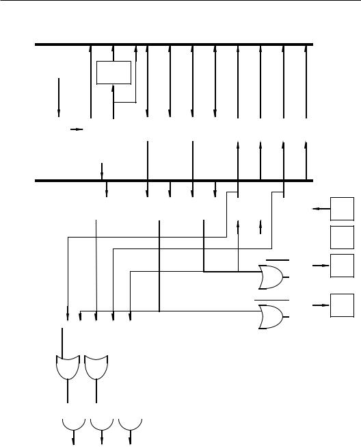
A timer of this nature can be found on the smallest of the M68HC05 components, such as the M68HC05J1 or the M68HC05P8, and it is not found on the M68HC05Bx devices discussed previously. This timer consists of an 8-bit ripple counter followed by an addi tional 7-bit counter. This counter chain is driven by a signal that is at one-fourth the internal clock frequency of the microcontroller. The internal clock frequency in turn is half the crystal frequency. This portion of the counter is completely uncontrolled. The program can, however, read the value of this counter at any time. A block diagram of this type of timer is shown in Figure 4-1.
Internal
Processor
Clock (XTAL ÷2)
Least Significant Eight Bits of 15 Stage Ripple Counter
÷2 |
÷2 |
÷2 |
÷2 |
÷2 |
÷2 |
÷2 |
÷2 |
Fixed |
|
Divide By |
|||||||||
|
|
|
|
|
|
|
|
4 |
|
MSB |
|
|
|
|
|
|
LSB |
|
|
|
|
Timer Count Register |
|
|
|
$0009 |
|||
|
|
|
|
|
TCR |
||||
|
|
|
|
|
|
|
|
||
TOF |
RTIF |
TOFE |
RTIE |
0 |
0 |
RT1 |
RT0 |
$0008 |
|
TCSR |
|||||||||
|
|
|
|
|
|
|
|
||
|
|
|
RTI Rate Select |
|
|
|
|
||
|
|
÷2 |
÷2 |
÷2 |
÷2 |
÷2 |
÷2 |
÷2 |
|
Most Significant Seven Bits of 15 Stage Ripple Counter
÷2 |
÷2 |
÷2 |
S |
COP Timeout-Generate |
|
|
|
Q |
|
|
|
|
Internal MCU Reset |
|
|
|
|
|
Service (Clear)
R
COP Watchdog
Figure 4-1 15-bit Timer Block Diagram

168 Chapter 4 Small 8-Bit Systems
STATUS REG |
Bit 7 |
|
Bit 6 |
Bit 5 |
Bit 4 |
Bit 3 |
Bit 2 |
Bit 1 |
|
Bit 0 |
|
0x08 |
|
TOF |
|
RTIF |
TOFE |
RTIE |
0 |
0 |
RT1 |
|
RT0 |
|
|
|
|
|
|
|
|
|
|
|
|
RT0 |
Bit 0 |
Real Time Interrupt Select Rates. These bits con |
|||||||||
|
|
|
trol the rate at which the real-time interrupt and |
||||||||
|
|
|
the COP reset time will occur. Note that these two |
||||||||
RT1 |
Bit 1 |
bits are delivered to the RTI Rate Select register in |
|||||||||
|
|
|
the diagram. Table 4-3 shows the various RTI and |
||||||||
|
|
|
COP rates that can be obtained for different values |
||||||||
|
|
|
of RTI and RT0. Reset sets both bits so that the |
||||||||
|
|
|
periodic rates will be the slowest possible when |
||||||||
|
|
|
the part comes out of reset. It is expected that these |
||||||||
|
|
|
bits will not be changed If these bits are altered, |
||||||||
|
|
|
the first cycle following the change will be wrong. |
||||||||
RTIE |
Bit 4 |
Real Time Interrupt Enable. When this bit is set, a |
|||||||||
|
|
|
CPU interrupt request is generated whenever the |
||||||||
|
|
|
RTIF is set. |
|
|
|
|
|
|
||
TOFE |
Bit 5 |
Timer Overflow Enable. When this bit is set, a |
|||||||||
|
|
|
CPU interrupt request is generated whenever the |
||||||||
|
|
|
TOF is set. |
|
|
|
|
|
|
||
RTIF |
Bit 6 |
Real Time Interrupt Flag. This bit is set whenever the |
|||||||||
|
|
|
output from the selected divider stages is set. If the |
||||||||
|
|
|
RTIEis also set, setting of this bit will request a CPU |
||||||||
|
|
|
interrupt. This bit is cleared by reset or by writing a |
||||||||
|
|
|
zero to it. It is not possible to write a 1 to this bit. |
||||||||
TOF |
Bit 7 |
Timer Overflow Flag. This bit is set whenever the |
|||||||||
|
|
|
8-bit ripple counter overflows from a 0xff to a 0x00. |
||||||||
|
|
|
This bit is cleared by reset or by writing a zero to |
||||||||
|
|
|
it. It is not possible to write a 1 to this bit. The |
||||||||
|
|
|
timing that results from selection of values for RT1 |
||||||||
|
|
|
and RT0 are shown in Table 4-1. This table also |
||||||||
|
|
|
shows the real time interrupt rate for different val |
||||||||
|
|
|
ues of the real time interrupt select rate bits. |
|
|||||||
The timer counter register at address 0x09 contains the value found in the 8-bit ripple counter. The contents of this counter can be read at any time, but it cannot be written to. When the part comes out of reset, the timer counter register contains a zero. 4096 clock cycles will follow, during which the TCR will count at the minimum rate.

Timers 169
At the close of this period, the initialization of the part is complete, and the TCR is again reset to zero prior to execution of the code identified by the reset vector. Whenever the RESET line is asserted, the TOF will be loaded with zeros.
Any program can read the TCR, so it is possible to generate asyn chronous time events faster than the TOF or the RTIF would indicate.
When the processor enters the WAIT mode after execution of a WAIT instruction, the CPU clock halts, but the timer clock continues to execute. If the interrupts are not masked, a timer interrupt, an exter nal interrupt or a reset will cause the device to exit the WAIT mode.
Table 4-3: RTI And COP Rates for Fxtal = 4.0 MHz
RT1 |
RT0 |
RTI Rate |
Minimum |
|
|
|
COP Reset |
0 |
0 |
8.2 ms |
57.3 ms |
0 |
1 |
16.4 ms |
114.7 ms |
1 |
0 |
32.8 ms |
229.4 ms |
1 |
1 |
65.5 ms |
458.8 ms |
If a STOP instruction is executed, the timer clock is halted along with the CPU clock. The STOP mode is exited when an external interrupt occurs or the RESET line is asserted. In this case, the part performs as described above.
Most microcontrollers are placed in operation with no operator to intervene in the event of a problem. A COP timer will provide one means of recovering if the operation of the microcontroller gets lost. “Gets lost”? The situation that can cause a microcontroller to get lost is usually some type of voltage spike or glitch in the power supply operation. The program counter usually ends up with a value outside of the program, and no one knows what will happen. The COP is sim ply a timer that counts for a specified amount of time. If the COP timer has not been reset before the specified time elapse, the COP timer overflow causes an internal reset of the microcontroller. If the cause of the problem is a drop in power or other error, in most instances forcing a reset will bring the microcontroller back into normal operation.
The COP control register is located at address 0x7f0 in the M68HC05J1. To service the COP from the program, the program must merely write a zero to bit 0 of this address to reset the COP portion of the timer system.

170 Chapter 4 Small 8-Bit Systems
Good programming practice dictates that microcontroller-specific information be placed in a header file like that shown here:
#pragma portrw PORTA @ 0x00; #pragma portrw PORTB @ 0x01; #pragma portrw DDRA @ 0x04; #pragma portrw DDRB @ 0x05; #pragma portrw TCST @ 0x08; #pragma portrw TCR @ 0x09;
#pragma portrw __COPSVS @ 0x7f0; #pragma vector __TIMER @ 0x07f8; #pragma vector __IRQ @ 0x07fa; #pragma vector __SWI @ 0x07fc ; #pragma vector __RESET @ 0x07fe; #pragma has STOP ;
#pragma has WAIT ; #pragma has MUL ;
#pragma memory RAMPAGE0 [64] @ 0xc0; #pragma memory ROMPROG [1024] @ 0x300;
#define RT0 0 /* TSCR Bits */ #define RT1 1
#define RTIE 4 #define TOFE 5 #define RTIF 6 #define TOF 7
Listing 4-3: Header File For The M68HC05J1
The #pragma and several important #define commands are microcontroller specific. Therefore, to change the program from one microcontroller to another, the programmer need only change the microcontroller header file. Listing 4-3 is a header file for the M68HC05JJ1 controller. The first six entries identify the locations of the I/O ports, the data direction registers, timer status/control reg ister, and the timer counter Register. The next five entries specify the COP service address and the vector locations for this part. Note that the names associated with the vector locations all start with a double

Timers 171
underscore. These names are also listed in all upper-case letters. These entries are the names of the various interrupt service routines. Since C is case sensitive, the names of the functions to be used as interrupt service routines must have the same form.
The three #pragma entries identified as has notifies the com piler that the microcontroller has the STOP, WAIT, and MUL instructions. The next pair of entries defines the memory map for this microcontroller. Finally, the next six entries are #defines that identify the bits in the TCSR. Therefore, mnemonic representations of all registers and bits can be used in the C program.
Several header files for the M68HC05 family are found on the CD-ROM. The conventions in these files are to use bit names and register names that are identical to those used in the technical data books that describe the devices. Therefore, the programmer can safely use register names and bit names found in the books without having to look up the values in the header files. These files include commands to prevent listing of these files in the compiler listing output files.
Listed below is a simple program that shows the use of the 15-bit timer in the M68HC05J1. This program is not aimed at doing more than showing the use of the timer operation. The system will create an inaccurate clock in which the time in hours, minutes, and seconds will be recorded in memory, but no provision to display these values or even set the values will be considered at this time.
Most clocking operations should be interrupt driven. If a periodic interrupt can be generated, the operation of the clock will be transpar ent to any other operations being conducted in the microcontroller.
#include “hc05j1.h” enum {FALSE,TRUE); enum {OFF,ON};
#define FOREVER while(TRUE) #define MAX_SECONDS 59
#define MAX_MINUTES MAX_SECONDS #define MAX_HOURS 12
#define MAX_COUNT 121
/* define the global variables */ int hrs,mts,sec;

172Chapter 4 Small 8-Bit Systems int count;
main(void)
{
count=0; /* start count at zero */ TCST.RT0=OFF; /* 57.3 ms cop timer */ TCST.RT1=OFF; /* 8.192 ms RTI */ TCST.RTIE=ON; /* Turn on the RTI */ TCST.RTIF=OFF; /* Reset interrupt */ TCST.TOF=ON; /* flags */
CLI(); /* turn on interrupt */
FOREVER
{
if(sec>MAX_SECONDS) /* do clock things */
{
sec=0; if(++mts>MAX_MINUTES)
{
mts=0; if(++hrs>MAX_HOURS) hrs=1;
}
}
/* here is where any applications program should be placed. */
}
}
void __TIMER(void) /* routine executed every RTI (8.192 ms) */
{
TCST.RTIF=OFF; /* reset interrupt flag */ if (++count>MAX_COUNT)
{
sec++; /* increment seconds */
count=0;/* reset the count each second */
}
}
Listing 4-4: A Time-of-Day Program Based On The 15-bit Timer.

Timers 173
A few words about a good programming practice: numbers in a program with no defined meaning are called “magic numbers.” You should avoid magic numbers, because a number with no meaning makes life difficult for the program maintenance people. In the pro gram above, several numbers are needed. These numbers are given a name by either enum statements or #define statements. Then, in the program, you can see every instance of the use of the number does have a meaning relative to the program. Another advantage to avoiding magic numbers is not too evident in the above program, but it is truly an important advantage. If the program is long and com plicated, these numbers might be used many times. Then if a maintenance situation requires the change of the value of a number in the program, it can be changed in one place and a recompilation will correct every instance of the number in the program.
Several global variables are used in this program: hrs, mts, sec, and count. These variables are all changed in the main pro gram, but they are available in any other part of the program if needed. For example, the count variable is initialized to zero in the main program and incremented and reset in the interrupt service routine. One point should be noted in this program: the main program has all of the time calculations based on the current contents of sec. The variable sec is incremented each second in the interrupt service rou tine. Some programmers would put the complete time service within the interrupt service routine. That is, they would reset sec when it reaches 60, increment mts, and so forth within the interrupt service routine. Either approach will provide the same result, and each takes the same total computer time. It is, however, better to keep the time that the program is controlled by the interrupt service routine at a minimum. Interrupts are disabled when a program is in an interrupt service routine. If there are several competing interrupts, execution of an interrupt service routine prevents other interrupts from being processed. Quickest response to all interrupts will be obtained if all of the interrupt service routines are as short as possible.
Program Organization
A compiled version of this program is listed below. Note that the compiler listing routine prints out the contents of the include file. The memory map #pragmas puts the RAM in page 0 beginning at

174 Chapter 4 Small 8-Bit Systems
0xc0 and the program memory starts at 0x300. Note that the com piler places the global variables in 0xc0 through 0xc3, and the executable program begins at 0x300 as one would expect.
The first several instructions clear the count location and set or reset proper bits in the TSCR. The instruction CLI clears the inter rupt bit in the status register of the microcontroller. When this bit is cleared, interrupts will detected and processed.
The beginning of the loop defined by the macro command FOR EVER is at address 0x30d. This macro causes no code at the beginning of the loop. At the end of the loop, address 0x32b, there is an instruc tion BRA 0x30d that causes control of the program to start at the beginning of the loop. That is the total code created by the macro FOREVER. Within this loop, the code created by the compiler is straightforward and not very different from code that would be cre ated by a competent assembly language programmer.
#include “hc05j1.h”
0000 #pragma portrw PORTA @ 0x00;
0001 #pragma portrw PORTB @ 0x01;
0003 #pragma portr PORTD @ 0x03;
0004 #pragma portrw DDRA @ 0x04;
0005 #pragma portrw DDRB @ 0x05;
0008 #pragma portrw TCST @ 0x08;
0009 #pragma portrw TCNT @ 0x09;
07F0 #pragma portrw __COPSVS @ 0x7f0;
07F8 #pragma vector __TIMER @ 0x07f8; 07FA #pragma vector __IRQ @ 0x07fa; 07FC #pragma vector __SWI @ 0x07fc ; 07FE #pragma vector __RESET @ 0x07fe;
#pragma has STOP ; #pragma has WAIT ; #pragma has MUL ;
00C0 0040 #pragma memory RAMPAGE0 [64] @ 0xc0;
0300 0400 #pragma memory ROMPROG [1024] @ 0x300;

Timers 175
0000 #define RT0 0
0001 #define RT1 1
0004 #define RTIE 4
0005 #define TOFE 5
0006 #define RTIF 6
0007 #define TOF 7
0001 |
#define TRUE 1 |
|
|||
0000 |
#define FALSE |
0 |
|||
0001 |
#define FOREVER while(TRUE) |
||||
00C0 |
00C1 00C2 |
int hrs,mts,sec; |
|||
00C3 |
int count; |
|
|
||
|
main(void) |
|
|
||
|
{ |
|
|
|
|
0300 |
3F |
C3 |
CLR $C3 |
count=0; |
|
0302 |
11 |
08 |
BCLR 0,$08 TCST.RT0=0; |
||
0304 |
13 |
08 |
BCLR 1,$08 TCST.RT1=0; |
||
0306 |
18 |
08 |
BSET 4,$08 TCST.RTIE=1; |
||
0308 |
1D |
08 |
BCLR 6,$08 TCST.RTIF=0; |
||
030A |
1F |
08 |
BCLR 7,$08 TCST.TOF=0; |
||
030C |
9A |
|
CLI CLI(); |
||
|
FOREVER |
|
|
||
|
{ |
|
|
|
|
030D |
B6 |
C2 |
LDA $C2 |
if(sec==60) |
|
030F |
A1 |
3C |
CMP #$3C |
|
|
0311 |
25 |
18 |
BCS $032B |
||
|
{ |
|
|
|
|
0313 |
3F |
C2 |
CLR $C2 |
sec=0; |
|
0315 |
3C |
C1 |
INC $C1 |
if(++mts==60) |
|
0317 |
B6 |
C1 |
LDA $C1 |
|
|
0319 |
A1 |
3C |
CMP #$3C |
|
|
031B |
26 |
0E |
BNE $032B |
||
|
{ |
|
|
|
|
031D |
3F |
C1 |
CLR $C1 |
mts=0; |
|
031F |
3C |
C0 |
INC $C0 |
if(++hrs==13) |
|
0321 |
B6 |
C0 |
LDA $C0 |
|
|
0323 |
A1 |
0D |
CMP #$0D |
|
|
176Chapter 4 Small 8-Bit Systems
0325 26 04 BNE $032B
0327 A6 01 LDA #$01 hrs=1;
0329 B7 C0 STA $C0 }
|
|
|
} |
032B |
20 |
E0 |
BRA $030D } |
032D |
81 |
RTS } |
|
|
void __TIMER(void) |
||
07F8 |
03 |
2E |
{ |
032E |
1D |
08 |
BCLR 6,$08 TCST.RTIF=0; |
0330 |
3C |
C3 |
INC $C3 if (++count==122) |
0332 |
B6 |
C3 |
LDA $C3 |
0334 |
A1 |
7A |
CMP #$7A |
0336 |
26 |
04 |
BNE $033C |
{ |
|
|
|
Timers |
|
|
|
0338 |
3C |
C2 |
INC $C2 sec++; |
033A |
3F |
C3 |
CLR $C3 count=0; |
} |
|
|
|
033C |
80 |
RTI } |
|
07FE 03 |
00 |
|
|
At the beginning of the interrupt service routine there is an entry 07f8, which has a value of 032e, in the address column. This entry places the address of the timer interrupt service routine 0x032e into the timer vector 0x07f8. The code generated in the interrupt service routine is straightforward and little different from what one would expect an assembly language programmer to do. Note, how ever, that the return at the end of the interrupt service routine is an RTI instruction. This is the instruction that causes the microcontroller to restore the processor status to the state that existed when the inter rupt occurred. The normal return from subroutine RTS does not restore the processor state. An RTI must be used to return from interrupt service routines, and any function identified with a vector pragma will be assumed to be an interrupt service routine by the compiler.
It was noted earlier that this timer routine is inaccurate. It is inac curate only because 122 periods of 8.192 milliseconds each total 0.999424 seconds. This seemingly small error will cause big problems

Timers 177
if one wants a real clock because the error amounts to 2.1 seconds per hour. One way this error could be corrected is to adjust the crystal frequency of the microcontroller. Suppose we would use a frequency of 3.996354 MHz instead of 4.0 MHz. This number is derived by
122*2^15/f=1
which yields the above value for f. The 122 periods of 8.196721 milli seconds, which is the real-time interrupt time for this frequency, is exactly 1 second. Another approach involves making small corrections to the time periodically so that on the average the time is correct. An example of an interrupt service routine that makes these corrections is as follows:
void __TIMER(void) /*routine executed every RTI (8.192 ms)*/
{
static int corr1,corr2,corr3;
TCST.RTIF=0; |
|
/* flags */ |
|
|
|
if (++count==122) |
/* increment seconds */ |
||||
{ |
/* To correct |
for |
8.192 |
*/ |
|
sec++; |
|
/* ms per |
tick. Run |
122*/ |
|
if(++corr1==14) /* ticks |
per second for */ |
||||
{/* 13 seconds, and 123 */
corr1=0; |
/* for the 14th second */ |
|
if(++corr2==80) /* With this algorithm */ |
||
{ |
/* |
there are 14.000128 */ |
corr2=0; |
/* |
actual seconds per */ |
if(++corr3==4) |
/* 14 indicated. Then */ |
|
{ /* run 79 of |
these */ |
|
count=1; |
/* cycles followed by */ |
|
corr3==0; |
/* one cycle of 14 */ |
|
}/* seconds with 122 ticks */
else /* per second. The */ count=0; /* elapsed time for this*/
}/* cycle is 1120.002048 */
else |
/* seconds |
for |
and */ |
count=(-1); /* |
the |
count is 1120 */ |
|
} /* seconds. Repeat |
this */ |
||
else |
/* cycle 4 times and on */ |
||

178 Chapter 4 Small 8-Bit Systems
count=0; /* the last cycle drop */
}/* one tick makes the */
} |
/* |
indicate and |
elapsed */ |
|
/* |
time exactly |
4480 sec.*/ |
The three static variables corr1, corr2, and corr3 are used to keep track of the number of times the several different loops in the algorithm are executed. C will always initialize these variables to zero and then their value will be retained from call to call of the function.
16-bit Timers
The multifunction timer discussed in the previous section pro vides for implementation of relatively simple timing functions. Let’s assume that the microcontroller clock frequency is 4.0 MHz. The fastest interrupt time with this system is 0.512 milliseconds, and the granularity of the interrupt times is in large, power-of-two blocks for the RTI system. Also, the relation of the interrupt times to unity is not “clean”; complicated algorithms or special frequency crystals are needed to get the device to respond accurately in seconds.
Often microcontroller applications must provide more than one time function. The 15-bit timer is set up to provide only one time base. Of course, a programmer can program the timer to control many different functions and at many different times. The limits on the functions and times are difficult to determine. It is clear that the fast est practical time base in the 15-bit timer is 0.512 milliseconds. To obtain any finer time resolution, the programmer would have to com pare the TCR bits to a specified value on a cycle-by-cycle basis. This type of program completely consumes the microcontroller and leaves no processing time for other functions during the execution of the timing program. If the time base must be other than some multiple of 0.512 milliseconds and not one of the standard RTI times, the pro cessor can probably service only one time function. If the required times can fall on the above values, the processor can execute several time-based functions limited by the total time required to execute the functions and the microcomputer interrupt latency time.
The 16-bit timer addresses these problems. A block diagram of this type of timer is shown in Figure 4-2. This style of timer contains an internal 16-bit counter that is clocked at some fraction of the
Timers 179
MC68HC05B6 Internal Bus
Internal
Processor
Clock 8-bit
Buffer
|
|
High |
Low |
High |
Low |
High |
Low |
High |
Low |
High |
Low |
|||||
|
|
Byte |
Byte |
Byte |
Byte |
Byte |
Byte |
Byte |
Byte |
Byte |
Byte |
|||||
÷ 4 |
|
16-bit |
|
|
|
Output |
|
Output |
|
|
Input |
|
|
Input |
|
|
|
Free Running |
$18 |
Compare |
$16 |
Compare |
|
$1E |
Capture |
|
$14 |
Capture |
|
$1C |
|||
|
|
Counter |
|
$19 |
Register 1 |
$17 |
Register 2 |
|
$1F |
Register 1 |
|
$15 |
Register 2 |
|
$1D |
|
|
|
Counter |
|
|
|
|
|
|
|
|
|
|
|
|
|
|
|
|
Alternate |
|
|
$1A |
|
|
|
|
|
|
|
|
|
|
|
|
|
Register |
|
|
|
|
|
|
|
|
|
|
|
|
|
|
|
|
|
|
$1B |
|
|
|
|
|
|
|
|
|
|
|
|
|
|
|
|
|
|
|
|
|
|
|
|
|
|
|
|
|
Internal Timer Bus
To PLM
Overflow |
|
Output |
|
Output |
|
Edge |
|
Edge |
|
|
Detect |
|
Compare |
|
Compare |
|
Detect |
|
Detect |
|
|
Circuit |
|
Circuit 1 |
|
Circuit 2 |
|
Circuit 1 |
|
Circuit 2 |
|
|
|
|
|
|
|
|
|
|
|
|
|
|
|
|
|
|
|
|
|
|
|
|
|
|
|
|
|
|
|
|
|
|
|
|
|
|
|
|
|
|
|
|
|
|
|
|
|
|
|
|
|
|
|
|
|
|
|
|
|
|
|
|
|
|
|
|
|
|
D |
|
|
|
|
|
|
|
|
|
|
|
|
|
|
|
|
|
|
|
|
|
|
|
|
|
|
|
|
|
|
|
|
|
|
|
|
|
Q |
|
|
|
|
|
|
|
|
|
|
|
|
|
|
|
|
|
|
|
|
|
|
|
|
|
|
|
|
|
|
|
|
|
|
|
C |
|
|
|
|
|
|
|
|
|
|
|
|
|
|
|
|
|
|
|
|
|
|
|
|
|
|
|
|
|
|
|
|
|
|
|
|
||
|
|
|
|
|
|
|
|
|
|
|
|
|
|
|
|
|
|
|
|
|
|
|
|
|
|
|
|
|
|
|
|
|
|
|
Latch |
|
|
|
|
|
|
|
|
|
|
|
|
|
|
|
|
|
|
|
|
|
|
|
|
|
|
|
|
|
|
|
|
|
|
|
|
||
|
|
|
|
|
|
|
|
|
|
|
|
|
|
|
|
|
|
|
|
|
|
|
|
|
|
|
|
|
|
|
|
|
|
|
|
|
|
|
|
|
|
|
|
|
|
|
|
|
|
|
|
|
|
|
|
|
|
|
|
|
|
|
|
|
|
|
|
|
|
|
|
D |
Q |
|
|
|
|
|
|
|
|
|
|
|
|
|
|
|
|
|
|
|
|
|
|
|
|
|
|
|
|
|
|
|
|
|
|
|
||
|
|
|
|
|
|
|
|
|
|
|
|
|
|
|
|
|
|
|
|
|
|
|
|
|
|
|
|
|
|
|
|
|
|
|
|
|
Timer |
7 |
6 |
|
|
5 |
|
|
4 |
|
3 |
|
|
|
|
|
|
|
|
|
|
|
|
|
|
|
|
|
|
|
|
C |
|||||
Status |
ICF1 |
OCF1 |
|
TDF |
ICF2 |
OCF2 |
|
|
|
|
|
|
|
|
|
|
|
|
|
|
|
|
|
|
|
Latch |
||||||||||
Register |
|
|
|
|
|
|
|
|
|
|
|
|
|
|
|
|
|
|
|
|
|
|
|
|
|
|
|
|
|
|
|
|
|
|
|
|
$13 |
|
|
|
|
|
|
|
|
|
|
|
|
|
|
|
ICIE |
OCIE |
TOIE |
FOLV2 |
FOLV1 |
OLVL2 |
IEDG1 |
OLVL1 |
Timer |
||||||||||||
|
|
|
|
|
|
|
|
|
|
|
|
|
|
|
|
|
|
|
|
|
|
|
|
|
|
|
|
|
|
|
|
|
|
Control |
||
|
|
|
|
|
|
|
|
|
|
|
|
|
|
|
|
|
|
|
|
|
|
|
|
|
|
|
|
|
|
|
|
|
|
Register |
||
|
|
|
|
|
|
|
|
|
|
|
|
|
|
|
|
|
|
|
$12 |
|
|
|||||||||||||||
|
|
|
|
|
|
|
|
|
|
|
|
|
|
|
|
|
|
|
|
|
|
|
|
|
|
|
|
|
|
|
|
|
|
|
|
|
|
|
|
|
|
|
|
|
|
|
|
|
|
|
|
|
|
|
|
|
|
|
|
|
|
|
|
|
|
|
|
|
|
|
|
|
|
|
|
|
|
|
|
|
|
|
|
|
|
|
|
|
|
|
|
|
|
|
|
|
|
|
|
|
|
|
|
|
|
|
|
|
|
|
|
|
|
|
|
|
|
|
|
|
|
|
|
|
|
|
|
|
|
|
|
|
|
|
|
|
|
|
|
|
|
|
|
|
|
|
|
|
|
|
|
|
|
|
|
|
|
|
|
|
|
|
|
|
|
|
|
|
|
|
|
|
|
|
|
|
|
|
|
|
|
|
|
|
TCAP2
Pin
TCAP1
Pin
TCMP2
Pin
TCMP1
Pin
Input Output Overflow Capture Compare Interrupt Interrupt Interrupt $1FF4.5 $1FF8.9 $1FF6.7
Figure 4-2:
16-Bit Timer For The M68HC05B6

180 Chapter 4 Small 8-Bit Systems
microcontroller crystal frequency. An input capture operation de tects the occurrence of an input and transfers the contents of the 16-bit counter into the input capture register. This transfer will al ways set a flag, and it can cause a CPU interrupt if desired. With an input capture system, precise measurement of time interval is pos sible. Details such as phase between two waveforms can be determined or slight differences in frequencies between several signals can be detected. The input capture provides far more accurate time mea surement than can be obtained with either synchronous polling or asynchronous interrupt time measurements. There is a tiny inherent delay between the occurrence of the input and the setting of the input capture register. Such a measurement made by polling an input would require that the computer have a free running counter available to interrogate when the input is detected. Then, the computer would have to be assigned totally to the job of watching the input for the impending transition. When the transition is detected, the value of the counter would have to be read to determine the time of the tran sition. Of course, this sequence of operations would require several computer clock cycles per test, and also several cycles would be re quired to read the counter. Therefore, the accuracy of the time measurement would be compromised by these necessary time delays.
An asynchronous interrupt method to determine the time inter val is better than a polled method, but even this method has built-in errors that make it an impractical means to measure time intervals accurately. The input capture register input system resolves most of the problems associated with accurate measurement of time inter vals with a microcomputer.
Another type of timing problem exists. Suppose that the time that an event is to occur has been calculated. If the time of occur rence is to be accurate, we have a situation like that discussed above. The processor will have to spend all of its time watching the clock to determine when the correct time has arrived. Any time spent on other tasks during this measurement interval will be a latency during which the processor cannot determine if the specified time has arrived. In this case, the accuracy of the event time will be degraded by the time spent on other tasks.
The 16-bit timer avoids this type of problem nicely. An output compare system is used. The time of occurrence is calculated rela

Timers 181
tive to the internal 16-bit counter. This value is placed into an output compare register. The content of the counter is compared automati cally by the microcontroller to the value in the output compare register at each count of the counter. When the two values are equal, a flag is set, an output occurs, and if desired, the CPU is interrupted. The output compare system can be used to generate waveforms, to con trol phases between different waveforms, to control events based on calculated times.
Different microcontrollers will have differing numbers of input capture and output compare registers. In the discussions that follow, details of a single input capture and output compare register will be discussed. It is assumed that these registers are part of an M68HC05B6, so there are two input captures and two output com pares onthe microcontroller. For details on access to the second register set, refer to the appropriate data manual. Later we will see microcontrollers that have many more input capture and output com pare systems (up to 16 on one microcontroller).
Timer Control Register
The timer control register (TCR) is located at the address 0x12. This read/write register controls the operation of the 16-bit timer system. Shown below is a diagram of this register, and a listing of the functions of the various register bits.
TCR |
|
Bit 7 |
|
Bit 6 |
Bit 5 |
Bit 4 |
Bit 3 |
|
Bit 2 |
Bit 1 |
Bit 0 |
0x12 |
|
ICIE |
|
OCIE |
TOIE |
FOLV1 |
FOLV2 |
|
CLVL2 |
IEDG1 |
OLVI1 |
|
|
|
|
|
|
|
|
|
|
||
OLVL1 |
Bit 0 Output Level 1. The contents of this bit will be |
||||||||||
|
|
|
copied to the output level latch the next time an |
||||||||
|
|
|
output compare occurs. This result will appear at |
||||||||
|
|
|
TCMP1. This bit and the output level latch are |
||||||||
|
|
|
cleared when the part is reset. |
|
|
||||||
IEDG1 |
Bit 1 Input Edge 1. This bit determines the transition |
||||||||||
|
|
|
direction that will cause an input to occur on In |
||||||||
|
|
|
put Capture 1: |
|
|
|
|
|
|
||
|
|
|
|
IEDG1 = 0 Falling Edge |
|
|
|
||||
|
|
|
|
IEDG1 = 1 Rising Edge |
|
|
|
||||
The contents of this bit are undetermined and un affected at reset.

182 Chapter 4 Small 8-Bit Systems
OLVL2 |
Bit 2 Output Level 2. The contents of this bit will be |
|
copied to the output level latch the next time an |
|
output compare occurs. This result will appear at |
|
TCMP2. This bit and the output level latch are |
|
cleared when the part is reset. |
FOLV1 |
Bit 3 Forced Output Compare 1. This bit always reads |
|
zero. A one written to this position will force the |
|
OLVL1 bit to be copied to the output level latch. |
|
This result will appear at TCMP1. A forced out |
|
put compare does not affect the OCF1 bit in the |
|
timer status register. This bit is cleared at reset. |
FOLV2 |
Bit 4 Forced Output Compare 2. This bit always reads |
|
zero. A one written to this position will force the |
|
OLVL2 bit to be copied to the output level latch. |
|
This result will appear at TCMP2. A forced out |
|
put compare does not affect the OCF2 bit in the |
|
timer status register. This bit is cleared at reset. |
TOIE |
Bit 5 Timer Overflow Interrupt Enable. If the TOIE is set, |
|
the timer overflow interrupt is enabled and an inter |
|
rupt will occur when the TOF flag is set in the timer |
|
status register. This bit is cleared at reset and the in |
|
terrupt is inhibited. |
OCIE |
Bit 6 Output Compare Interrupt Enable. If the OCIE bit |
|
is set, the output compare interrupt is enabled, and |
|
an interrupt will occur whenever either the OCF1 |
|
or the OCF2 is set in the timer status register. This |
|
bit is cleared at reset and the reset is inhibited. |
ICIE |
Bit 7 Input Capture Interrupt Enable. If the ICIE bit is |
|
set, the input compare interrupt is enabled and an |
|
interrupt will occur whenever either the ICF1 or |
|
the ICF2 is set in the timer status register. This |
|
bit is cleared at reset and the reset is inhibited. |
Timer Status Register
This register—TSR—is an 8-bit register. The most significant 5 bits of this register contain read only status information. These bits describe the condition of the 16-bit timer system. Their functions are outlined below:
|
|
|
|
|
|
|
|
|
|
Timers |
183 |
|
|
|
|
|
|
|
|
|
|
|
|
|
|
|
|
|
|
|
|
|
|
|
|
|
|
|
|
TSR |
|
Bit 7 |
|
Bit 6 |
Bit 5 |
Bit 4 |
|
Bit 3 |
Bit 2 |
Bit 1 |
Bit 0 |
|
0x13 |
|
ICF1 |
OCF1 |
TOV |
ICF2 |
|
OCF2 |
|
|
|
|
|
|
|
|
|
|
|
|
|
|
|
|
|
OCF2 |
Bit 3 |
Output Compare Flag 2. This bit is set when the |
||||||||||
|
|
|
|
content of the free-running counter matches the |
||||||||
|
|
|
|
contents of output compare register 2. OCF2 is |
||||||||
|
|
|
|
cleared by accessing the TSR (specifically the |
||||||||
|
|
|
|
OCF2) followed by an access to the low byte of |
||||||||
|
|
|
|
the output compare register 2, 0x1f. The output |
||||||||
|
|
|
|
compare flag 2 is undetermined at power on and |
||||||||
|
|
|
|
is unaffected by reset. |
|
|
|
|
||||
ICF2 |
Bit 4 |
Input Capture Flag. This bit is set when a nega |
||||||||||
|
|
|
|
tive edge is sensed at TCAP2. It is cleared by an |
||||||||
|
|
|
|
access of the timer status register followed by an |
||||||||
|
|
|
|
access of the low byte of the input capture regis |
||||||||
|
|
|
|
ter, 0x1d. The input capture 2 flag is undetermined |
||||||||
|
|
|
|
at power on and is unaffected by reset. |
|
|||||||
TOF |
Bit 5 |
Timer Overflow Bit. This bit is set by a transition |
||||||||||
|
|
|
|
of the free-running counter from a 0xffff to a |
||||||||
|
|
|
|
0x0000. It is cleared by accessing the TSR with the |
||||||||
|
|
|
|
TOF set followed by an access of the free-running |
||||||||
|
|
|
|
counter low byte, 0x19. The TOF bit is undeter |
||||||||
|
|
|
|
mined at power on and is unaffected by reset. |
||||||||
OCF1 |
Bit 6 |
Output Compare Flag 1. This bit is set when the |
||||||||||
|
|
|
|
content of the free-running counter matches the |
||||||||
|
|
|
|
contents of output compare register 1. OCF2 is |
||||||||
|
|
|
|
cleared by accessing the TSR (specifically the |
||||||||
|
|
|
|
OCF1) followed by an access to the low byte of the |
||||||||
|
|
|
|
output compare register 1, 0x17. The output com |
||||||||
|
|
|
|
pare flag 1 is undetermined at power on and is |
||||||||
|
|
|
|
unaffected by reset. |
|
|
|
|
||||
ICF1 |
Bit 7 |
Input Capture Flag 1. This bit is set when the |
||||||||||
|
|
|
|
proper edge is sensed at TCAP1. The edge is se |
||||||||
|
|
|
|
lected by the IEDG1 bit in the TCR. It is cleared |
||||||||
|
|
|
|
by an access of the timer status register followed |
||||||||
|
|
|
|
by an access of the low byte of the input capture |
||||||||
|
|
|
|
register, 0x15. The input capture 1 flag is unde |
||||||||
|
|
|
|
termined at power on and is unaffected by reset. |
||||||||

184 Chapter 4 Small 8-Bit Systems
To clear bits in the TSR, the program must first access the TSR followed by an access of the LSB of the register associated with the bit that must be reset in the TSR. This sequence can lead to problems in dealing with the counter register. Suppose you are attempting to mea sure an elapsed time and are reading the counter register at random times and you also will read the TSR to service timer requirements. It is possible in these circumstances to accidentally reset the TOF bit when it is undesired. To avoid this problem, an alternate counter regis ter has been designed into the M68HC05 devices. The alternate register always contains the same values as the prime register, but the TOF bit in the TSR is not reset when the alternate register is read.
Counter Register
The counter register is found in the memory locations 0x18 and 0x19. The least significant byte of the counter is in 0x19. An alter nate counter register is found in addresses 0x1a and 0x1b with 0x1b being the least significant byte of this register. These registers are clocked at the same time and are incremented from low values to higher values. The counters are clocked at one-fourth of the internal processor clock, which in turn is one-half the oscillator frequency. The clocking frequency is one-eighth the crystal frequency, and the clocking period is 2 microseconds when the crystal frequency is 4 MHz. These ratios are not adjustable in the M68HC05B6.
The free-running counter values can be read at any time. A read sequence that reads only the least significant byte will receive the count value at the time of the read. If the most significant byte of either counter is read, the count value will be received and the con tents of the least significant byte will be transferred to a buffer. This value will remain in the buffer until the program reads the contents of the least significant byte of the register. The value received for this read is the buffered value saved when the most significant byte was read. The most significant byte, MSB, can be read several times prior to reading the least significant byte, LSB, and the contents of the buffer will remain unchanged. After the MSB has been read and the LSB has been buffered, the free-running counter continues to be incremented at its normal rate. If the MSB/LSB read sequence is started, it is necessary to read the LSB to complete the sequence.
The counter is 16 bits, and when the register overflows from

Timers 185
0xffff to 0x0000, the timer overflow (TOF) bit is set. This event can cause an interrupt if the TOIE bit is set. Since the register is clocked at 2 microseconds, the interval between TOF is 0.131072 seconds.
Input Capture Registers
There are two input capture registers called ICR1 and ICR2. ICR1 is found at addresses 0x14 and 0x15, and ICR2 is located at addresses 0x1c and 0x1d. The lower address always contains the MSB of a 16-bit number. With the exception of the edge detection system discussed in the TCR section, these two registers operate the same. ICR1 can be set to respond to either a rising edge or a falling edge on the timer compare input pin TCAP1. If IEDG1 is 0, ICR1 re sponds to a falling edge on TCAP1. Otherwise, if IEDG1 is 1, ICR1 responds to a rising edge on TCAP1. ICR2 responds only to a fall ing edge on TCAP2. An interrupt will also accompany an input capture if the corresponding ICIE bit is set in the TCR.
The contents of the free-running counter are transferred to the input capture registers each clock cycle. Therefore, the registers con tain a value that corresponds to the most recent input capture. After a read of the most significant byte of the input capture register, the transfer of new data to the least significant byte of the input capture register is inhibited until this byte is read. At no time during this sequence is the counter register inhibited.
Output Compare Registers
There are two output compare registers. OCR1 is found at ad dress locations 0x16 and 0x17 while OCR2 is located at 0x1e and 0x1f. Again the lower addresses contain the MSB of these 16-bit numbers. These registers may be read or written at any time regard less of the timer hardware. If the output compare functions are not utilized, these four bytes can be used for data storage. Their contents are not altered at reset. There is only one output compare interrupt bit that is used for both output compares in the system.
The contents of the output compare registers are compared with the contents of the counter register each cycle of the counter register. If a match is found with either output compare register, the corre sponding output compare flag—OCF1 or OCF2— bit is set. Also, the value of proper output level bit—OLVL1 or OLVL2—is trans
186 Chapter 4 Small 8-Bit Systems
ferred to the proper output pin, TCMP1 or TCMP2. If the OCIE bit is set in the timer control register, an interrupt will accompany the out put compare.
There are times when it is desirable to force an output compare from a program. The FOLV1 and FOLV2 bits can be used for this purpose. These bits will always read 0, but writing a 1 to these bits in the TCR will cause transfer of the corresponding OLVL1 or OLVL2 bit to the specified output compare bit, either TCMP1 or TCMP2. This output does not affect the compare flags, so no interrupt is generated.
Programming the 16-bit Timer
We will examine several different uses of the 16-bit timer system in this section. The first is merely a repeat of the simple timer pro grammed in the section on the 15-bit system. Here we merely want to keep track of time, hours, minutes, and seconds in memory. No provisions are made yet for reading the time values or to change the values; these problems will be discussed later.
A listing of this program is shown below. In this case, the header file for the M68HC05B6 is used. A listing of this file is found on the CD-ROM. This program will make use of an output compare to gen erate periodic interrupts to the microcontroller. We will use output compare register 1. It will be set up so that when the first output compare interrupt occurs, the contents of the output compare regis ter will be incremented by 500. Since the clocking time of the counter register is 2 microseconds, 500 2-microsecond periods will allow an output compare every 1 millisecond. This occurrence will be treated in the interrupt service routine.
#include “hc05b6.h”
int hrs, mts, sec; /* global variables */ long count=1000;
struct bothbytes /* 16 bit int structure */
{
int hi; int lo;
};

Timers 187
union both /* and union */
{
long l;
struct bothbytes b;
};
union both time_count; registera ac;
main()
{
TCR.OCIE=1; /* enable output compare interrupt */
CLI(); /* enable all interrupts */
FOREVER
{
if(sec>59) /* do clock things each minute */
{
sec=0;
if(++mts>59)
{
mts=0;
if(++hrs>12)
hrs=1;
}
}
WAIT();
}
}
void __TIMER_OC(void) /* time interrupt service routine */
{
if(TSR.OCF2==1) /* is this interrupt due to OC2?*/
{ |
|
|
ac=OCLO2; |
/* Yes. read |
OCLO2 to disable */ |
return; |
/* the interrupt and exit */ |
|
} |
/* the routine |
*/ |

188 Chapter 4 Small 8-Bit Systems
/* the program gets here every millisecond */ time_count.b.hi = OCHI1;
ac = TSR; /* Arm OCF1 bit clear */ time_count.b.lo = OCLO1; /* Clear OCF1 bit */ time_count.l += 500; /* 500 counts per ms */ OCHI1 = time_count.b.hi;
OCLO1 = time_count.b.lo;
if(--count==0) return ;
else
{
sec++; /* here every second */ count=1000;/* reset count to 1 second */
}
}
Listing 4-4: Timer Using Output Compares
The listing shows that microcontroller executing programs are broken into three distinct sections. The first section is referred to as the initialization section. In this case, the initialization section is the first two lines following the main() invocation. In the initialization section, the code executed sets up the operation of the microcontroller. Generally, this code is executed only once. Therefore, initialization of volatile memory values, setting up of interrupts, establishment of I/O ports and data direction registers are all completed in the initial ization of the program. Unless there is a pressing reason, the main system interrupts should not be enabled during initialization.
The second section is the applications section. The applications section is usually a loop that contains all of the code to be handled routinely by the microcontroller. All input or output operations should take place within the applications section.
The third section of the program is the collection of interrupt service routines (asynchronous service section). These routines are called when appropriate interrupts are generated. In general, interrupt service rou tines should be short and do as little as possible to service the specified interrupt. When an interrupt is serviced, the status register of the microcontroller is saved and the system interrupt is disabled. Therefore, unless the programmer takes special care to re-enable the interrupts, no

Timers 189
other interrupt can be serviced while the microcontroller is executing an interrupt service routine. This operation does not lead to missed inter rupts, but it can cause an inordinate delay in service of an interrupt.
In some cases, it is possible that data might be lost if an interrupt is not handled expeditiously. For example, a high-speed serial port might notify the microcontroller that its receiving data buffer is full by an interrupt when the interrupt is disabled. In such a case, if the interrupt service routine being executed is not completed before the next serial data are received, the data in the buffer will be lost.
Sometimes it is necessary to pass data between the applications portion of the program and the interrupt service routine. These data can be stored in global memory, and both routines can access them. Here is a case where you must examine the assembly code generated by the compiler to make certain that no problems will be generated in passing of data between these routines. Problems can be created by passing information this way, but they can be avoided if the pro gram rigorously avoids loading data that is changed in an interrupt service routine into a register in the application section of the pro gram. We will see instances of this problem later.
If you go back to Listing 4-4, you’ll see that the program organi zation discussed above is also used. This organization will be found for every program in this book. We will refer to the initialization, the applications, and the asynchronous service sections of the program. This arrangement works quite well, and is reliable. There should be a strong justification if alternate program forms are to be used.
When programming the 15-bit timer, we found that asking a com piler designed specifically for an 8-bit machine to work in 16-bit quantities often created unwieldy code. A programmer, however, does not always have the freedom to work with 8-bit quantities only. All of the time registers in this system are 16 bits wide, and the time values contained in these registers must be processed. These registers are al ways located in two adjacent 8-bit memory locations. One method for handling the 8/16-bit dichotomy is to use a union. The code sequence
struct bothbytes
{
int hi; int lo;
};

190 Chapter 4 Small 8-Bit Systems
creates a structure that contains two bytes. This structure is com bined with a type long in the union below. Remember that a union provides space to hold its largest member and the different members of the union will occupy the same memory space. Therefore, the memory space to store the long l is the exact same memory to store the structure b. b.hi will occupy the most significant byte of l, and b.lo will occupy the least significant byte of l. It is now easy to deal with the bytes of the 16-bit quantity when moving the data around, and equally easy to invoke 16-bit arithmetic operations on the long combination of the two bytes.
union both
{
long l;
struct bothbytes b;
};
The statement
union both time_count;
declares that time_count is a union of the type both. In the in terrupt service routine, the members of time_count are handled with little difficulty, as shown below.
The type registera defined as ac above is unique to the M68HC05 compiler. This type specifies that the variable ac will be stored in the accumulator. There is also a registerx type for the index register.
In the main program, the output compare interrupt is enabled and the system interrupt is enabled with the CLI() instruction in the initialization section. The program then enters an endless loop in which the clock is serviced every time sec becomes 60. The param eter sec will be changed by the interrupt service routine every second so that the system should be a satisfactory clock. This loop is the initialization section.
The last instruction in the FOREVER loop is a WAIT() instruc tion. This instruction places the processor into the wait mode. In this mode, processor operations are halted and the microcontroller op eration is configured to reduce energy consumption. The operation of the internal timers proceed as usual. The part is removed from the wait mode by either a reset or the occurrence of an interrupt. The

Timers 191
interrupt can be either an internal or an external interrupt. Since the output compare timer is set up and its interrupt is enabled, when the internal counter matches the contents of the output compare register, an interrupt will occur and remove the processor from the wait mode.
Sometimes, it is desirable to get a measure of the fraction of the time that the microcontroller is used to execute its program. The use of the wait mode provides an excellent mechanism for measurement of this usage. If there is an extra output port pin available, this pin can be set just prior to entering the wait mode. The pin can then be reset as the first instruction in the interrupt service routine. To make this measurement more accurate, you can set another output pin to the on condition all of the time. Measure these two outputs with an averaging DC voltmeter. One hundred times the ratio of the cycling output to the fixed output is the percentage of time that the microcontroller is available to execute other code.
Examine the following code sequence:
time_count.b.hi = OCHI1;
ac = TSR; /* Arm OCF1 bit clear*/ time_count.b.lo = OCLO1; /* Clear OCF1 bit */
time_count.l += 500; /* 500 counts per millisecond */
OCHI1 = time_count.b.hi; OCLO1 = time_count.b.lo;
The first instruction copies the high byte of the output compare register into the high byte of the structure b in the union time_count. When the TSR is copied into the a register, the system is set up to clear the OCF1 bit. Then, the low byte of the output compare register is moved into the low byte of the structure b. These operations leave the 16-bit contents of the output compare register in the union time_count.l. Note that the high byte is moved from OCHI1, the TSR is accessed, and then the low byte is moved from OCLO1. This sequence, accessing OCLO1 after the TSR has been accessed will clear the output compare flag 1, OCF1, and remove the interrupt source. 500 is added to this 16-bit number, and the result is copied back into the output compare register 1 a byte at a time.
While it is usually best to keep the interrupt service routines short, sometimes other operations can be completed within these routines that can be useful. Recall that in the EEPROM programming routine

192 Chapter 4 Small 8-Bit Systems
there was a function called delay. A delay function can be integrated into a time interrupt service routine easily. The interrupt service rou tine above is entered every millisecond. We specified a function delay that had an unsigned long argument that corresponds to the required delay in milliseconds. Such a function could be implemented as:
void delay(unsigned long);
unsigned long time=0;
void delay(unsigned long del)
{
time = del; /* place the delay time in the global memory */
while(time>0);
}
Now we must add one code sequence to the interrupt service routine above:
if(--count==0)
{
if(time>0) --time; return ;
}
The function delay() places the value of the required delay in the unsigned long location time. The program then hangs on the while statement so long as time is greater than 0. Every time the ISR is entered—which is every millisecond— the long unsigned value time will be decremented. When the proper time has passed, the delay() function will return to the calling program.
The function delay() does something that many programmers do not like: the program hangs in a loop until a specified time has passed. This operation may seem to waste the microcontroller re source. Note, however, that the program does not spend all of the time in the loop; interrupts are being serviced during this time. We will see that the timer interrupt is only one of many potential inter rupts that will be working on the part at all times. Placing the device into a wait loop for a few milliseconds may stop the main program in

Timers 193
its tracks, but the background operations being serviced by the inter rupts will continue to be processed unhindered. In this case, a global variable has been used to transfer data between an interrupt service routine and the applications portion of the program. The variable time is set in the applications program, and the completion of the time delay is evaluated in the applications portion of the program, and time itself is decremented in the interrupt service routine.
It is possible to create errors in operation with this type of proce dure. One place where a nasty bug can creep into your code is when you are dealing with bit manipulations in both the application por tion of the program and the interrupt service routine. Suppose that you want to toggle a bit when an event was detected in the applica tion, and simultaneously you need a periodic bit toggle that is controlled by code in the interrupt service routine. The code sequence might appear as follows:
.
.
PORTA.BITAPP = !PORTA.BITAPP;
.
.
In the interrupt service routine, the code could be
.
.
PORTA.BITINT = !PORTA.BITINT;
In each case, this code will compile into
lda PORTA
eor 2^BITNUMBER sta PORTA
The same code sequence will appear in both the application and the interrupt service routine with the BITNUMBER appropriately cho sen. Suppose that we are in the application, and have just executed the lda PORTA instruction when the interrupt occurs. In the inter rupt service routine, the above code will be executed properly, and when control is returned to the program main line, it will continue with the eor instruction. However, the contents of PORTA will have

194 Chapter 4 Small 8-Bit Systems
been changed by the interrupt service routine, so the value that was loaded by the lda instruction prior to the interrupt is no longer valid. The earlier loaded value of PORTA will be restored by the above sequence in the application code, and the change made in the inter rupt service routine will be undone.
This bit of interplay between the applications program and the interrupt service routine is a type of software race. It can be easily avoided. Whenever a variable is changed in both the applications code and in an ISR, the erroneous set/reset can be avoided if the program disables all interrupts before the offending instruction in the applications code. The interrupts must then be re-enabled after the code execution. In this case, the code will be
·
·
SEI (); PORTA.BITABB=!PORTA.BITAPP; CLI();
·
·
in the applications code. In this case, there can be no interrupt to interfere with the proper handling of PORTA in the application.
In the timer routine above, there is what some might call a glaring oversight. The timer was not initialized in the initializing routine of the program. The first lines of code merely enabled the timer interrupt and then proceeded into the FOREVER loop, which is the applications portion of the program. The initial state of the TCR and the OCR regis ters is not established at reset. There is no way of knowing when the first output compare will take place. If the initial value of the OCR happens to be one less than that of the TCR, there will be an output compare about 0.13 seconds after the interrupts are enabled, and from then on the interrupt period will be accurate. If it is imperative that the first output compare occur at exactly the specified time, then the code for initialization of the output compare registers must be included in the initialization routine. Otherwise, if this error in the initial timing can be tolerated, it will save bytes of code space that might be desper ately needed for another portion of the program.
Analog-to-Digital Converter Operation |
195 |
|
|
EXERCISES
1.Write a program that uses an output compare system to generate an accurate waveform with a 1000.0 second period.
2.Devise a convenient method to test the performance of the pro gram in Exercise 1 above.
3.Write a program to generate two waveforms. One output is to be at twice the frequency of the other. The duty factors of the two sig nals are to be equal to 50%. The frequency of the slowest wave is to be 1000 Hz. The phase of the higher frequency signal is to be such that its rising edge is to occur 260 microseconds following the rising edge of the first signal.
4.Two DC motors are running. Each motor has an optical interrupter on its shaft with 15 interrupts per revolution of the shaft. All but one of the interrupts occupy one-sixteenth of the circumference of the rotation. The fifteenth interrupt occupies one-eighth of the circum ference. Using input capture registers, measure the speed of the two motors, and provide a slow down or speed up signal that can be used on either motor to synchronize the rotation of the two motors with the wide interrupter positions on the shafts being in lock-step.
5.What microcontroller characteristics will control the maximum speed at which the motors in Exercise 4 can run? The minimum speed?
Analog-to-Digital Converter Operation
The analog-to-digital converter (ADC) found on the M68HC05 family is moderately simple in its operation. There are a few impor tant items that must be remembered when dealing with the ADC. Most important is that the ADC must be turned on for at least 100 microseconds prior to reading a value. If 100 microseconds has not elapsed, it is guaranteed that the value read will be in error. The ADC is turned on by setting the ADON bit in the ADC control/status regis ter. This register is referred to as AD_CTST. The following code sequence will turn the ADC on:
AD_CTST=0;
AD_CTST.ADON=1;
196 Chapter 4 Small 8-Bit Systems
The following function will provide a reading of a single channel of the ADC input:
unsigned int read_adc(int k)
{
AD_CTST &=~0X7; AD_CTST |=k; while(AD_CTST.COCO==0)
; /* wait here til COCO is set */ return AD_DATA;
}
The argument k is the channel that is to be read, and k can have a value of 0 to 7 to read the external channels.
The first two lines of code in the above function will place the channel number to be read in the channel bits of AD_CTST. These bits must be cleared by an instruction sequence that will not alter the upper bits of AD_CTST because the ADON bit is in the upper portion of AD_CTST. This bit cannot be reset while the ADC operation is continuing. The first line of code clears the least significant three bits, and the second line places the channel number in these bits.
Writing to AD_CTST will cause the ADC conversion to start. There fore, all that must be done is to wait until the conversion is completed to read the data into the program. The code
while(AD_CTST.COCO==0)
; /* wait here til COCO is set */
will keep control of the microcontroller in that instruction sequence until the COCO bit, which is the conversion completion bit, is set. At that time the value found in AD_DATA will be the result of the latest conversion.
Often, the ADC results must be subjected to some processing to remove unwanted characteristics of the signal being measured. Here is a case where careful use of assembly language procedures can make a big difference in the execution speed as well as the amount of code needed. An example that is often used is to average the past values of the data. A reasonably simple approach is to allow the lat est ADC reading to have a 50% weight and all of the past readings to have a 50% weight. The following example code will accomplish this task in three different ways:
Analog-to-Digital Converter Operation |
197 |
|
|
#include “hc05b6.h”
unsigned adc_data[8]; unsigned read_adc(int);
main()
{
unsigned int j;
AD_CTST=0;
AD_CTST.ADON=1;
for(j=0;j<8;j++)
{
adc_data[j]=(read_adc(j)+adc_data[j])/2; adc_data[j] >>= 1;
adc_data[j] += read_adc(j)>>1;
#asm ldx j lda j
jsr read_adc add adc_data,x rora
sta adc_data,x #endasm
}
}
Listing 4-5: Three Different ADC Averaging Routines
The first attempt to read and average the data approaches the problem as simple as practical. The data are read in from the ADC, added to the corresponding stored data in the array adc_data, the result is divided by two, and the final average is put back into the proper location in the array. The following line of code is all that is necessary to accomplish this task:

198 Chapter 4 Small 8-Bit Systems
adc_data[j]=(read_adc(j)+adc_data[j])/2;
Hidden in this code is the fact that both read_adc and adc_data are unsigned results. When two unsigned numbers are added together, the most significant bit of each can be 1 so there can be a carry or overflow when the addition takes place. Problems from this carry can be avoided in this case by merely using a long or double precision add routine in adding the two numbers. Then, when the result is divided by 2, if a bit is carried into the upper byte of the result it will be shifted back into the lower byte. The result of this operation is correct and will fit into a single unsigned int.
The compiled version of the above program with read_adc() merged into it follows:
#include “hc05b6.h”
0050 0008 unsigned adc_data[8]; unsigned read_adc(int);
|
|
|
void main(void) |
|
|
|
|
{ |
|
0058 |
|
|
unsigned int j; |
|
0100 |
3F |
09 |
CLR $09 |
AD_CTST=0; |
0102 |
1A |
09 |
BSET 5,$09 |
AD_CTST.ADON=1; |
0104 |
3F |
58 |
CLR $58 |
for(j=0;j<8;j++) |
0106 |
B6 |
58 |
LDA $58 |
|
0108 |
A1 |
08 |
CMP #$08 |
|
010A |
24 |
36 |
BCC $0142 |
|
|
|
|
{ |
|
010C |
CD 01 |
43 JSR $0143 |
adc_data[j]=(read_adc(j)+ |
|
|
|
|
adc_data[j])/2; |
|
010F |
BE 58 |
LDX $58 |
|
|
0111 |
EB 50 |
ADD $50,X |
|
|
0113 |
AE 02 |
LDX #$02 |
|
|
0115 |
CD 01 |
57 JSR $0157 |
|
|
0118 |
9F |
|
TXA |
|
0119 |
BE 58 |
LDX $58 |
|
|
011B |
E7 |
50 |
STA $50,X |
|
|
|
|
|
Analog-to-Digital Converter Operation 199 |
|
|
|
||
011D |
BE 58 LDX $58 |
adc_data[j]>>= 1; |
||
011F |
E6 |
50 |
LDA $50,X |
|
0121 |
44 |
|
LSRA |
|
153 |
|
|
|
|
0122 |
BE 58 LDX $58 |
|
||
0124 |
E7 |
50 |
STA $50,X |
|
0126 |
B6 |
58 |
LDA $58 |
adc_data[j]+= |
|
|
|
read_adc(j)>>1; |
|
0128 |
CD 01 43 JSR $0143 |
|||
012B |
44 |
|
LSRA |
|
012C |
BE 58 LDX $58 |
|
||
012E |
EB 50 ADD $50,X |
|||
0130 |
E7 |
50 |
STA $50,X |
|
|
|
|
#asm |
|
0132 |
BE 58 ldx j |
|
||
0134 |
B6 |
58 |
lda j |
|
0136 |
CD 01 43 jsr read_adc |
|||
0139 |
EB 50 add adc_data,x |
|||
013B |
46 |
|
rora |
|
013C |
E7 |
50 |
sta adc_data,x |
|
|
|
#endasm |
|
|
|
|
|
} |
|
013E |
3C |
58 |
INC $58 |
|
0140 |
20 |
C4 |
BRA $0106 |
|
0142 |
81 |
|
RTS } |
|
|
|
|
|
unsigned int read_adc(int k) |
0059 |
|
|
{ |
|
0143 |
B7 |
59 |
STA $59 |
|
0145 |
B6 |
09 |
LDA $09 |
AD_CTST&=~0X7; |
0147 |
A4 |
F8 |
AND #$F8 |
|
0149 |
B7 |
09 |
STA $09 |
|
014B |
B6 |
09 |
LDA $09 |
AD_CTST |=k; |
014D |
BA 59 ORA $59 |
|
||
014F |
B7 |
09 |
STA $09 |
|

200Chapter 4 Small 8-Bit Systems
0151 0F 09 FD BRCLR 7,$09,$0151
while(AD_CTST.COCO==0);
0154 |
B6 |
08 |
LDA $08 return AD_DATA; |
0156 |
81 |
|
RTS |
|
|
|
} |
0157 |
BF 5A STX $5A |
||
0159 |
B7 |
5B |
STA $5B |
015B |
4F |
|
CLRA |
015C |
5F |
|
CLRX |
015D |
5C |
|
INCX |
015E |
38 |
5B |
LSL $5B |
0160 |
49 |
|
ROLA |
0161 |
B0 |
5A |
SUB $5A |
0163 |
24 |
03 |
BCC $0168 |
0165 |
BB 5A ADD $5A |
||
0167 |
99 |
|
SEC |
0168 |
59 |
|
ROLX |
0169 |
24 |
F3 |
BCC $015E |
016B |
53 |
|
COMX |
016C |
81 |
|
RTS |
1FFE 01 00
The assembly code to execute this single line of C code is found in the address range $10c to $11b, or 17 bytes of code. However, there is a call to the double precision add routine at address $115. This routine occupies the address range $157 to $16c, or 22 addi tional bytes of code hidden from the main routine. Therefore, this requires 37 bytes of code for its execution.
The next approach is to avoid the overflow problem by dividing by 2 each of the terms to be added prior to the addition. Division by 2 is accomplished by shifting each of the terms to the right by one bit. This approach guarantees that there will be no overflow into the higher byte because the most significant bit of each number will be 0 after the shift, and no binary addition can cause more than a 1-bit overflow. Therefore, the sum will at most have its most significant bit turned on. This number is then stored in the location adc_data[j].