

Artificial Organs - Gerald E. Miller
.pdfCARDIAC PACEMAKERS 35
Acute |
|
Chronic |
FIGURE 37: Fibrous capsule surrounding a tined lead as a result of an inflammatory response.
Once leads have been implanted, there is often a tissue reaction that creates a fibrotic capsule around the lead, as shown in Figure 37. Such a capsule can increase the resistance to the stimulating pulse to cardiac tissue, which would require an increase in the amplitude of the original pulse from the pacemaker. This would deplete the batteries at a rate faster than normal. In order to avoid such a circumstance, some leads contain a steroid that eludes into the surrounding tissue to reduce the onset of an inflammatory response. This is seen in Figure 38.
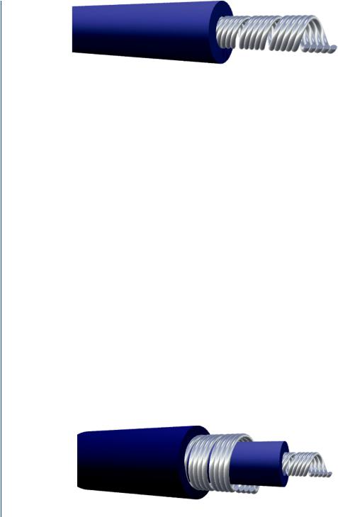
Leads can be either unipolar or bipolar. Unipolar leads, as shown in Figure 39, are single leads inside of an insulating sheath, which send the impulse signal from the pulse generator with the returning electrical signal traveling through the tissues to the pacemaker. The unipolar lead normally has a smaller diameter than the bipolar lead and exhibits a greater tendency for pacing artifacts on the surface EKG, since the returning electrical signal travels through tissue.
The bipolar lead, as shown in Figure 40, is a coaxial lead with a larger overall diameter. The returning signal (after stimulating cardiac muscle) pathway is through the second embedded lead, rather than through tissues. As a result, the bipolar lead has a lower susceptibility to affect
FIGURE 38: Steroid eluding lead designed to deter inflammatory response and fibrous capsule formation.
36 ARTIFICIAL ORGANS
FIGURE 39: Unipolar pacemaker lead.
the EKG and is less susceptible to external interference, such as from ambient electromagnetic “noise.”
The insulation on pacemaker leads is either silicone or polyurethane. Silicone is inert, biocompatible, biostable, repairable with medical adhesive, and has a long and successful history in biomedical applications. Polyurethane is also biocompatible, but additionally has a higher tear strength, lower friction coefficient, and a smaller required thickness.
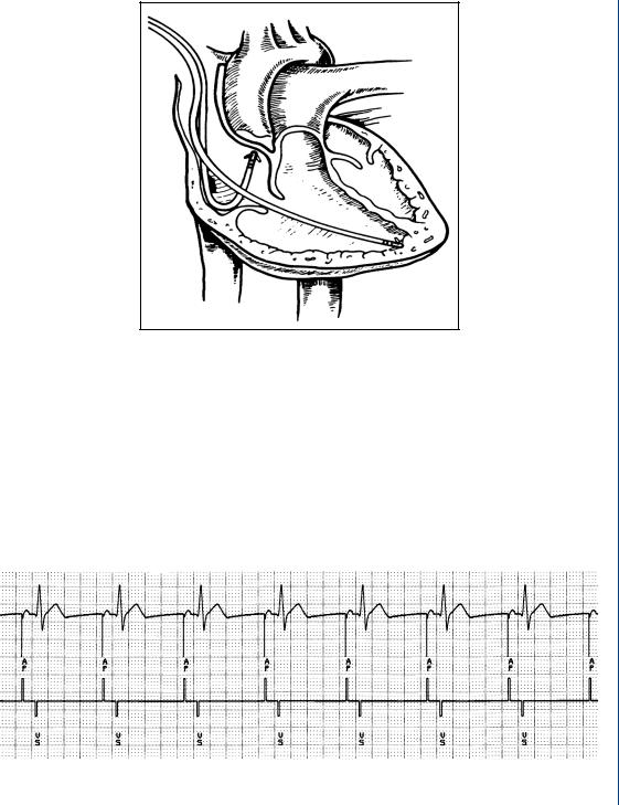
Pacemaker systems that are fixed rate often utilize a single lead that is placed in the atrium (if there is an SA nodal problem) or the ventricle for AV nodal or bundle branch problems. For circumstances where there is a need for a demand style pacemaker, there must be two leads placed within the heart as seen in Figure 41.
The sensing electrode is placed within the atrium to sense any variation in normal sinus rhythm, such as what might occur during exercise of increased heart activity. The stimulating electrode might be placed within the ventricle and the rate of stimulation is dependent on the sensed SA nodal rate. Modern demand pacemakers thus have four main functions:
•Stimulate cardiac depolarization
•Sense intrinsic cardiac function
•Respond to increased metabolic demand by providing rate responsive pacing
•Provide diagnostic information stored by the pacemaker.
The output of the pacemaker, which stimulates cardiac tissue, can be visualized on the surface EKG as is seen in Figure 42.
FIGURE 40: Bipolar pacemaker lead.
CARDIAC PACEMAKERS 37
FIGURE 41: Demand style pacemaker with two leads: one for sensing and one for stimulation.
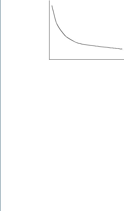
A typical stimulating pulse from the pulse generator must be large enough to cause depolarization (i.e., to “capture” the heart) and must be sufficient to provide an appropriate pacing safety margin. The pulse width must be long enough for depolarization to disperse to the surrounding tissue. As such, pulse generation waveforms are typically evaluated on a strength duration curve as noted in Figure 43.
Once a pacemaker elicits a stimulating pulse and the heart muscle depolarizes, there exists a refractory period whereby another stimulating pulse would not elicit further depolarization.
FIGURE 42: Surface EKG with pacemaker stimulation pulses noted within the EKG waveform as well as on the axis below.
38 ARTIFICIAL ORGANS
Stimulationthreshold |
Capture |
|
Pulse width (ms)
FIGURE 43: Strength–duration curve to evaluate the required necessary stimulating pulse to achieve “capture,” i.e., produce a depolarization.
This same refractory period exists during normal cardiac electrical stimulation, such that any ectopic wave would not elicit a second depolarization. Repolarization would normally need to occur before a second pulse would produce another depolarizing wavefront. As was noted above, modern pacemakers often employ a sensing electrode in one heart chamber and a second stimulating electrode in another chamber. A system of classification has been established for pacemakers which is used to describe the various parameters that can be incorporated into modern pacemakers, as seen in Figure 44.
Referring to this classification system, a VOO pacemaker (see chart) stimulates the ventricle with no atrial or ventricular sensing (nor any response to sensing). This would be a fixed rate pacemaker that stimulated the ventricle regardless of the patient’s intrinsic cardiac
CHAMBER |
CHAMBER |
RESPONSE |
PROGRAM |
|
PACED |
SENSED |
TO SENSING |
FUNCTION |
FUNCTION |
|
|
|
|
|
V: Ventricle |
V: Ventricle |
T: Triggered |
P: Simple |
P: Pace |
|
|
|
|
|
A: Atrium |
A: Atrium |
I: Inhibited |
M: Multi |
S: Shock |
|
|
|
|
|
D: Dual |
D: Dual |
D: Dual |
C: Communicating |
D: Dual |
|
|
|
|
|
O: None |
O: None |
O: None |
R: Rate modulate |
O: None |
|
|
|
|
|
S: Single |
S: Single |
O: None |
|
|
|
|
|
|
|
FIGURE 44: Pacemaker classification system.

CARDIAC PACEMAKERS 39
electrophysiology. A VVI pacemaker (see chart) senses ventricular electrical activity and paces the ventricle if there is a lack of normal intrinsic activity sensed. If normal ventricular excitatory pulses are sensed, then the pacemaker output is inhibited (the I) in the pacemaker classification. A VVIR pacemaker is identical to the VVI pacemaker except for the added “R” term indicating program function (R = rate). This pacemaker changes the stimulation rate of firing when the intrinsic ventricular stimulation warrants it. Similarly, a VAIR pacemaker senses atrial activity and stimulates the ventricles. The pacemaker pulse rate is affected by the atrial activity. If the patient’s metabolic activity alters the SA nodal firing rate, then the pacemaker senses this and increases the ventricular firing rate. If there is a normal sinus rhythm, then the pacemaker output is inhibited. Similarly, a VDIR pacemaker senses intrinsic activity in both chambers with the pacemaker capable of delivering a variable rate.
Originally, pacemakers of the 1950s were external devices with the leads implanted into the heart. The first transistorized, wearable, battery powered pacemaker developed by Wilson Greatbach in 1957, and the first totally implanted pacemaker was in 1960. The battery life was approximately 18 months. In the mid-1960s, transvenous leads were developed that could be introduced through a vein, rather than require opening the chest to attach the lead. Original designs for pacemakers incorporated a fixed rate. In the mid-1960s, the first “demand” pacemakers were developed that sensed when there was a missed beat and then initiated a pulse to excite the cardiac muscle, while being inactive during normal sinus rhythm. The screw tip and tined leads were developed in the 1970s, and in 1975, the longer lasting lithium iodide battery was developed to replace the mercury–zinc battery. At that same time, the titanium case and epoxy top was developed, which better shielded the pacemaker from outside electromagnetic disturbances, such as a microwave oven. In that same time span, the first programmable pacemakers were developed as were the first dual chamber pacemakers. In the 1990s, the pacemakers became smaller with advances in batteries and in microelectronics. To date, over 2 million cardiac pacemakers have been successfully implanted.
3.4PACEMAKER IMPLANTATION
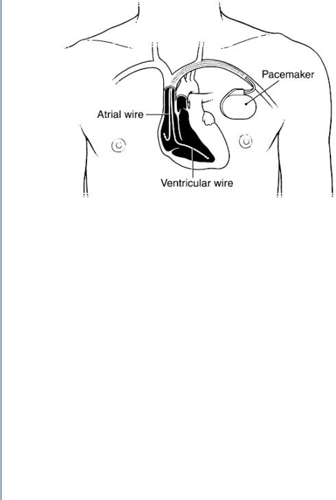
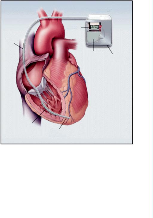
A schematic diagram depicting the surgical implantation of a cardiac pacemaker is shown in Figure 45. The pacemaker pulse generator with its epoxy top is implanted just below one of the collarbones. The leads are then inserted through a vein leading to the heart or via minimally invasive surgery to affix them to the exterior of the heart.
The use of the easily accessible site below the collarbone allows the pulse generator with its battery pack to be easily replaced once the batteries have become depleted. By using a local anesthetic, a small opening in the skin and underlying thin tissues can be created in order to remove the pulse generator. Since the leads are connected to the epoxy top of the pulse generator by means of a force fit, then the leads can be easily removed and snapped
40 ARTIFICIAL ORGANS
FIGURE 45: Implantation of a cardiac pacemaker pulse generator below a collarbone with the leads threaded through a nearby vein toward the heart.
into the replacement pulse generator (and battery pack) within the new epoxy top associated with the new generator. The time “off ” of pacing is thus extremely short—the time it takes to pull the lead(s) out of one epoxy top and into another. The new pulse generator is then placed in the site of the old unit, and the small incision is then closed. The entire replacement procedure often takes as little as 30 min from open to close. As the modern batteries for cardiac pacemakers can last as long as 12 years, replacement of the pulse generator is infrequent.
3.5CARDIOVERTER
If the patient is susceptible to ventricular fibrillation, then a standard cardiac pacemaker may not be able to reestablish sinus rhythm. As with the case when an individual suffers a “heart attack,” where VF occurs, it is necessary to convert the patient by completely depolarizing the entire heart by means of a defibrillator. Most individuals are familiar with external defibrillators that use large paddles and a large current density to provide an overwhelming depolarization to the heart. The premise is that when the heart then completely repolarizes, that the SA node will fire before any other site within the heart and reestablish sinus rhythm. The large paddles and large current density are necessary for external defibrillation, as the skin and exterior tissues provide a large resistance to electrical current flow.
CARDIAC PACEMAKERS 41
Pulse generator
Circuitry
Shock
coil
Battery
Casing
(cut away)
Shock
coil
Pacing electrodes
FIGURE 46: Dual pacemaker and cardioverter within the same case. Note the shocking coil which surrounds the pacing lead.
However, if the defibrillator were placed deeper within the body, then the amount of current necessary to defibrillate the heart is far less. As a result, the device is far smaller. For those patients who may require defibrillation on a regular enough basis, an implantable version can be placed in the same site as a cardiac pacemaker—below the collarbone with the leads threaded through a vein toward the heart. For those patients who require frequent cardiac pacing, but are also less frequently susceptible to ventricular fibrillation, then a combination unit of pacemaker and implantable cardioversion device (ICD) is implanted as shown in Figure 46. This device is sometimes called an implantable cardiac defibrillator (ICD).

42 ARTIFICIAL ORGANS
The shocking coil for the cardioverter (defibrillator) unit (within the same housing as the pacemaker) surrounds the pacemaker lead. Should the pacer sensing electrodes detect ventricular fibrillation and the normal pacing protocol does not reestablish sinus rhythm, then the cardioverter fires to completely depolarize the heart. The pacemaker portion of the housing is electrically decoupled and insulated from the cardioverter during this process so as to avoid damage to the pacemaker circuitry.
Studies regarding the development of cardiac pacemakers have been ongoing for several decades. More recent studies include a discussion of permanent transvenous pacing by Petrie (2005), a discussion regarding appropriate selection of a pacemaker by Ellenbogen and Wood (2005), a discussion regarding the use of single chamber versus dual chamber pacing by Toff et al. (2005), an update on implantable pacemakers by Woodruff and Prudente (2005), and indications and recommendations for pacemaker therapy by Gregoratos (2005).
Several studies have examined the role of interfering external factors that may adversely affect a cardiac pacemaker. Of particular note has been the effect of an MRI on pacemaker activity as reported by Irnich et al. (2005), Vahlhaus (2005), and Del Ojo et al. (2005). Other external factors recently examined regarding interference with pacemaker performance included electromagnetic fields of high voltage lines by Scholten et al. (2005), and electromagnetic interference from induction ovens by Hirose et al. (2005).
Clinical issues that may adversely affect pacemaker performance include dislodged and/or fibrosed leads as discussed by Khan et al. (2005), Shimada et al. (2002), and Cutler et al. (1997). Issues associated with the use of implantable cardioverter defibrillators were examined by Nazarian et al. (2005), Gersh (2004), Sanders et al. (2005), Alter et al. (2005), Bryant et al. (2005), and Silver (2005).
The use of implantable cardiac pacemakers has proven to be an extremely successful “artificial organ” with millions of patients successfully treated. The later use of implantable defibrillators and dual pacemaker/defibrillators has also been successful, albeit with far less cases to date than with pacemakers alone.

43
C H A P T E R 4
Dialysis
The human kidneys are responsible for continually cleansing blood of metabolic waste products (such as urea, uric acid, creatinine), excess ions, and excess water. The resultant filtrate is then transported to the ureter to be removed as urine. Approximately 20% of the blood supply is routed to the kidneys at any time in order to provide a continual means of removing potentially toxic materials from the blood. The water removal from the kidneys serves as a secondary means of controlling blood pressure, as total blood volume is a factor in venous return, cardiac output, and thus arterial pressure. There are two kidneys, each consisting of a network of millions of individual mass transfer elements called nephrons. Transport occurs across the surface of the nephron. As is the case with the lungs, which have similar elements called alveoli, the nephrons provide a means of greatly expanding the surface area available for mass transfer within a constrained volume. The theory is similar to that of a single large sphere as compared to millions of smaller spheres within the same volume. The net surface area of the large sphere is much smaller than that of the combined surface area of the numerous small spheres. Thus, mass transfer of metabolic waste products occurs by branching blood into smaller and smaller channels until the actual mass transfer occurs at the small end point—the nephron. Again, this is similar to the trachea branching into the bronchi and eventually to the alveoli in the lungs.
4.1THE NEPHRON AND MASS TRANSFER
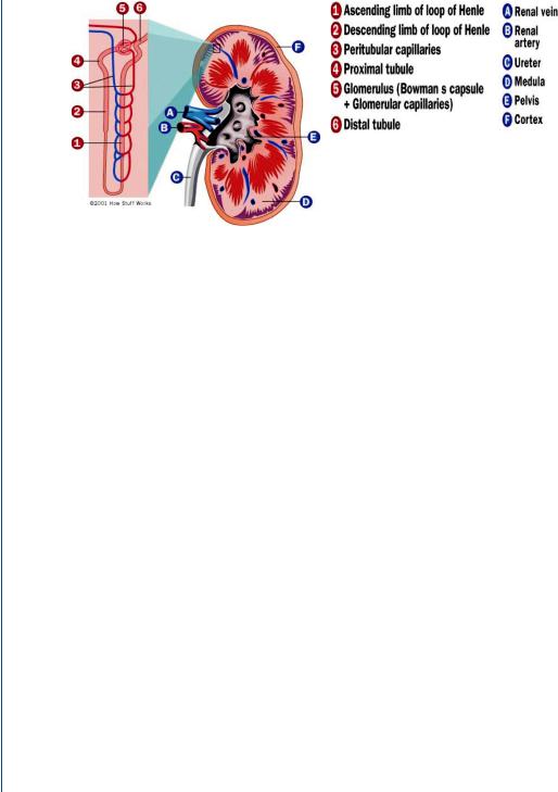
The kidney and its most elemental mass transfer unit, the nephron, are shown in Figure 47. Unlike most organs within the human body, the kidneys are supplied with blood directly from an arteriole, which branches from the renal artery. The use of an arteriole allows for control of the source hydrostatic pressure to each nephron (by means of vasoconstriction or vasodilation) and provides a constant source of pressure to each mass transfer unit.
The nephron |
consists of the glomerulus, a relatively porous membrane with pores |
˚ |
˚ |
diameters of 50A and pore lengths of 500A. These pore diameters allow a large amount of fluid
to enter into the nephron tubule system, while excluding (by size) such blood elements as cells, large proteins, large sugars, etc. The glomerular filtration rate (GFR), the amount of fluid flow through all of these membranes, equals 125–150 mL/min. As the total blood flow to the kidneys
44 ARTIFICIAL ORGANS
,
FIGURE 47: The human kidney and the nephron (shown in detail to the left).
equals 1000–1200 mL/min (20–25% of total blood flow), and plasma (the liquid portion of blood) represents approximately one half of the renal blood flow (for a hematocrit of 45% plus white cells and platelets), then the GFR represents approximately 25% of plasma renal flow (150 of 600 mL/min). This means that 25% of the liquid portion of the blood is leaving the blood as it travels into the tubules of the nephron. Luckily, only about 1–2 mL/min eventually finds its way to the ureter, which indicates that the remainder is returned to the blood supply. This occurs through reabsorption of the filtrate into blood vessels that parallel each nephron, the vasa recta or peritubular capillaries as is seen in Figure 47. The glomerular filtration rate is controlled by a hydrostatic pressure gradient as well as an osmotic pressure gradient (from the blood side to the filtrate side across the glomerulus). The hydrostatic pressure gradient is a relatively large 50 mmHg (for so short of a “pore” length) and the reverse osmotic pressure gradient is 25 mmHg. The osmotic pressure gradient is reversed from the hydrostatic pressure gradient since cells and large proteins on the blood side do not travel across the pores, and exert an osmotic pressure from the filtrate side to the blood side. The net 25 mmHg pressure gradient that pushed fluid across the glomerulus is still quite large and results in a significant transport of fluid as was described above.
The filtrate (the name of the fluid once it enters the tubules of the nephron) then follows the tubule pathway from the proximal tubule, through the loop of Henle, then through the distal tubule and the collecting duct, eventually ending in the ureter. Along the way, through a combination of concentration-driven passive diffusion as well as active transport, positive ions are transported across the tubules into the surrounding extracellular fluid. Negative ions follow the same pathway, primarily by means of a charge balance as well as passive diffusion. Water follows along the same pathway by means of a concentration-driven osmosis. All of these constituents are then absorbed by the vasa recta to return to the blood supply.