

Artificial Organs - Gerald E. Miller
.pdfARTIFICIAL HEART VALVES 5
FIGURE 5: Thrombus formation at the seat of a ball valve as a result of the closing force of the ball against its seat.
pressure available to propel blood through a circulation. This type of valve also has a large vertical profile that makes implantation, particularly in the mitral position, somewhat difficult for many patients whose anatomical space is limited.
The tilting disk valve, as seen in Figure 6, opens to 60◦ as constrained by a stainless steel strut. The disk is constructed of pyrolytic carbon, given the trade name pyrolite.
Suture ring
Occluder
disc
Inlet strut
Outlet strut
Flange
FIGURE 6: Tilting disk valve in the open position.
6 ARTIFICIAL ORGANS
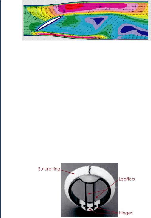
FIGURE 7: Flow patterns around a tilting disk valve generated by computational methods. Note the reversal of the velocity vector behind the tilted disk and the higher velocities at the periphery.
The tilting disk valve has an open profile that offers blood flow around the tilted disk as well as to the outer sides, which are between the disk and the blood chamber or artery. As such, it is far less of a central occluder to blood flow than the ball valve and has a smaller pressure drop across the open valve, which is also advantageous. This valve only opens to 60◦ due to the stainless steel strut assembly. The valve is not actually affixed to the struts. A flow pattern across the open valve is shown in Figure 7, which indicates a partial central occluder (the tilted disk) as well as peripheral flow around the disk. There is a bit of recirculation behind the disk and the peripheral flow is at relatively high velocities as compared to the central region. As is the case with most flow images, the red (or dark gray) colors in the image refer to higher velocities, the yellow (or lighter gray) refer to moderate velocities, the green (or lighter gray) refer to small velocities, and the blue (or very light gray) refer to extremely small (near zero) velocities. Arrows within the flow field indicate individual vector lines of fluid particles within the flow field.
Many modern prosthetic heart valves are bileaflet in nature as shown in Figure 8.
The bileaflet valves open to 80◦ and pivot via pins that connect to the valve leaflets and protrude into slots within the annular ring. The ring is composed of either stainless steel or titanium, often with a pyrolytic carbon coating. There is a dacron sewing ring attached to the
FIGURE 8: Bileaflet valve showing flanges where leaflet pins pivot within annular ring.
ARTIFICIAL HEART VALVES 7
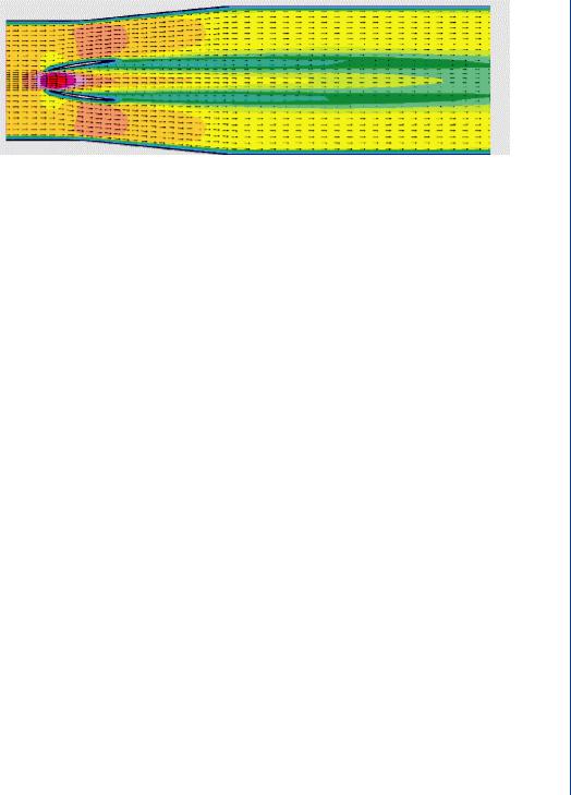
FIGURE 9: Flow through an open bileaflet valve with a large central flow region as well as a large peripheral flow region. Trailing edge vortices are seen emanating from the tips of the leaflet edges.
metal substrate for ease in attachment to the valve orifice. The leaflets are often composed of pyrolytic carbon for strength and durability. With two leaflets, the closing force is less than that of a single tilting disk valve, and certainly far less than that of a ball valve. As the pin assembly can be a site for thrombus formation, such valves normally have a washout zone near the pins to flush that area and avoid stagnant blood leading to thrombus formation. As such, this valve has mild regurgitation as a design element. Figure 9 depicts flow across an open bileaflet valve, indicating far more central flow than the tilting (monoleaflet) valve. There is no central occluder in the bileaflet valve as there was (partially) with the tilting (monoleaflet valve). Thus, there is a greater central flow region in this type of valve.
Ideally, prosthetic heart valves require low levels of hemolysis (red cell destruction), low levels of thrombosis, and a long life span (20–30 years). Most patients must receive anticoagulants indefinitely to deter thrombosis. Pyrolytic carbon and silicon rubber as valve or ball materials have been shown to be relatively antithrombogenic and their surfaces are often covered with proteins over time. Dacron polyester is sometimes used for valve leaflets. Such a material is more flexible than the pyrolite leaflets and thus closes with far less force and less hemolysis. However, such flexible leaflets also take longer to open and close, as they flex during the leaflet movement. An undue delay in valve closure produces a slight backflow, not unlike that of a natural human valve, which produces the incisura (dip) in the aortic pressure waveform. However, too much delay can adversely affect net forward flow, thus reducing net cardiac output.
Bioprosthetic valves, often a preferred alternative, are composed of natural valves from a pig, which has a cardiovascular system most similar to humans. These valves must be “treated” with glutaraldehyde to resist antigenicity or rejection of a foreign substance. As such, these biological valves are stiffer than natural heart valves due to the treatment process. In some cases, the bioprosthetic valve has a dacron sewing ring attached along its base and may even have a stiffening ring of stainless steel attached along its base as well. In some cases, dacron is attached along the outer face of the leaflets to provide greater strength to the leaflets. This does not
8 ARTIFICIAL ORGANS
Natural heart tissue
Polymer scaffold
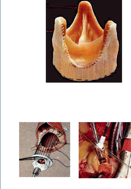
FIGURE 10: Bioprosthetic (pig) valve with dacron along the base and outer edges of the leaflets.
significantly add to the stiffness of the leaflets as compared to the glutaraldehyde treatment. Figure 10 depicts a bioprosthetic valve with a dacron covering.
Surgical implantation of prosthetic heart valves has evolved into an efficient and rapid procedure. The orifice diameter of the patient is evaluated with the aid of pulse echo ultrasound,
FIGURE 11: Prosthetic heart valve within valve holder with sutures preplaced within sewing ring and valve orifice.

ARTIFICIAL HEART VALVES 9
the 2-D version often called echocardiography. The appropriately sized prosthetic valve is then placed into a valve holder and sutures are threaded through the sewing ring of the valve. The patient is placed on cardiopulmonary bypass (heart–lung machine) and the original valve is removed. The prosthetic valve is then placed into the orifice by one surgeon and another continually sews the sutures around the valve orifice using the curved needle attached to the sutures. The valve holder is then lowered into place, and the holder eventually depressed to release the valve—and the empty holder is then removed. The orifice is checked for potential leaks and additional sutures are placed on site as needed. The patient is then removed from bypass and the incision site closed as is the chest incision. The entire procedure often is completed within 1 h and the patient is normally on cardiopulmonary bypass for as little as 15 min. Figure 11 depicts a prosthetic heart valve within a valve holder with sutures in place.
1.3EVALUATION OF PROSTHETIC VALVES
The performance and efficacy of prosthetic heart valves are normally evaluated by means of pressure gradients across the open valve, long-term durability, and prevalence of adverse physiological conditions such as calcification, stenosis, thrombosis, or hemolysis. Pressure gradients can be determined via direct pressure sensors or via Doppler ultrasound (indirect determination by means of flow/pressure relationship). Thrombosis, hemolysis, and calcification are determined via direct biochemical measures or via imaging modalities such as ultrasound. Such determinations are on mechanical test beds or blood flow loops in mock circulatory systems, or with animal models. Computer modeling techniques are also employed to evaluate valve performance using computational fluid dynamics. An excellent review of the fluid mechanics of prosthetic heart valves was produced by Yoganathan et al. (2004). Other groups involved with the evaluation of prosthetic and bioprosthetic heart valves include Labrosse et al. (2005), Jamieson et al. (2005), Medart et al. (2005), Pierrakos et al. (2004), Malouf et al. (2005), Goetze et al. (2004), Wu C et al. (2004), and Wu Y et al. (2004).

11
C H A P T E R 2
Artificial Heart and Cardiac
Assist Devices
2.1CARDIAC ANATOMY AND PATHOPHYSIOLOGY
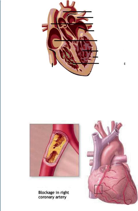
As was described above in the section dealing with heart valves, the human heart consists of two ventricles responsible for ejection of blood and two atria responsible for holding and filling the ventricles. The left heart pumps blood into the systemic circulation and the right heart into the pulmonary circulation. Figure 12 depicts the heart with all four chambers.
According to the National Center for Chronic Disease Prevention, 950 000 Americans die each year due to cardiovascular disease with over 61 million Americans suffering from this disease and over 6 million hospitalizations each year as a result. Major causes of cardiac-related pathologies include atherosclerosis in either the aorta or in coronary vessels such as depicted in Figure 13.
In many cases, coronary artery blockages and/or blockages in the aorta can be alleviated via surgery to remove the blockage, either through mechanical “reaming,” via laser ablation, or via balloon catheter expansion. Often, stents are placed in a coronary vessel after removal of the blockage. In those instances where the blockage cannot be removed by such means, more extensive surgery can be performed to bypass the blockage with transplanted veins or via artificial vessels composed of biomedical polymers. This procedure is termed coronary artery bypass grafts or CABGs.
Often after such surgery, the patient’s repaired heart is too weak to fully support the blood pumping requirements of the systemic circulation and will require some period of reduced load in order to recover. In other cases, the repaired heart cannot ever function at a normal level of 5 L/min at 95% oxygen saturation with a mean pressure of 100 mmHg. In still other cases, the heart cannot be adequately repaired and functions at a reduced level on a permanent basis. One approach to the latter cases would be to seek a heart transplant. However, given the vast number of potential cases in need of such a transplant and the inherent need for appropriate blood typing and tissue typing, there are insufficient numbers of donor hearts. The United Network for Organ Sharing notes that donor hearts number 2000–3000 per year with the stated need at least tenfold greater.
12 ARTIFICIAL ORGANS
Aorta
Pulmonary
Artery
Superior
Vena cava
Left atrium
Right atrium
Left ventricle
Heart muscle Right ventricle
Inferior vena cava
FIGURE 12: The human heart with four chambers: two atria and two ventricles.
As such, a stopgap mechanism is to employ a mechanical assist pumping system, called a ventricular assist device or VAD. This can be utilized in true “assist” mode for those patients recovering from open heart surgery and whose heart will recover full function within a few days. In those other cases where the patient’s heart will not completely recover, or where surgical
FIGURE 13: Coronary artery blockage with inset showing blockage and larger view showing location within the heart musculature.

ARTIFICIAL HEART AND CARDIAC ASSIST DEVICES 13
intervention would not be beneficial, then this device can be utilized for a longer period until such time as a donor matching heart becomes available. In such cases, the device is termed as a “bridge to transplant.” In the first two cases, the natural heart might pump as little as 2–3 L/min with the artificial heart pumping the remainder. When the left heart is being assisted, the device is termed an LVAD (left ventricular assist device). When the right heart is to be assisted, the device is termed an RVAD. For those cases where both hearts are being assisted, two devices are used in biventricular assist mode (BiVAD). In still other cases, when the patient’s own heart cannot function even partially at the above level, it may be necessary to completely replace the failing heart with two pumps acting in tandem as a total artificial heart for end-stage heart failure.
2.2HEART ASSIST TECHNOLOGY
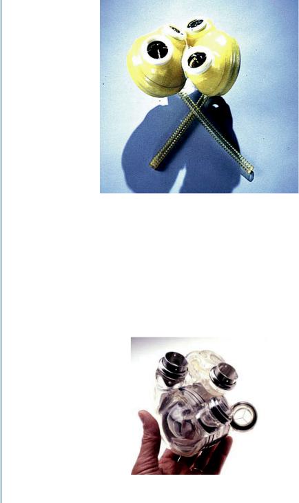
Artificial hearts and heart assist devices have been in development and analysis for decades. The original pneumatically powered design, as typified by the Jarvik-3 and the Jarvik-7 pumps, consisted of a polycarbonate case surrounding a flexible polyurethane sac. The space between the two allowed high pressure air, designated as “systolic drive pressure” to collapse the blood containing sac and caused systolic ejection. A small vacuum pressure, designated as “diastolic pressure” pulled the sac toward the casing and caused diastolic filling. Artificial heart valves were employed for each artificial ventricle to prevent backflow during either portion of the cardiac cycle in a fashion similar to the natural heart. This sac type pump acted in a fashion similar to the natural heart in that it was inflow and inlet pressure sensitive (designated as preload sensitive), but not affected by the load against which the heart pumps (designated as not being afterload sensitive). The Jarvik pump is shown in Figure 14, with the air lines from the outer casing which are then connected to a drive system that provides the alternating high and low pressure to the blood sac. The two pressures, the systolic duration, and beat frequency can all be controlled and varied from a drive console.
Although pneumatically driven pumps are still utilized clinically, many original such designs have now incorporated electrically powered cam drive systems that move a piston/diaphragm arrangement to eject blood during systole and then, when the piston is pulled back toward the drive unit, initiates diastolic filling. Such blood pumps are still pulsatile and thus need valves to eliminate backflow and regurgitation. A biventricular device of this type is shown in Figure 15, with no pneumatic air lines emanating from the pump as was the case for the sac-type design.
Power for the electrically operated LVADs or BiVADs is achieved with external, rechargeable batteries as is shown in Figure 16. Transcutaneous energy transmission occurs via a pair of coils—one placed over the skin and one placed below the skin, the latter attached to the VAD. The VAD is connected to the apex (base) of the left ventricle (or to the base of both ventricles in biventricular support) with the aid of an inlet cannula. This orientation allows gravity to
14 ARTIFICIAL ORGANS
FIGURE 14: The Jarvik-7 pneumatically driven artificial heart showing two ventricles and the air lines which lead to the spacing between the outer casing and the inner flexible blood sac.
assist emptying of the ventricle into the device, which offloads the ventricle in part. The VAD then pumps a portion of the cardiac output through a cannula that connects to the aorta via an end-to-side anastomosis.
Unlike the pneumatically driven blood pumps, where the air from the pneumatic drive unit is vented to the atmosphere, the electrically driven pumps are normally closed systems.
FIGURE 15: Biventricular electrically operated pusher plate design for a blood pump with four valves similar to that of the natural heart.