

Artificial Organs - Gerald E. Miller
.pdfARTIFICIAL HEART AND CARDIAC ASSIST DEVICES 15
FIGURE 16: Novacor electrically powered LVAD with external battery pack and connecting cannula from apex of left ventricle and to aorta.
As such, when the diaphragm moves back toward the internal drive system, there can be a period where the air within the drive chamber is compressed, resulting in an increase in local pressure. As the diaphragm moves away from the drive unit (during systole), the air in this chamber becomes rarified and the pressure is reduced. Rather than exist with changing pressures within the drive system, early versions of electrically powered pumps contained a flexible sac, a compliance chamber, whereby the excess air in the drive system is shunted to the compliance chamber, thus maintaining a relatively constant pressure within the pump drive chamber. As the diaphragm moves forward during systole, the air is shunted from the compliance chamber into the drive chamber of the pump and vice versa during diastole. Later versions of electrically operated pumps utilize a venting system to avoid the need for a compliance chamber, which is an added component that takes up space and adds to the complications of the device operation.
The use of positive displacement pumps, such as the sac or pusher plate blood pumps, offers several advantages. These include the use of pulsatile flow similar to that of the natural heart as well as an insensitivity to afterload—i.e., the device can pump against any reasonable load, even a hypertensive load. Issues with such pumps include the sensitivity to preload and
16 ARTIFICIAL ORGANS
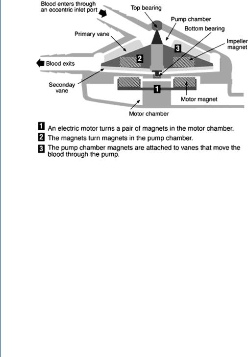
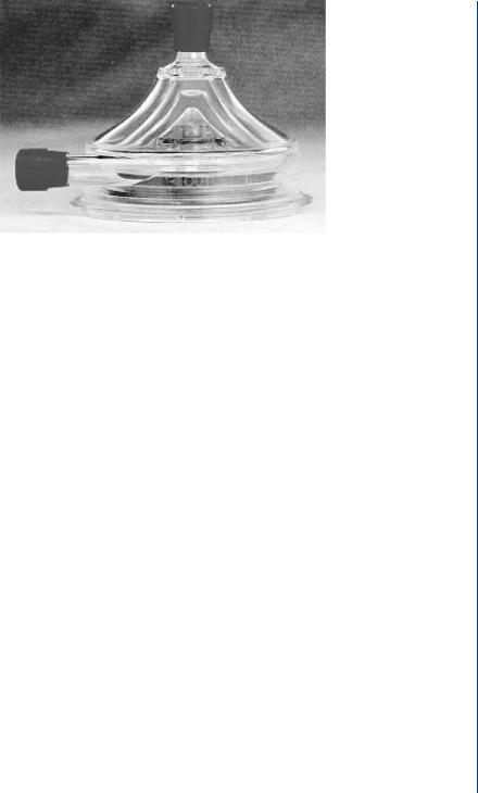
FIGURE 17: Centrifugal blood pump with inlet at top center and outlet at bottom left. Spinning rotor produces increased pressure at the periphery.
problems associated with artificial heart valves such as calcification, hemolysis, thrombosis, and mechanical failure. It was these issues that initiated the later use of rotary blood pumps as assist and/or bridge to transplant devices. Such rotary devices often require less power than their positive displacement counterparts and do not utilize valves, as they produce steady flow. Such rotary blood pumps are configured as either a centrifugal pump or as an axial pump.
The centrifugal blood pump is configured with an inlet to the pump from the top center and an outlet radially at the periphery. This arrangement is not unlike a tornado in flow design and the flow of such a device is similar—low pressure and velocity in the center with higher pressure and velocity at the periphery. Centrifugal pumps are electrically powered and utilize magnets to spin the rotor and, oftentimes, suspend the drive assembly as seen in Figure 17.
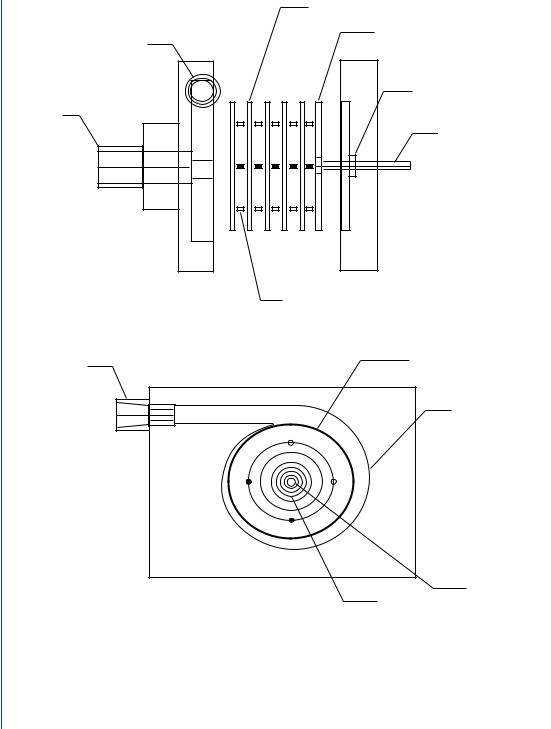
Another centrifugal design was produced by Medtronic and consists of nested cones as seen in Figure 18. Still another centrifugal design consists of a series of parallel disks spinning about an axis in unison as seen in Figure 19.
Centrifugal blood pumps have several advantages including a lack of valve-related problems, a relatively lower power drain (than positive displacement pumps), and an ability to pump at higher rates by spinning the rotor faster. Without a displacing drive chamber, there is no need
ARTIFICIAL HEART AND CARDIAC ASSIST DEVICES 17
FIGURE 18: Medtronic BP-80 centrifugal blood pump with nested cones and magnetic drive.
for a compliance chamber as there is for some positive displacement pumps. The centrifugal pumps are placed below the left ventricle in a fashion similar to the positive displacement pumps with the outlet cannula extending toward the aorta as is the case for the pulsatile pump connections. Centrifugal pumps are sized similar to their pulsatile analogs and usually can produce 5–7 L/min with an increase in pressure of 100 mmHg at rotation rates of 1500–3000 rpms. Drawbacks to such pumping systems include the use of steady flow rather than pulsatile flow, as well as being significantly affected by afterload. In fact, it is possible for such pumps to spin, but produce no forward flow, if the outlet pressure generated by the pump is lower than the afterload pressure. This is known as “deadheading” and can be remedied by spinning the rotor faster to increase the outlet pressure of the pump.
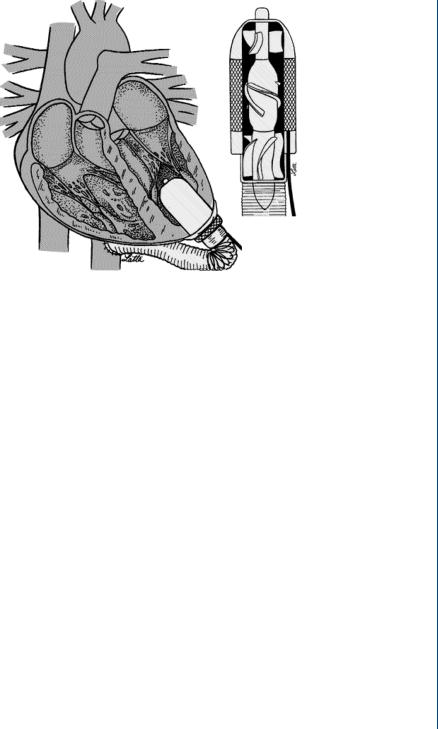
The other versions of rotary pumps are the smaller axial flow pumps. Unlike the centrifugal pumps, the axial flow pumps have their inlet forward and their outlet directly behind, much as a jet engine is configured. One advantage of such an arrangement is that the flow is more stable in the flow-through arrangement. In addition, the axial pumps, being smaller than their centrifugal counterparts, can be fitted within the base of the ventricle, thus eliminating the inlet cannula. This type of pump can also be placed within the aorta to allow for flow through the device from the left ventricle, and on toward the remainder of the systemic circulation with an added pressure and flow generated from the pump. As such pumps are smaller and have lesser blood contacting area, they require higher rotation rates than their centrifugal counterparts—often reaching 15 000–25 000 rpms. It was originally thought that such rotation rates would produce harmful shearing stresses to blood elements. However, the extremely short exposure time of blood within the device allows only partial deformation of blood elements without permanent damage occurring. A typical axial flow pump is shown in Figure 20.
18 ARTIFICIAL ORGANS
Washer-shaped disk
Solid disk
Outlet
Shaft seal
Inlet
Drive shaft
Spacer
Disk assembly
Outlet
Spiral volute
Drive shaft
Inlet
FIGURE 19: Multiple disk centrifugal blood pump based upon the Tesla Turbine design.
The axial flow pump is not only magnetically driven, but requires magnetic suspension. The rotor is magnetically suspended inside the stator, often with blood immersed bearings. A front and rear diffuser are utilized to direct blood flow toward the space between the rotor and the stator. As with their centrifugal pump counterparts, axial flow pumps are preload
ARTIFICIAL HEART AND CARDIAC ASSIST DEVICES 19
FIGURE 20: Axial flow blood pump configured within the base of the left ventricle. Flow through the device is completely axial with forward and rear diffusers to direct flow to the outer sections between the rotor and the stator.
insensitive and afterload sensitive. As such, they are relatively unaffected by inlet conditions. Axial flow pumps, being smaller in size, do not normally produce flow rates as large as centrifugal pumps, and are not normally utilized for long-term bridge-to-transplant support. However, being of a more compact size, it is far easier to configure such pumps than the larger centrifugal versions.
2.3EVALUATION OF BLOOD PUMPS
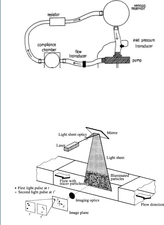
Blood pumps are usually evaluated either experimentally on the bench (designated in vitro) or in animal models (in vivo) or in clinical studies (in situ). There are also computational models using finite element techniques, collectively termed “computational fluid dynamics.” Experimental studies in vitro (on the bench) employ a mock circulatory system that mimics the human circulation in terms of the physical load against which the device must pump blood. In the bench top study, a blood analog is often employed consisting of a glycerin–water mixture. A mock circulatory system is shown in Figure 21 and consists of a compliance element simulating aortic compliance, a resistor simulating peripheral resistance, and a venous reservoir or compliance element simulating either venous inlet pressure or venous compliance.
Experimental studies of the fluid mechanics within blood pumps and inside the attached cannula (both input and output cannulae) can be typically conducted by laser Doppler anemometry (LDA) and/or particle image velocimetry. Both techniques require that the test fluid is transparent and that the associated flow field is within a transparent section. Collectively,
20 ARTIFICIAL ORGANS
FIGURE 21: Mock circulatory system for in vitro testing of blood pumps.
this field is known as flow visualization. A particle image velocimetry (PIV) system requires the use of neutrally buoyant particles that are fluorescent so as to be easily illuminated by a dual laser system. A PIV system employs a CCD camera and dual lasers to illuminate the particles at two time intervals closely spaced (within 30 ms) with the tracks between particles calculated by the supporting computer. A typical PIV system is shown in Figure 22.
FIGURE 22: Typical PIV system with laser-illuminated particles within the flow field.
ARTIFICIAL HEART AND CARDIAC ASSIST DEVICES 21
|
45 |
|
|
|
(mm) |
40 |
|
|
|
35 |
|
|
|
|
Y |
|
|
|
|
|
|
|
|
|
|
30 |
|
|
|
|
10 |
20 |
30 |
40 |
X (mm)
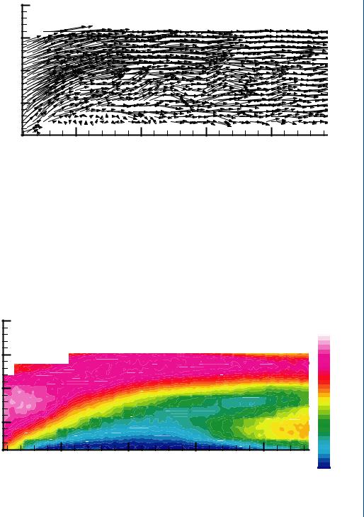
FIGURE 23: PIV vector mapping (snapshot) of particles within a flow field at one instance in time (over a 30-ms interval).
A snapshot of the fluid dynamics of the flow field generated by PIV-illuminated particles is shown in Figure 23. Such snapshots are generated 30 or more times per second and 100 of such images can be averaged to produce a flow profile indicating overall flow trends. Such an average flow profile is shown in Figure 24.
In addition to flow visualization techniques, such as LDA or PIV, it is common to measure volume flow rate with either a Doppler ultrasound flow sensor or an electromagnetic
|
45 |
|
|
|
Speed |
|
|
|
|
|
|
|
|
|
|
|
0.37 |
|
|
|
|
|
0.35 |
|
40 |
|
|
|
0.32 |
(mm) |
35 |
|
|
|
0.30 |
|
|
|
0.22 |
||
|
|
|
|
|
0.27 |
|
|
|
|
|
0.25 |
Y |
|
|
|
|
0.20 |
|
|
|
|
|
0.17 |
|
30 |
|
|
|
0.15 |
|
|
|
|
0.12 |
|
|
|
|
|
|
0.10 |
|
|
|
|
|
0.07 |
|
10 |
20 |
30 |
40 |
0.05 |
|
0.02 |
||||
|
|
|
X (mm) |
|
0.00 |
FIGURE 24: Time averaged (contour) plots from sequential vector plots of a PIV-measured flow field. Blue zone indicates low velocity (near lower wall) and red zone indicates higher velocity at outer (top) wall. Slight reversal of flow in yellow is seen at the far right.
22 ARTIFICIAL ORGANS
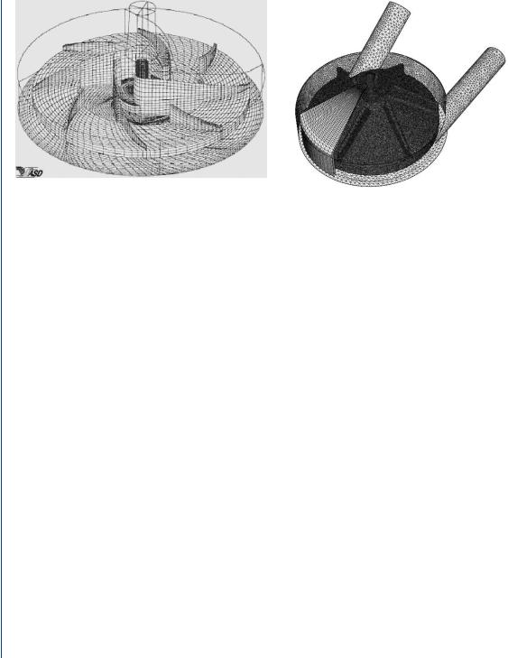
FIGURE 25: Grids generated by computational fluid mechanics algorithms to represent flow boundaries and computational accuracy steps.
flow sensor. It is also common to measure pressure within the flow field at several locations including at the inlet to the pump, at the outlet to the pump, within the compliance chamber of the mock circulatory system, and within the pumping chamber itself. Standard dome-type pressure transducers or solid-state transducers are employed. The former are less expensive, but have a limited frequency response of 100 Hz while the latter are more sensitive and accurate, can be mounted flush within a flow field conduit, but are also far more expensive and fragile.
In many cases, it may be appropriate to model the flow field by computational methods, particularly when a variety of configurations must be examined. The use of computational fluid mechanics (CFD) is often advantageous as a means of verifying experimental data as well as a method of avoiding the need to make expensive in vitro experiments with numerous physical configurations. Computational modeling employs the development of digital grids that depict the physical boundaries of the flow field within which the pressure–flow relationships can be analyzed. A typical grid pattern generated within a centrifugal pump is shown in Figure 25.
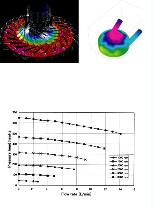
CFD algorithms can then generate simulated flow field information consisting of pressure and/or velocity fields within the physical grid framework as seen in Figure 26. It is possible to superimpose PIV or other flow visualization techniques onto the grid system as well.
Blood pumps are also evaluated in terms of pressure flow relations as well as for the potential for hemolysis. A typical pressure–flow relationship for a centrifugal LVAD is shown in Figure 27, which indicates a family of curves for various rpms of the pump. The data indicate that the flow is reduced at increasing afterload pressures, which is typical of centrifugal pumps. Similar performance curves of pressure versus flow are typically utilized for all LVAD designs including positive displacement pumps. Alterations in design of the pumps are often based upon the performance results noted in this figure. Hemolysis data is shown in Figure 28 and
ARTIFICIAL HEART AND CARDIAC ASSIST DEVICES 23
FIGURE 26: CFD-generated flow fields within designated grid system. Left figure indicates flow field data within the device while right figure indicates stress data on walls of the device.
is generated with the pump attached to a modified mock circulatory system with whole blood used within the circulation. Hemolysis can be evaluated as either measured evidence of plasma free hemoglobin or by an index of hemolysis which is based in part on a relative scale of plasma free hemoglobin.
FIGURE 27: Performance curves for a centrifugal blood pump indicating pressure–flow relationships for varying pump rpms. Flow is reduced at increasing pressures (afterloads).

24 ARTIFICIAL ORGANS
free hemoglobin |
(mg/dL) |
Plasma |
|
50
** P < 0.01
40
30
20 **
10
0
Pre |
1 |
10 |
10 |
30 |
40 |
50 |
60 |
70 |
Postoperative days
FIGURE 28: Hemolysis data for an LVAD showing levels of plasma free hemoglobin postoperative (postimplantation of pump). After an initial spike, the hemolysis data is quite low, which is typical of many LVAD designs.
Studies of the efficacies of various VAD technologies have been conducted by numerous investigators over the previous 50 years. Of late, several investigators have analyzed the role of ventricular assist devices as either a bridge to transplantation or as a long-term destination therapy including Mehra (2004), Birks et al. (2004), Westaby (2004), Kherani et al. (2004), Stevenson and Rose (2003), Matsuda and Matsumiya (2003), and Wheeldon (2003), among others. Additionally, there have been significant developments in the use of ventricular assist technology for use in pediatric applications as noted by Reinhartz et al. (2002), Duncan (2002), Deiwick et al. (2005), and Throckmorton et al. (2002). Biventricular support by means of mechanical devices has been studied by Samuels (2004).
The role of steady flow as generated by centrifugal and axial flow blood pumps has been debated for many years. Saito (2004), Mesana (2004), Myers et al. (2003), Ichikawa and Nose (2002), among others have examined this issue.
The status of using ventricular and circulatory assist devices was examined by a working group of the National, Heart, Lung, and Blood Institute as reported by Reinlib et al. (2003). The United Network for Organ Sharing (UNOS) has examined issues related to the use of ventricular assist technology as it pertains to the selection of patients for heart transplants. Does the use of the VAD lessen the patient’s urgent need for a transplant, thus lowering their status “in line” while waiting for a transplant? Or does it increase their needs? Morgan et al. (2004) report on the latest findings from UNOS on that topic. Deng and Naka (2002) provide an overview of the state of the art for mechanical circulatory support as do Nemeh and Smedira (2003).