


AFCS Status Box
Flight director roll modes are shown on the left and pitch on the right. Armed modes are annunciated in white and active in green. Autopilot status is displayed in the center of the AFCS Status Box.
6.3FLIGHT DIRECTOR MODES
Flight director modes are normally selected independently for the pitch and roll axes. Unless otherwise specified, all mode keys are alternate action (i.e., press on, press off). In the absence of specific mode selection, the flight director reverts to the default pitch and/or roll mode(s).
Armed modes are annunciated in white and active in green in the AFCS Status Box. Under normal operation, when the control for the active flight director mode is pressed, the flight director reverts to the default mode(s) fortheaxis(es). Automatictransitionfromarmedtoactive mode is indicated by the white armed mode annunciation moving to the green active mode field and flashing for ten seconds.
A flashing yellow mode annunciation and annunciator light indicate loss of sensor (AHRS, ADC, IAU) or navigation data (VOR, LOC, GPS, VNAV, WAAS) required to compute commands. When such a loss occurs, the system automatically begins to roll the wings level or maintain the pitch angle, depending on the affected axis. The flashing annunciation stops when the affected mode key is pressed or another mode for the axis is selected. If after ten seconds no action is taken, the flashing annunciation stops and the flight director enters the default mode for the affected axis.
Figure 6-4 Loss of VOR Signal
If the information required to compute a flight director mode becomes invalid or unavailable, the flight director
SECTION 6 – AUTOMATIC
FLIGHT CONTROL
automatically reverts to the default mode for that axis. The flight director is automatically disabled if the attitude informationrequiredtocomputethedefaultflightdirector modes becomes invalid or unavailable.
Pitch Modes
•Pitch Hold (default mode)— Holds the current aircraftpitchattitude;maybeusedtoclimb/descend to the Selected Altitude
•Selected Altitude Capture — Captures the Selected Altitude
•Altitude Hold — Holds the current Altitude Reference
•Vertical Speed — Maintains the current aircraft verticalspeed;maybeusedtoclimb/descendtothe Selected Altitude
•Flight Level Change — Maintains the current aircraft airspeed while the aircraft is climbing/ descending to the Selected Altitude
•Vertical Path Tracking — Follows an active vertical profile for enroute and terminal phases of flight
•VNAV Target Altitude Capture — Captures the VNAV Target Altitude
•Glidepath — Intercepts and tracks the WAAS glidepathonapproach(onlyavailableininstallations with GIA 63W Integrated Avionics Units and when WAAS is available)
•Glideslope — Intercepts and tracks the ILS glideslope on approach
•Go Around — Automatically disengages the autopilotandcommandsaconstantpitchangleand wings level while in the air
190-00384-07 Rev.A |
Garmin G1000 Cockpit Reference Guide for the Cessna Nav III |
6-3 |

SECTION 6 – AUTOMATIC
FLIGHT CONTROL
Table6-1liststhepitchmodeswiththeircorresponding controls and annunciations. The mode reference (shown with default measurement units) is displayed next to the active mode annunciation for Altitude Hold, Vertical Speed, and Flight Level Change modes. The NOSE UP/ NOSE DN Keys can be used to change the pitch mode reference while operating under Pitch Hold, Vertical Speed, or Flight Level Change Mode.
|
|
|
|
|
Reference |
|
Pitch Mode |
Control |
Annunciation |
Reference Range |
Change |
||
|
|
|
|
|
Increment |
|
|
|
|
|
|
|
|
Pitch Hold |
(default) |
|
PIT |
-20° to +15° |
0.5° |
|
|
|
|
|
|
|
|
Selected Altitude Capture |
* |
|
ALTS |
|
|
|
|
|
|
|
|
|
|
Altitude Hold |
ALT Key |
ALT |
nnnnn FT |
|
|
|
Vertical Speed |
VS Key |
VS |
nnnn FPM |
-3000 to +1500 fpm |
100 fpm |
|
Flight Level Change, IAS |
FLC Key |
FLC |
nnn KT |
70 to 165 kt |
1 kt |
|
Hold |
||||||
|
|
|
|
|
||
|
|
|
|
|
|
|
Vertical Path Tracking |
VNV Key |
|
VPTH |
|
|
|
|
|
|
|
|
|
|
VNAV Target Altitude |
** |
|
ALTV |
|
|
|
Capture |
|
|
|
|||
|
|
|
|
|
||
Glidepath |
APR Key |
|
GP |
|
|
|
Glideslope |
|
GS |
|
|
||
|
|
|
|
|||
Go Around (in air) |
GA Switch |
|
GA |
|
|
|
|
|
|
|
|
|
|
*ALTS is armed automatically when PIT, VS, FLC, or GA is active, and under VPTH when the Selected Altitude is to be captured instead of the VNAV Target Altitude.
**ALTV is armed automatically under VPTH when the VNAV Target Altitude is to be captured instead of the Selected Altitude.
Table 6-1 Flight Director Pitch Modes
6-4 |
Garmin G1000 Cockpit Reference Guide for the Cessna Nav III |
190-00384-07 Rev.A |
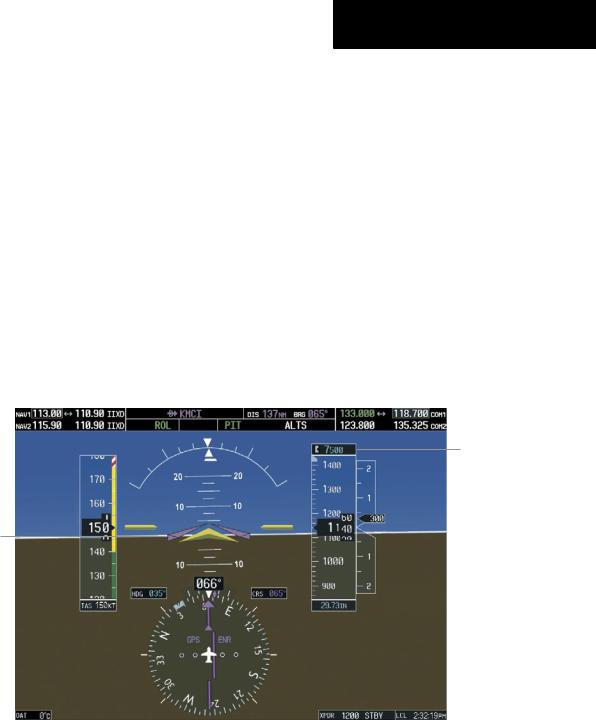
Pitch Hold Mode (PIT)
When the flight director is activated (the FD Key is pressed), Pitch Hold Mode is selected by default. Pitch Hold Mode is indicated as the active pitch mode by the green annunciation ‘PIT’. This mode may be used for climb or descent to the Selected Altitude (shown above the Altimeter), since Selected Altitude Capture Mode is automatically armed when the mode is activated.
In Pitch Hold Mode, the flight director maintains a constant pitch attitude, the pitch reference. The pitch reference is set to the aircraft attitude at the moment of mode selection. If the aircraft pitch attitude exceeds the flight director pitch command limitations, the flight director commands a pitch angle equal to the nose-up/ down limit.
SECTION 6 – AUTOMATIC
FLIGHT CONTROL
Changing the Pitch Reference
When operating in Pitch Hold Mode, the pitch reference can be adjusted by:
•Using the NOSE UP/NOSE DN Keys
•Pressing the CWS Button, hand-flying the aircraft to establish a new pitch reference, then releasing the CWS Button
Pitch Hold Mode Active |
Selected Altitude Capture |
|||
Mode Armed |
||||
|
|
|||
|
|
|
|
|
Selected
Altitude
Command Bars Main-
tain Desired Pitch
Reference
Figure 6-5 Pitch Hold Mode
190-00384-07 Rev.A |
Garmin G1000 Cockpit Reference Guide for the Cessna Nav III |
6-5 |
SECTION 6 – AUTOMATIC
FLIGHT CONTROL
Selected Altitude Capture Mode (ALTS)
Selected Altitude Capture Mode arms automatically when the flight director is in Pitch Hold, Vertical Speed, Flight Level Change, or Go Around Mode. This mode is also armed automatically under Vertical Path Tracking Mode when the Selected Altitude is to be captured instead of the VNAV Target Altitude. The white ‘ALTS’ annunciation indicates Selected Altitude Capture Mode is armed (see Figure 6-5 for example).
The ALT Knob is used to set the Selected Altitude, shownabovetheAltimeteruntilSelectedAltitudeCapture Mode becomes active.
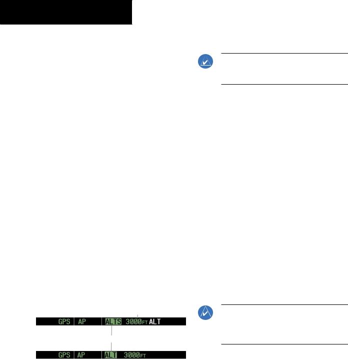
As the aircraft nears the Selected Altitude, the flight director automatically transitions to Selected Altitude Capture Mode with Altitude Hold Mode armed (Figure 6-7). This automatic transition is indicated by the green ‘ALTS’ annunciation flashing for up to ten seconds and the appearance of the white ‘ALT’ annunciation. The Selected Altitude is shown as the Altitude Reference beside the ‘ALTS’ annunciation.
At 50 ft from the Selected Altitude, the flight director automatically transitions from Selected Altitude Capture to Altitude Hold Mode and holds the Selected Altitude (shownastheAltitudeReference). AsAltitudeHoldMode becomesactive,thewhite‘ALT’annunciationmovestothe active pitch mode field and flashes green for ten seconds to indicate the automatic transition.
Altitude Reference (In
This Case, Equal to
Selected Altitude)
Flash Up to 10 sec, Indicating Automatic Transition
Figure 6-6 Automatic Mode Transitions During Altitude Capture
Changing the Selected Altitude
NOTE:PressingtheCWS ButtonwhileinSelected Altitude Capture Mode does not cancel the mode.
Use of the ALT Knob to change the Selected Altitude while Selected Altitude Capture Mode is active causes the flight director to revert to Pitch Hold Mode with Selected Altitude Capture Mode armed for the new Selected Altitude.
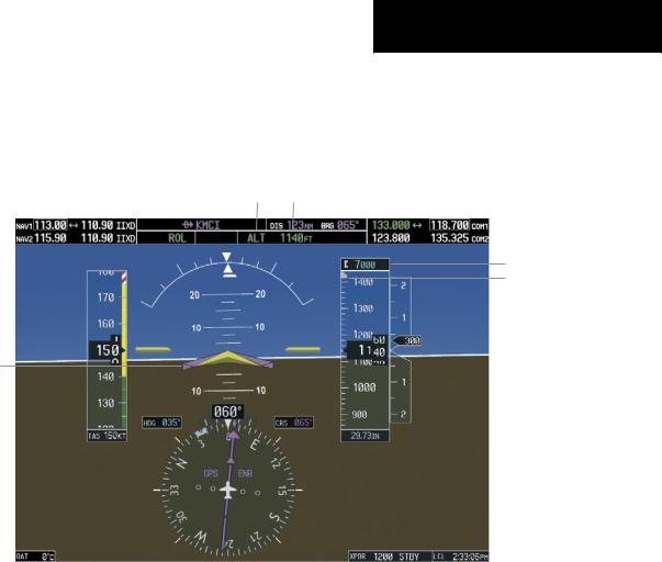
Altitude Hold Mode (ALT)
Altitude Hold Mode can be activated by pressing the ALT Key; the flight director maintains the current aircraft altitude (to the nearest ten feet) as the Altitude Reference. The flight director’s Altitude Reference is shown in the AFCS Status Box and is independent of the Selected Altitude, displayed above the Altimeter. Altitude Hold Mode active is indicated by a green ‘ALT’ annunciation in the AFCS Status Box.
Altitude Hold Mode is automatically armed when the flight director is in Selected Altitude Capture Mode. Selected Altitude Capture Mode automatically transitions to Altitude Hold Mode when the altitude error is less than 50 ft. In this case, the Selected Altitude becomes the flight director’s Altitude Reference.
Changing the Altitude Reference
NOTE: Turning the ALT Knob while in Altitude Hold Mode changes the Selected Altitude, but not the flight director’s Altitude Reference and does not cancel the mode.
With the CWS Button depressed, the aircraft can be hand-flown to a new Altitude Reference. When the CWS Button is released at the desired altitude, the new altitude is established as the Altitude Reference.
6-6 |
Garmin G1000 Cockpit Reference Guide for the Cessna Nav III |
190-00384-07 Rev.A |
SECTION 6 – AUTOMATIC
FLIGHT CONTROL
If the Selected Altitude is reached |
during CWS |
maneuvering, the Altitude Reference is |
not changed. |
To adjust the Altitude Reference in this case, the CWS |
|
Button must be pressed again after the Selected Altitude |
|
is reached.
Altitude Hold |
Flight Director Alti- |
Mode Active |
tude Reference |
Selected Altitude
Selected Altitude Bug
Command Bars Hold
Pitch Attitude to Main-
tain Altitude Reference
Figure 6-7 Altitude Hold Mode
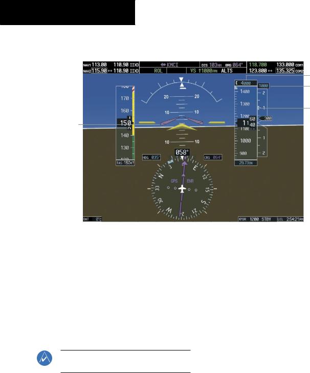
Vertical Speed Mode (VS)
In Vertical Speed Mode, the flight director acquires and maintains a Vertical Speed Reference. Current aircraft vertical speed (to the nearest 100 fpm) becomes the Vertical Speed Reference at the moment of Vertical Speed Mode activation. Vertical Speed Mode does not consider the relative position of the Selected Altitude in relation to the current aircraft altitude at the time of mode activation, so it is possible to use Vertical Speed Mode while not climbing/descending to the Selected Altitude.
Vertical Speed Mode is activated by pressing the VS Key;the‘VS’annunciationappearsintheAFCSStatusBox to indicate the active pitch mode, along with the Vertical SpeedReferencetotheright. TheVerticalSpeedReference is also displayed above the Vertical Speed Indicator. A VerticalSpeedReferenceBugcorrespondingtotheVertical Speed Reference is shown on the indicator.
190-00384-07 Rev.A |
Garmin G1000 Cockpit Reference Guide for the Cessna Nav III |
6-7 |
SECTION 6 – AUTOMATIC
FLIGHT CONTROL
Vertical Speed |
|
Vertical |
Selected Altitude Capture |
||
|
Speed |
||||
Mode Active |
|
Reference |
|
Mode Armed |
|
|
|
||||
|
|
|
|
|
|
Selected Altitude
Vertical Speed
Reference
Vertical Speed
Reference Bug
Command Bars Indicate Climb to Attain Vertical Speed
Figure 6-8 Vertical Speed Mode
Changing the Vertical Speed Reference
The Vertical Speed Reference (shown both in the AFCS Status Box and above/below the Vertical Speed Indicator) may be changed by:
•Using the NOSE UP/NOSE DN Keys
•By pressing the CWS Button, hand-flying the aircraft to attain a new Vertical Speed Reference, then releasing the CWS Button
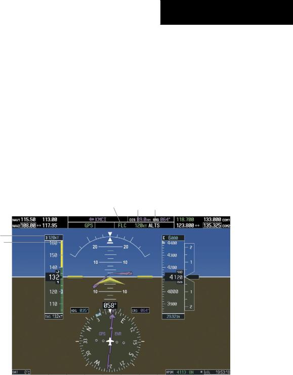
Flight Level Change Mode (FLC)
NOTE:The SelectedAltitude should be set before selecting Flight Level Change Mode.
Flight Level Change Mode is selected by pressing the FLC Key. When Flight Level Change Mode is active, the flight director continuously monitors Selected Altitude, airspeed, and altitude. This mode acquires and maintains the Airspeed Reference while climbing or descending to the Selected Altitude (shown above the Altimeter). The Airspeed Reference is set to the current airspeed upon mode activation. Flight Level Change Mode is indicated by an ‘FLC’ annunciation beside the Airspeed Reference in the AFCS Status Box. The Airspeed Reference is also displayed directly above the Airspeed Indicator, along with a bug corresponding to the Airspeed Reference along the tape.
Engine power must be adjusted to allow the autopilot to fly the aircraft at a pitch attitude corresponding to the Airspeed Reference and the desired flight profile (climb or
6-8 |
Garmin G1000 Cockpit Reference Guide for the Cessna Nav III |
190-00384-07 Rev.A |
SECTION 6 – AUTOMATIC
FLIGHT CONTROL
descent). Theflightdirectormaintainsthecurrentaltitude until either engine power or the Airspeed Reference are adjusted and does not allow the aircraft to climb or descend away from the Selected Altitude.
Changing the Airspeed Reference
The Airspeed Reference (shown in both the AFCS Status Box and above the Airspeed Indicator) may be adjusted:
•Using the NOSE UP/NOSE DN Keys
•BypressingtheCWSButton,hand-flyingtheaircraft to a new airspeed, then releasing the CWS Button to establish the new Airspeed Reference
Flight Level Change |
Airspeed |
Altitude Hold |
Mode Active |
Reference |
Mode Armed |
Airspeed Reference
Airspeed Reference Bug
Figure 6-9 Flight Level Change Mode
190-00384-07 Rev.A |
Garmin G1000 Cockpit Reference Guide for the Cessna Nav III |
6-9 |
SECTION 6 – AUTOMATIC
FLIGHT CONTROL
Vertical Navigation Modes (VPTH, ALTV)
NOTE: Pressing the CWS Button while Vertical Path Tracking Mode is active does not cancel the mode. The autopilot guides the aircraft back to the descent path upon release of the CWS Button.
NOTE: VNAV flight director pitch modes are available only in conjunction with GPS roll modes.
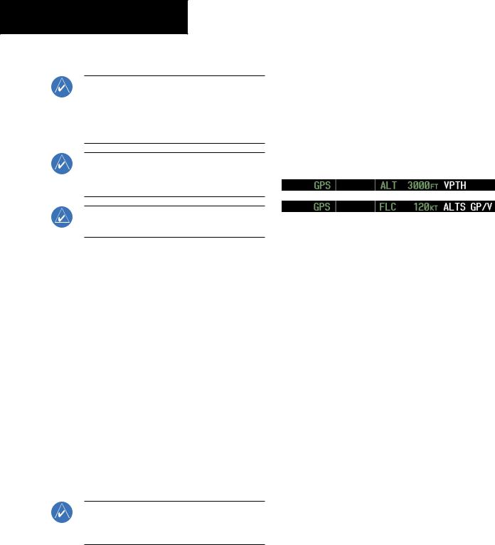
When a vertical profile (VNAV flight plan) is active and the VNV Key is pressed, Vertical Path Tracking Mode is armedinpreparationfordescentpathcapture. ‘VPTH’(or ‘/V’ when Glidepath or Glideslope Mode is concurrently armed) is annunciated in white in addition to previously armed modes. If applicable, the appropriate altitude capture mode is armed for capture of the next VNAV Target Altitude (ALTV) or the Selected Altitude (ALTS), whichever is greater.
NOTE: The Selected Altitude takes precedence over any other vertical constraints.
Vertical Navigation (VNAV) flight control is available for enroute/terminal cruise and descent operations when VNAV has been enabled and a VNAV flight plan (with at least one vertical waypoint) or direct-to with a vertical constrainthasbeenactivated. RefertotheGPSNavigation Section for more information on VNAV flight plans. The flight director may be armed for VNAV at any time, but no target altitudes are captured during a climb.
The Command Bars provide vertical profile guidance based on specified altitudes (entered manually or loaded from the database) at waypoints in the active flight plan or vertical direct-to. The appropriate VNAV flight control modes are sequenced by the flight director to follow the path defined by the vertical profile. Upon reaching the last waypoint in the VNAV flight plan, the flight director transitions to Altitude Hold Mode and cancels any armed VNAV modes.
Vertical Path Tracking Mode (VPTH)
NOTE:If another pitch mode key is pressed while Vertical Path Tracking Mode is selected, Vertical Path Tracking Mode reverts to armed.
Figure 6-10 Vertical Path Tracking Armed Annunciations
Priortodescentpathinterception,theSelectedAltitude must be set below the current aircraft altitude by at least 75 ft. For the flight director to transition from Altitude Hold to Vertical Path Tracking Mode, acknowledgment is required within five minutes of descent path capture by:
•Pressing the VNV Key
•Adjusting the Selected Altitude
Ifacknowledgmentisnotreceivedwithinoneminuteof descent path interception, the white ‘VPTH’ annunciation andtheVNVKeyannunciatorlightstarttoflash. Flashing continues until acknowledged or the descent path is intercepted. If the descent is not confirmed by the time of interception, Vertical Path Tracking Mode remains armed and the descent is not captured.
6-10 |
Garmin G1000 Cockpit Reference Guide for the Cessna Nav III |
190-00384-07 Rev.A |
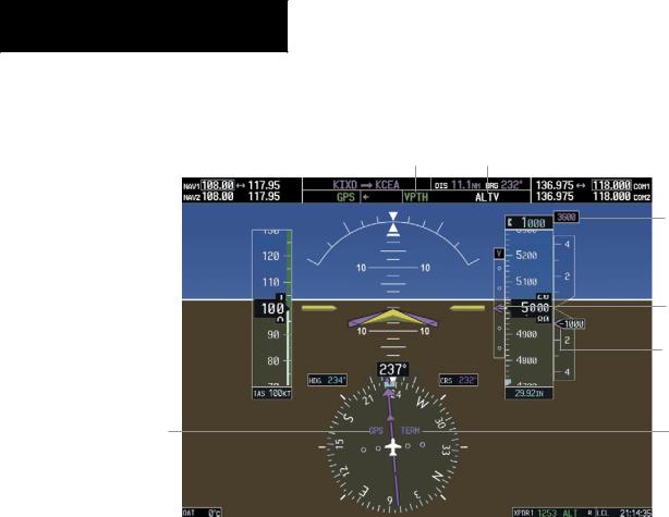
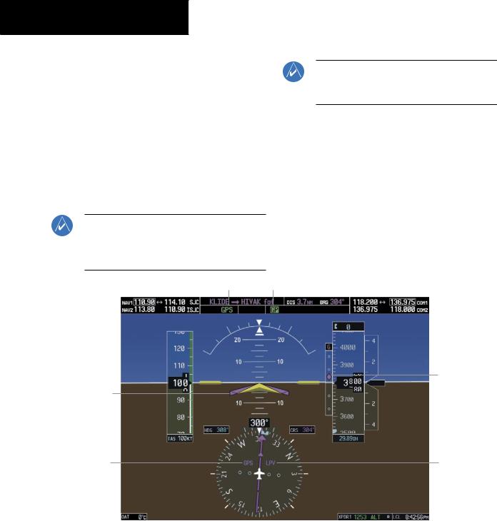
Inconjunctionwiththe“TOD[topofdescent]within1 minute” annunciation in the Navigation Data Box, VNAV indications (VNAV Target Altitude, vertical deviation, and vertical speed required) appear on the PFDs in magenta (Figure 6-11).
Altitude Hold Mode Active
HSI Set to GPS
SECTION 6 – AUTOMATIC
FLIGHT CONTROL
Vertical Path Tracking Armed, (Flashing Indicates Acknowledgment Required)
VNAV Target
Altitude
Selected Altitude Below
VNAV Target
Vertical Deviation
Indicator
Required Vertical
Speed Bug
Enroute Phase of
Flight
Figure 6-11 Vertical Path Capture
190-00384-07 Rev.A |
Garmin G1000 Cockpit Reference Guide for the Cessna Nav III |
6-11 |
SECTION 6 – AUTOMATIC
FLIGHT CONTROL
When a descent leg is captured (Figure 6-12), Vertical |
|
Path Tracking becomes active and tracks the descent pro- |
|
file. An altitude capture mode (‘ALTS’ or ‘ALTV’) is armed |
|
as appropriate. |
|
Vertical Path Tracking Active |
VNAV Target Altitude Capture Armed |
VNAV
Target
Altitude
Vertical
Deviation
Indicator
Required
Vertical
Speed Bug
Terminal
HSI Set to GPS Phase of
Flight
Figure 6-12 Vertical Path Tracking Mode
Automatic Pitch Hold Reversion
Several situations can occur while Vertical Path Tracking Mode is active which cause the flight director to revert to Pitch Hold Mode. Vertical Path Tracking and the appropriate altitude capture modes are armed for possible descent profile recapture if the vertical deviation:
•Exceeds 200 ft during an overspeed condition
•Experiencesadiscontinuityexceeding200ftdueto a flight plan change
•Becomes invalid due to excessive cross-track error, track angle error
•Cannot be computed for a leg type (such as a hold or procedure turn)
The following circumstances cause mode reversion without arming Vertical Path Tracking Mode:
•Navigation source manually changed from GPS
•CNCL VNV Softkey selected on the Active Flight Plan Page (MFD)
•All remaining vertical waypoints deleted from the flight plan
•Displays entering Reversionary Mode
Non-Path Descents
Pitch Hold, Vertical Speed, and Flight Level Change modes can also be used to fly non-path descents while
6-12 |
Garmin G1000 Cockpit Reference Guide for the Cessna Nav III |
190-00384-07 Rev.A |
VNAV flight control is selected. If the VS or FLC Key is pressed while Vertical Path Tracking Mode is selected, Vertical Path Tracking Mode reverts to armed along with the appropriate altitude capture mode to allow profile recapture.
Figure 6-13 Flight Level Change VNAV Non-Path Descent
To prevent immediate profile re-capture, the following must be satisfied:
•Atleasttensecondshavepassedsincethenon-path transition was initiated
•Verticaldeviationfromtheprofilehasexceeded250 ft, but is now less than 200 ft
Pressing the VNV Key twice re-arms Vertical Path Tracking for immediate profile re-capture.
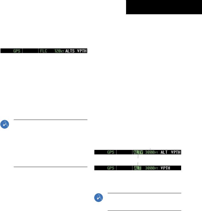
VNAV Target Altitude Capture Mode (ALTV)
NOTE:ArmedVNAVTargetAltitude and Selected Altitude capture modes are mutually exclusive. However, Selected Altitude Capture Mode is armed implicitly (not annunciated) whenever VNAV Target Altitude Capture Mode is armed. This ensures the SelectedAltitude is not violated during a change from VNAV Target Altitude Capture to SelectedAltitude Capture Mode close to Selected Altitude interception.
VNAV Target Altitude Capture is analogous to Selected Altitude Capture Mode and is armed automatically after the VNV Key is pressed and the next VNAV Target Altitude is to be intercepted before the Selected Altitude. The annunciation ‘ALTV’ indicates that the VNAV Target Altitude is to be captured. VNAV Target Altitudes are shown in the active flight plan or vertical direct-to, and canbeenteredmanuallyorloadedfromadatabase(seethe GPS Navigation Section for details). At the same time as “TOD within 1 minute” is annunciated in the Navigation
SECTION 6 – AUTOMATIC
FLIGHT CONTROL
Data Box, the VNAV Target Altitude is displayed above the Vertical Speed Indicator (see Figure 6-12). VNAV Target Altitudes can be modified until VNAV Target Altitude Capture Mode becomes active.
As the aircraft nears the VNAV Target Altitude, the flight director automatically transitions to VNAV Target Altitude Capture Mode with Altitude Hold Mode armed. This automatic transition is indicated by the green ‘ALTV’ annunciation flashing for up to ten seconds and the appearance of the white ‘ALT” annunciation. The VNAV Target Altitude is shown as the Altitude Reference beside the ‘ALTV’ annunciation.
At 50 ft from the VNAV Target Altitude, the flight director automatically transitions from VNAV Target Altitude Capture to Altitude Hold Mode and tracks the level leg. As Altitude Hold Mode becomes active, the white ‘ALT’ annunciation moves to the active pitch mode field and flashes green for ten seconds to indicate the automatic transition. The flight director automatically arms Vertical Path Tracking, allowing upcoming descent legs to be captured and subsequently tracked.
Altitude Reference (In This
Case, Equal To VNAV
Altitude Target)
Flash up to 10 sec, Indicating Automatic Transition
Figure 6-14 VNAV Altitude Capture
Changing the VNAV Target Altitude
NOTE: Pressing the CWS Button while in VNAV Target Altitude Capture Mode does not cancel the mode.
190-00384-07 Rev.A |
Garmin G1000 Cockpit Reference Guide for the Cessna Nav III |
6-13 |
SECTION 6 – AUTOMATIC
FLIGHT CONTROL
Changing the current VNAV Target Altitude while VNAV Target Altitude Capture Mode is active causes the flight director to revert to Pitch Hold Mode. Vertical Path Tracking and the appropriate altitude capture mode are armed in preparation to capture the new VNAV Target Altitude or the Selected Altitude, depending on which altitude is to be intercepted first.
VNAV target altitudes can be changed while editing the active flight plan (see the GPS Navigation Section for details).
Glidepath Mode (GP)
NOTE:Pressing the CWS Button while Glidepath Mode is active does not cancel the mode. The autopilotguidestheaircraftbacktotheglidepath upon release of the CWS Button.
GPS Approach Mode Active
Command Bars
Indicate Descent on
Glidepath
HSI Set to GPS
NOTE: Glidepath Mode is available only in installations with GIA 63W Integrated Avionics Units and WAAS is currently available.
Glidepath mode is used to track the WAAS-based glidepath. ArmingGlidepathMode(annunciatedinwhite as ‘GP’) requires:
•Approach supporting WAAS vertical guidance is loaded into the flight plan
•Expected availability of vertical guidance
•GPS Approach Mode is armed, after acquiring clearance for approach, prior to intercepting the WAAS glidepath (GPS is the selected navigation source and the APR Key is pressed; see GPS Approach Mode)
Glidepath Mode Active
Glidepath
Indicator
LPV Ap-
proach
Active
Figure 6-15 Glidepath Mode
6-14 |
Garmin G1000 Cockpit Reference Guide for the Cessna Nav III |
190-00384-07 Rev.A |
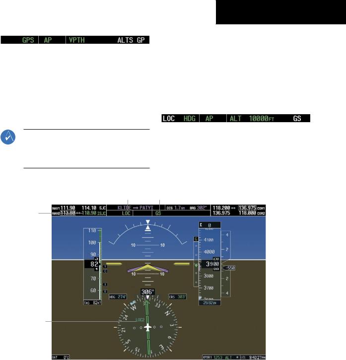
Figure 6-16 Glidepath Mode Armed
If vertical guidance becomes or is expected to become unavailable and the approach downgrades, Glidepath Mode is disarmed. When vertical guidance becomes available again, Glidepath Mode is automatically re-armed under GPS Approach Mode.
Glideslope Mode (GS)
NOTE:Pressingthe CWS ButtonwhileGlideslope Mode is active does not cancel the mode. The autopilot guides the aircraft back to the glideslope upon release of the CWS Button.
SECTION 6 – AUTOMATIC
FLIGHT CONTROL
Glideslope Mode is available for LOC/ILS approaches to capture and track the glideslope. Glideslope Mode is armed when:
•A valid localizer frequency is tuned
•LOC Approach Mode is armed (the APR Key is pressed and either LOC is the selected navigation source or a LOC/ILS approach is loaded into the flight plan; see LOC Approach Mode)
Figure 6-18 Glideslope Mode Armed
Once the localizer has been set as the navigation source,thelocalizerandglideslopecanbecaptured. Upon reaching the glideslope, the flight director transitions to Glideslope Mode and begins to intercept and track the glideslope.
Approach Mode Active |
Glideslope Mode Active |
Active ILS
Frequency
Tuned
Glideslope
Command Bars 
 Indicator
Indicate Descent on
Localizer/Glides-
lope Path
HSI Set to LOC2
Figure 6-17 Glideslope Mode
190-00384-07 Rev.A |
Garmin G1000 Cockpit Reference Guide for the Cessna Nav III |
6-15 |
SECTION 6 – AUTOMATIC
FLIGHT CONTROL
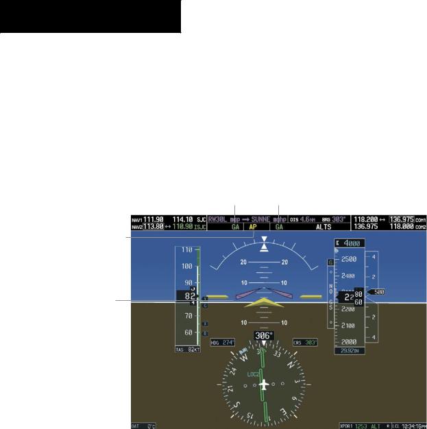
Go Around (GA) Mode
Pushing the GA Switch engages the flight director in a wings level, 7° pitch-up attitude, allowing the execution of a missed approach or a go around. This mode is a couple pitch and roll mode and is annunciated as ‘GA’ in both the pitch and roll active mode fields. Go Around Mode disengages the autopilot and arms Altitude Hold Mode automatically. Subsequent autopilot engagement is allowed. Attempts to modify the aircraft attitude (i.e., with the CWS Button or NOSE UP/NOSE DN keys) result in reversion to Pitch and Roll Hold modes.
Go Around Mode Active
Autopilot Disconnect Annunciation Flashes Yellow
5 sec
Command Bars
Indicate Climb
Figure 6-19 Go Around Mode
6-16 |
Garmin G1000 Cockpit Reference Guide for the Cessna Nav III |
190-00384-07 Rev.A |