- •Section 1: System Overview
- •1.1 PFD/MFD Controls
- •1.2 PFD Softkeys
- •1.3 MFD Softkeys
- •1.4 MFD Page Groups
- •1.5 Vertical Navigation
- •1.6 Backlighting
- •1.7 XM Radio - Automatic Muting
- •1.8 Database Updates
- •Jeppesen Aviation Database
- •Garmin Databases
- •Section 2: Flight Instruments
- •2.1 Airspeed Indicator
- •Speed Indication
- •Speed Ranges
- •Airspeed Trend Vector
- •Vspeed References
- •2.2 Attitude Indicator
- •2.3 Altimeter
- •Altitude Reference Bug
- •Altitude Trend Vector
- •Barometric Setting Box
- •Altitude Alerting
- •Metric Display
- •Low Altitude Annunciation
- •2.5 Marker Beacon Annunciations
- •2.6 Vertical Speed Indicator
- •2.7 Barometric Altitude Minimums
- •2.8 Horizontal Situation Indicator (HSI)
- •Course Pointer
- •Course Deviation Indicator (CDI)
- •Bearing Pointers and Information Windows
- •DME (optional)
- •Navigation Source
- •2.9 Wind Data
- •2.10 Generic Timer
- •3.1 Engine Display
- •3.2 Lean Display
- •Normally-aspirated Aircraft
- •Turbocharged Aircraft
- •3.3 System Display
- •4.1 Radio Status Indications
- •4.2 Volume
- •4.3 Automatic Squelch
- •4.4 Quickly Activating 121.500 MHz
- •4.5 Optional NAV Radios
- •DME Radio (optional)
- •ADF Radio (optional)
- •Auto-tuning on the PFD
- •Auto-tuning on the MFD
- •4.7 Transponder
- •Mode Selection
- •Reply Status
- •Code Selection
- •Flight ID Reporting
- •5.1 COM Radio Selection
- •5.2 Marker Beacon Receiver
- •Marker Beacon Signal Sensitivity
- •5.3 Nav Radio Audio Selection
- •5.4 Intercom System (ICS) Isolation
- •5.5 Intercom Squelch Control
- •5.6 Digital Clearance Recorder and Player
- •6.1 AFCS Controls
- •6.2 Flight Director Operation
- •Activating the Flight Director
- •Command Bars
- •AFCS Status Box
- •6.3 Flight Director Modes
- •Pitch Modes
- •Roll Modes
- •6.4 Autopilot Operation
- •Flight Control
- •Engaging the Autopilot
- •Control Wheel Steering
- •Disengaging the Autopilot
- •6.5 Example Procedures
- •Departure
- •Intercepting a VOR Radial
- •Flying a Flight Plan/GPS Course
- •Descent
- •Approach
- •Go Around/Missed Approach
- •6.6 AFCS Annunciations and Alerts
- •AFCS Status Alerts
- •Overspeed Protection
- •Section 7: Navigation
- •7.1 Navigation Map Page
- •Select the MAP Page Group
- •Direct-to Navigation from the MFD
- •Direct-to Navigation from the PFD
- •7.3 Navigating an Example Flight Plan
- •7.4 Airport Information
- •Select the Airport Information Page
- •7.5 Intersection Information
- •Select the Intersection Information Page
- •7.6 NDB Information
- •Select the NDB Information Page
- •7.7 VOR Information
- •Select the VOR Information Page
- •7.8 User Waypoint Information Page
- •7.9 Nearest Airports
- •Nearest Airport Information on the MFD
- •Nearest Airports Information on the PFD
- •7.10 Nearest Intersections
- •Select the Nearest Intersections Page
- •7.11 Nearest NDB
- •Select the Nearest NDB Page
- •7.12 Nearest VOR
- •Select the Nearest VOR Page
- •7.13 Nearest User Waypoint
- •Select the Nearest User Waypoint Page
- •7.14 Nearest Frequencies
- •Select the Nearest Frequencies Page
- •7.15 Nearest Airspaces
- •Select the Nearest Airspaces Page
- •Section 8: Flight Planning
- •8.1 User Defined Waypoints
- •Select the User WPT Information Page
- •Create User Waypoints from the Navigation Map Page
- •8.2 Viewing the Active Flight Plan
- •8.3 Activate a Stored Flight Plan
- •8.4 Activate a Flight Plan Leg
- •8.5 Stop Navigating a Flight Plan
- •8.6 Invert Active Flight Plan
- •8.7 Create a New Flight Plan
- •Create a New Flight Plan Using the MFD
- •Create a New Flight Plan Using the PFD
- •8.8 Enter an Airway in a Flight Plan
- •8.9 Load a Departure
- •8.10 Load an Arrival
- •8.11 Load an Approach
- •8.13 Store a Flight Plan
- •8.14 Edit a Stored Flight Plan
- •8.15 Delete a Waypoint from the Flight Plan
- •8.16 Invert and Activate a Stored Flight Plan
- •8.17 Copy a Flight Plan
- •8.18 Delete a Flight Plan
- •8.19 Graphical Flight Plan Creation
- •8.20 Trip Planning
- •Section 9: Procedures
- •9.1 Arrivals and Departures
- •Load and Activate a Departure Procedure
- •Load and Activate An Arrival Procedure
- •9.2 Approaches
- •Load and/or Activate an Approach Procedure
- •Activate An Approach in the Active Flight Plan
- •Section 10: Hazard Avoidance
- •10.1 Customizing the Hazard Displays on the Navigation Map
- •10.2 STORMSCOPE® (Optional)
- •Displaying Stormscope Lightning Data on the Navigation Map Page
- •Stormscope Page
- •10.3 XM Weather (Service Optional)
- •Displaying METAR and TAF information on the Airport Information Page
- •Displaying Weather on the Weather Data Link Page
- •Weather Products & Symbols
- •Weather Product Age
- •10.4 Traffic Systems
- •10.7 Terrain and Obstacle Proximity
- •Displaying Terrain and Obstacles on the Terrain Proximity Page
- •Displaying Terrain and Obstacles on the Navigation Map
- •10.8 Terrain Awareness & Warning System (TAWs) Display (Optional)
- •Displaying Terrain on the TAWS Page
- •Enable/Disable Aviation Data
- •TAWS Inhibit
- •Manual System Test
- •Forward Looking Terrain Avoidance (FLTA)
- •Premature Descent Alert (PDA)
- •Excessive Descent Rate Alert (EDR)
- •Displaying Terrain and Obstacles on the Navigation Map
- •Pop-up Alerts
- •TAWS Alerts Summary
- •Alert Annunciations
- •11.1 Reversionary Mode
- •11.2 Abnormal COM Operation
- •11.3 Unusual Attitudes
- •11.4 Stormscope operation with loss of Heading Input
- •11.5 Hazard Displays with Loss of GPS Position
- •11.6 Dead Reckoning
- •12.1 Alert Level Definitions
- •12.2 NAV III Aircraft Alerts
- •WARNING Alerts
- •CAUTION Alerts
- •12.3 CO Guardian Messages
- •12.4 AFCS Alerts (182 & 206 Only)
- •System Status Annunciation
- •12.5 TAWS Alerts
- •12.6 Other G1000 Aural Alerts
- •12.7 G1000 System Annunciations
- •12.8 G1000 System Message Advisories
- •MFD & PFD Message Advisories
- •Database Message Advisories
- •GMA 1347 Message Advisories
- •GIA 63 Message Advisories
- •GIA 63W Message Advisories
- •GEA 71 Message Advisories
- •GTX 33 Message Advisories
- •GRS 77 Message Advisories
- •GMU 44 Message Advisories
- •GDL 69A Message Advisories
- •GDC 74A Message Advisories
- •Miscellaneous Message Advisories
- •Index
5.3NAV RADIO AUDIO SELECTION
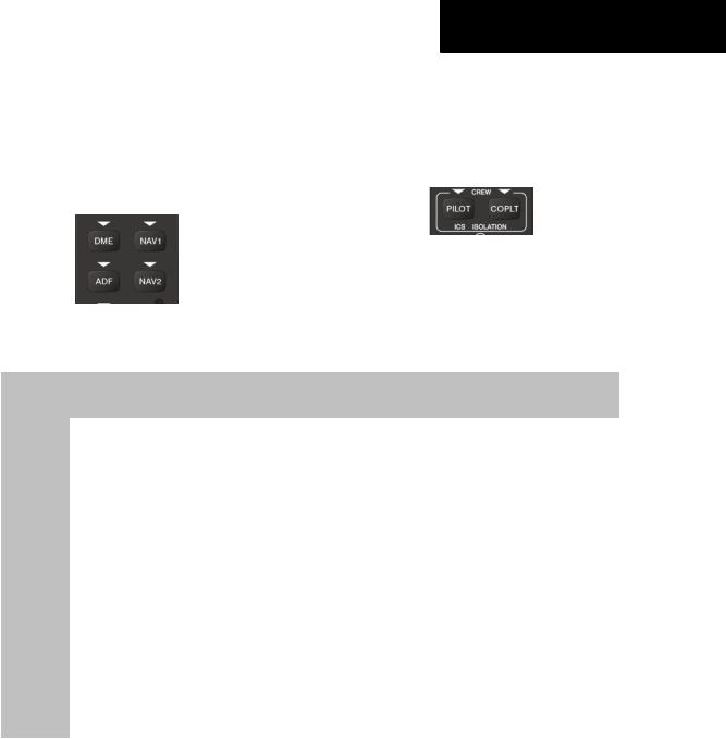
Pressing DME, ADF, NAV1, or NAV2 selects and deselects the audio source and activates the annunciator. Selected audio can be heard over the headset and the speakers. These four keys can be selected individually or together.
SECTION 5 – AUDIO PANEL
5.4INTERCOM SYSTEM (ICS) ISOLATION
Press the PILOT and/or COPLT Key to select who is isolated from hearing the Nav/Com radios and music. Selection scenarios are addressed in Table 5-1.
|
|
|
|
|
|
|
Figure 5-6 ICS Isolation |
|
|
Figure 5-5 |
Navigation Radios |
|
|
|
|
||
|
|
|
|
|
|
|
|
|
Mode |
|
PILOT KEY |
COPLT KEY |
|
Pilot Hears |
Copilot Hears |
Passenger |
|
|
ANNUNCIATOR |
ANNUNCIATOR |
Hears |
|||||
|
|
|
|
|||||
|
|
|
|
|
|
Selected radios; |
Selected radios; |
Selected radios; |
ALL |
|
|
OFF |
OFF |
|
pilot; copilot; |
pilot; copilot; |
pilot; copilot; |
|
|
|
passengers; |
passengers; |
passengers; |
|||
|
|
|
|
|
|
|||
|
|
|
|
|
|
MUSIC 1 |
MUSIC 1 |
MUSIC 2 |
|
|
|
|
|
|
Selected radios; |
Copilot; |
Copilot; |
PILOT |
|
|
ON |
OFF |
|
passengers; |
passengers; |
|
|
|
|
pilot |
|||||
|
|
|
|
|
|
MUSIC 1 |
MUSIC 2 |
|
|
|
|
|
|
|
|
||
|
|
|
|
|
|
|
|
|
|
|
|
|
|
|
Selected radios; |
|
Selected radios; |
COPILOT |
|
OFF |
ON |
|
pilot; passengers; |
Copilot |
pilot; passengers; |
|
|
|
|
|
|
|
MUSIC 1 |
|
MUSIC 2 |
|
|
|
|
|
|
|
|
|
CREW |
|
|
ON |
ON |
|
Selected radios; |
Selected radios; |
Passengers; |
|
|
|
pilot; copilot |
pilot; copilot |
MUSIC 2 |
|||
|
|
|
|
|
|
|||
|
|
|
|
|
|
|
|
|
|
|
|
|
Table 5-1 |
ICS Isolation Modes |
|
|
190-00384-07 Rev.A |
Garmin G1000 Cockpit Reference Guide for the Cessna Nav III |
5-3 |
SECTION 5 – AUDIO PANEL
5.5INTERCOM SQUELCH CONTROL
Select manual squelch for intercom audio by pressing the MAN SQ Key to light the annunciator.
Pressing the small VOL/SQ Knob now switches between volume and squelch adjustment by lighting VOL or SQ respectively.
•Pressing the MKR/MUTE Key while playing a memory block stops play.
•Pressing the PLAY Key during play begins playing the previously recorded memory block. Each subsequentpressofthePLAYKeywillbeginplaying the next previously recorded block.
If a COM input signal is detected while playing, play is halted and the new COM input signal is recorded as the latest block.
Figure 5-7 Volume/Squelch Control
5.6DIGITAL CLEARANCE RECORDER AND PLAYER
Each reception of primary active COM audio is automaticallyrecordedinamemoryblock. Whenthenext transmissionisreceived,itisrecordedinthenextmemory block, and so on. Once the 2.5 minutes of recording time has been reached, the recorder begins recording over the stored memory blocks, starting from the oldest block. Powering off the unit automatically clears all recorded blocks.
Figure 5-8 Clearance Recorder Play Key
•PressingthePLAYKeyonceplaysthelatestrecorded memory block, then returns to normal operation.
5-4 |
Garmin G1000 Cockpit Reference Guide for the Cessna Nav III |
190-00384-07 Rev.A |
SECTION 6:AUTOMATIC FLIGHT
CONTROL
NOTE: The Aircraft Flight Manual (AFM) always supersedes the information in this guide. This section only applies to the GFC 700 Automatic Flight Control System (AFCS).
NOTE: The GFC 700AFCS is not available for the Cessna 172.
6.1AFCS CONTROLS
The following dedicated AFCS keys are located on the bezels of the PFD and MFD:
Figure 6-1 Dedicated AFCS Controls
The following AFCS controls are located in the cockpit separately from the MFD:
•AP DISC Switch (Autopilot Disconnect)
Disengages the autopilot and interrupts pitch trim operation. The red AP DISC Switch is located
SECTION 6 – AUTOMATIC
FLIGHT CONTROL
forward of the MET Switch on the pilot’s control wheel left grip. This switch may be used to acknowledge an autopilot disconnect and mute the associated aural tone.
•CWS Button (Control Wheel Steering)
Momentarily disengages the autopilot and synchronizes the flight director’s Command Bars with the current aircraft pitch (if not in Glideslope Mode) and roll (if in Roll Hold Mode). The CWS
Buttonislocatedonthetopofthepilot’scontrol wheel right grip. Upon release of the CWS Button, the flight director may establish new reference points, depending on the current pitch and roll modes.
•GA Switch (Go-Around)
Disengages the autopilot, selects flight director GoAround Mode, and activates the missed approach.
The GA Switch is located on the instrument panel above the throttle.
•MET Switch (Manual Electric Trim)
The MET Switch is located on the pilot’s control wheel left grip. This composite switch is split into left and right sides. The left switch is the ARM contact and the right switch controls the DN (forward) and UP (rearward) contacts. The MET ARM switch can be used to disengage the autopilot and to acknowledge an autopilot disconnect alert and mute the associated aural tone. Manual trim commands are generated only when both sides of the switch are operated simultaneously. If either side of the switch is active separately for more than threeseconds,METfunctionisdisabledand‘PTRM’ isdisplayedastheAFCSStatusAnnunciationonthe PFD. Thefunctionremainsdisableduntilbothsides of the switch are inactivated.
190-00384-07 Rev.A |
Garmin G1000 Cockpit Reference Guide for the Cessna Nav III |
6-1 |