

Ris_DSP / AD_DSP_selection_guide
.pdfADSP-21065L
Low-Cost Entry-Point to the SHARC® DSP Family
Features |
|
Applications |
•16K 32-bit dual-ported on-chip memory (544 KBits configurable)
•64M x 32-bit word external address space
•198 MFLOPS (32-bit floating-point)
•198 MOPS (32-bit fixed-point)
•Glueless SDRAM interface
•2 serial transmit/receive ports support
32-channel TDM
•I 2S mode supports up to 16 channels
•2 timers with event capture and PWM options
•12 programmable I/O pins
•10 DMA channels
•Glueless multiprocessing with 2 ADSP-21065L’s
•Code compatible with all SHARC family members
•3.3 volt, 208-pin MQFP, 196 MBGA
•Digital audio
•Keyless entry using voice analysis/recognition
•Bar code scanners
•Imaging
•Ultrasound equipment
•Digital oscilloscopes
•Fingerprint recognition
|
Price* |
Model |
MHz Pin/Pkg (1000) |
|
|
ADSP-21065LKS-240* 60 208-MQFP $19.50
ADSP-21065LKS-264 66 208-MQFP $37.50 ADSP-21065LKCA-240 60 196-MBGA $38.00
ADSP-21065LKCA-264 66 196-MBGA $39.50 ADSP-21065LCS-240 60 208-MQFP $37.50
L Indicates 3.3 Volt Operation
K = Commercial Temp (0ºC to +85ºC case) C = Industrial Temp (-40ºC to +100ºC case) *All pricing is budgetary – subject to change
Development Tools
ADDS-2106X-WKSHP |
DSP Workshop |
ADDS-21065L-EZLITE |
Evaluation Kit |
VDSP-SHARC-PC-FULL |
VisualDSP++ |
VDSP-SHARC-PCFLOAT VisualDSP++ Floating License |
|
ADDS-APEX-ICE |
USB-Based Emulator |
ADDS-SUMMIT-ICE |
PCI-Based Emulator |
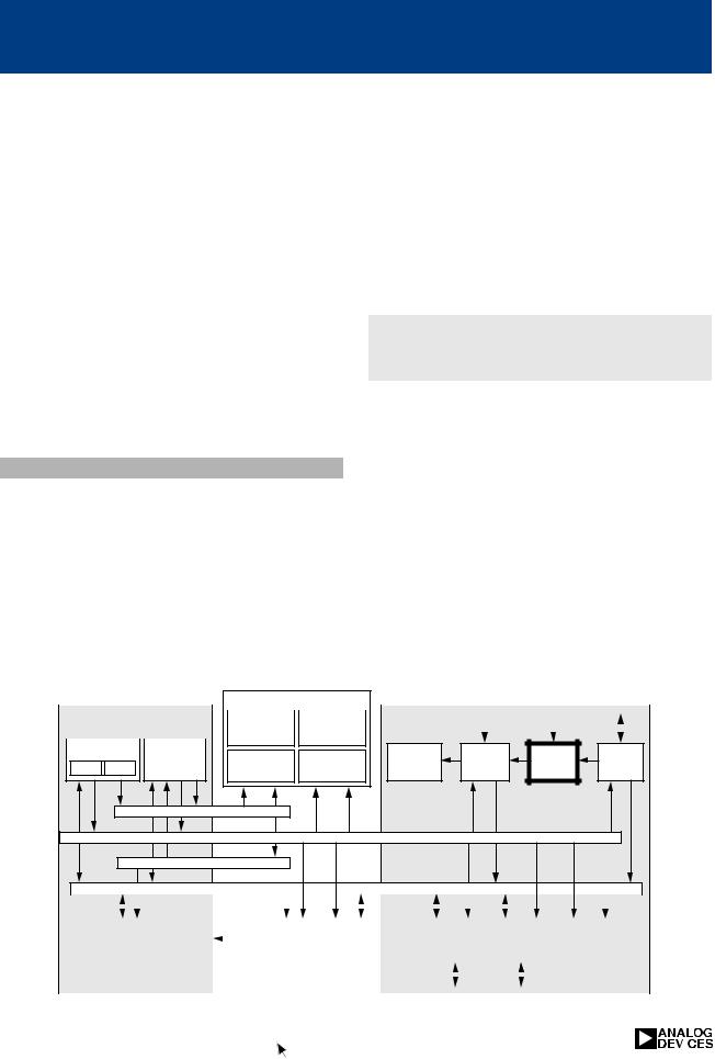
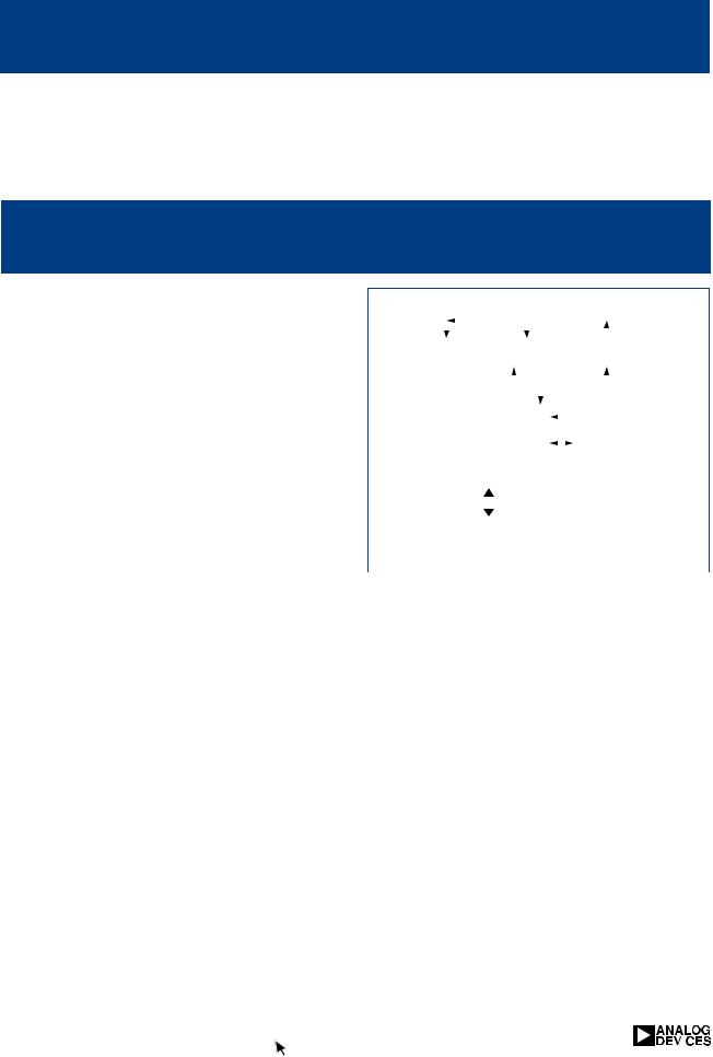
Core Processor |
|
|
Dual-Ported SRAM |
|
|
JTAG |
7 |
|||
|
|
|
|
|
|
|
0 |
|
Test and |
|
|
Timer 1 |
Timer 2 |
Instruction |
Two Independent |
|
|
Emulation |
|
||
|
|
Block |
|
|
||||||
|
|
|
Cache |
Dual-Ported Blocks |
|
Block 1 |
|
|
||
|
|
|
32 x 48-Bit |
|
|
|
|
|
||
|
|
|
Processor Port |
I/O Port |
External Port |
|
||||
|
|
|
Addr |
Data |
Data |
Addr |
SDRAM Interface |
|
||
|
|
|
|
|
|
|||||
|
|
|
Addr |
Data |
Data |
|
Addr |
|
||
|
|
|
|
|
|
|||||
DAG1 |
DAG2 |
Program |
|
|
|
|
|
Multiprocessor |
|
|
|
|
|
|
|
Interface |
|
||||
8 x 4 x 32 |
8 x 4 x 32 |
Sequencer |
|
|
|
|
|
|
||
|
|
|
|
|
|
|
||||
|
|
|
|
|
IOD |
|
IOA |
Host Port |
|
|
|
|
|
24 |
|
48 |
|
17 |
|
||
|
PM Address Bus |
|
|
|
|
|||||
|
|
|
|
|
|
|
|
|||
|
|
|
|
|
|
|
|
|
||
|
|
|
|
|
|
|
|
|
Address |
24 |
|
DM Address Bus |
32 |
|
|
|
|
|
Mux |
|
|
|
|
|
|
|
|
Bus |
|
|||
|
|
|
|
|
|
|
|
|||
|
PM Data Bus |
48 |
|
|
|
|
|
|
|
|
Bus |
|
|
|
|
|
|
Data |
32 |
||
|
|
|
|
|
|
|
|
|||
Connect |
|
40 |
|
|
|
|
|
Mux |
|
|
(PX) |
DM Data Bus |
|
|
|
|
|
Bus |
|
||
|
|
|
|
|
|
|
||||
|
Data |
|
|
|
IOP |
|
|
DMA |
4 |
|
|
|
|
|
|
|
|
|
|||
|
Register |
|
|
|
|
Controller |
|
|
||
|
|
|
|
Registers |
|
|
|
|||
|
File |
|
|
|
|
|
|
|
|
|
|
|
|
|
(Memory |
|
|
|
|
|
|
|
|
|
|
|
|
|
|
(2 Rx, 2 Tx) |
|
|
|
16 x 40-Bit |
Barrel |
|
|
Mapped) |
|
|
SPORT 0 |
|
|
|
|
|
|
|
|
|
||||
|
|
|
|
|
|
|
|
|||
Multiplier |
Shifter |
ALU |
|
Control, |
|
|
|
I2S |
|
|
|
|
|
|
|
Status, and |
|
|
SPORT 1 |
(2 Rx, 2 Tx) |
|
|
|
|
|
Data Buffers |
|
|
I2S |
|
||
|
|
|
|
|
|
|
|
|
|
|
|
|
|
|
|
I/O Processor |
|
|
|||
40 DSP Selection Guide |
http://www.analog.com/dsp |
|
|
|
|||
|
|
|
|
|
|
|
|

The ADSP-2199x family of mixed-signal DSPs provides a single-chip high-performance solution with signal processing and mixed-signal integration for both current and future embedded control and signal processing applications. These products combine the ADSP-219x codecompatible DSP core, multichannel, high-reso- lution analog/ digital conversion, the right mix of embedded control peripherals, and comprehensive development tools. A variety of memory sizes address emerging market requirements with power efficient and high-performance solutions.
Development Tools
All ADSP-219x products, including the ADSP2199x series are supported by ADI’s CROSSCORE™ software and hardware development tools. The development tools suite includes the VisualDSP++™ integrated software development environment with the C/C++ compiler, VisualDSP++ Kernel (VDK), advanced plotting
ADSP-2199x Family
Mixed Signal DSPs
tools and statistical profiling to quickly identify bottlenecks and reduce development time. The tools suite also includes a low-cost EZ-KIT Lite™ evaluation platform. The EZ-KIT Lite can also be extended with JTAG In-circuit Emulation (ICE) for full control of software debugging. PCI and USB versions are of the emulator available.
Development Tools
ADDS-21990-EZLITE |
Evaluation Kit |
VDSP-21XX-PC-FULL |
VisualDSP++ |
VDSP-21XX-PCFLOAT |
VisualDSP++ Floating License |
ADDS-APEX-ICE |
USB-Based Emulator |
ADDS-SUMMIT-ICE |
PCI-Based Emulator |
Embedded Control applications support can be obtained at mcgapps@analog.com. Users can also obtain additional support, free software upgrades, and sample code by visiting the Motor Control Web site at www.analog.com/motorcontrol
|
|
|
Program |
Data |
|
|
Device |
Package |
Max MIPS |
RAM Words |
RAM Words |
ADC |
Status |
|
|
|
|
|
|
|
ADSP-21990 |
ST, BC |
160 |
4K |
4K |
14-Bit |
Samples Now |
|
|
|
|
|
20 MSPS |
Release 2Q02 |
ADSP-21991 |
ST, BC |
160 |
32K |
8K |
14-Bit |
Samples 3Q02 |
|
|
|
|
|
20 MSPS |
Release 4Q02 |
Packages: ST = Thin Quad Flat Pack (LQFP)
BC = Mini Ball Grid Array (10 x 10 mm)
|
http://www.analog.com/motorcontrol |
DSP Selection Guide 41 |
|
|
ADSP-21990
Mixed Signal DSP
Features |
|
Benefits |
•160 MHz, ADSP-219x DSP core
•8-Channel, 14-Bit, 20 MSPS ADC
•On-chip voltage reference and power-on-reset
•4K words program memory RAM
•4K words data memory RAM
•External memory interface (to 1M Word)
•Embedded Control Peripherals
–Three-phase PWM generation unit
–Incremental encoder interface unit
–Dual auxiliary PWM outputs
–Watchdog timer
–Three 32-Bit, general purpose timers
–16-Bit general purpose flag I/O port
–Peripheral interrupt controller
–Synchronous serial (SPORT) and SPI
–Communications ports
•ADSP-219x core delivers highest performance mixed-signal DSP for control designs with up to 160 MIPS sustained performance
•Code compatible solution ensures investment protection with lower software cost
•State-of-the-art development tools
•Integrated single-chip pin-compatible
solutions facilitate high-performance design with higher reliability, reduces development time with lower overall system cost
•External memory interface provides direct access from DSP to external memory
for data or instruction
•Fabricated in high-speed, low power consumption, CMOS process
|
|
|
|
|
|
|
|
|
|
|
|
|
|
|
|
|
|
|
|
|
|
|
|
|
|
|
Development Tools |
|
|
|
|
|
|
|
||||||||||||
|
Applications |
|
|
|
|
|
|
|
|
|
|
|
|
|
|
|
|
|
|
|
|
|
|
|
|
|
|
|
|
|
||||||||||||||||
|
|
|
|
|
|
|
|
|
|
|
|
|
|
|
|
|
ADDS-21990-EZLITE |
|
Evaluation Kit |
|
|
|
|
|
|
|
||||||||||||||||||||
|
|
|
|
|
|
|
|
|
|
|
|
|
|
|
|
|
|
|
|
|
|
|
|
|
|
|
|
|
||||||||||||||||||
|
• Industrial motor drives |
|
|
|
|
|
|
|
|
|
|
|
|
|
|
|
|
VDSP-21XX-PC-FULL |
|
VisualDSP++ |
|
|
|
|
|
|
|
|||||||||||||||||||
|
|
|
|
|
|
|
|
|
|
|
|
|
|
|
|
|
VDSP-21XX-PCFLOAT |
|
VisualDSP++ Floating License |
|||||||||||||||||||||||||||
|
• Un-interruptible power supplies |
|
|
|
|
|
|
|
|
|
|
|
|
|
|
|||||||||||||||||||||||||||||||
|
|
|
|
|
|
|
|
|
|
|
|
|
|
ADDS-APEX-ICE |
|
USB-Based Emulator |
|
|
|
|
|
|||||||||||||||||||||||||
|
• Optical networking control |
|
|
|
|
|
|
|
|
|
|
|
|
|
|
|
|
|
|
|
|
|
|
|||||||||||||||||||||||
|
|
|
|
|
|
|
|
|
|
|
|
|
|
|
|
|
ADDS-SUMMIT-ICE |
|
PCI-Based Emulator |
|
|
|
|
|
||||||||||||||||||||||
|
• Data acquisition systems |
|
|
|
|
|
|
|
|
|
|
|
|
|
|
|
|
|
|
|
|
|
|
|||||||||||||||||||||||
|
|
|
|
|
|
|
|
|
|
|
|
|
|
|
|
|
|
|
|
|
|
|
|
|
|
|
|
|
|
|
|
|
|
|
|
|
|
|
|
|
|
|
||||
|
• Test and measurement systems |
|
|
|
|
|
|
|
|
|
|
|
|
|
|
|
|
|
|
|
|
|
|
|
|
|
|
|
|
|
|
|
|
|
|
|
|
|
|
|
||||||
|
• Portable |
|
|
|
|
|
|
|
|
|
|
|
|
|
|
|
|
|
|
|
|
|
|
|
|
|
|
|
|
|
|
|
|
|
|
|
|
|
|
|
|
|
|
|||
|
|
|
|
|
|
|
|
|
|
|
|
|
|
|
|
|
|
|
|
|
|
|
|
|
|
|
|
|
|
|
|
|
|
|
|
|
|
|
|
|
|
|
||||
|
Instrumentation |
|
|
|
|
|
|
|
|
|
|
|
|
|
|
|
|
|
|
|
|
|
|
|
|
|
|
|
|
|
|
|
|
|
|
|
|
|
|
|
|
|
|
|
||
|
|
|
|
|
|
Clock Gen/PLL |
|
|
|
|
|
|
|
|
|
|
|
|
|
|
|
|
|
|
|
|
|
|
|
|
|
|
|
|
|
|
|
|
||||||||
|
• Intelligent sensors |
|
|
|
|
|
|
|
|
|
|
|
|
|
|
|
|
|
|
|
|
|
|
|
|
|
|
|
|
|
|
|
|
|
|
|
|
|
|
|
|
|
|
|
||
|
|
|
|
|
|
160 MHz |
|
|
|
|
To |
|
|
To |
|
|
4k x 24 |
|
|
|
|
|
|
|
|
|
|
|
|
|
|
|
||||||||||||||
|
• Robotic control |
|
|
|
|
|
|
|
|
|
|
|
|
|
|
|
|
|
|
|
|
|
|
|
|
|
|
|
|
|
||||||||||||||||
|
|
JTAG |
|
|
|
|
|
32k x 24 |
|
|
8k x 16 |
|
|
|
|
|
|
|
|
|
|
|
|
|
|
|
|
|
||||||||||||||||||
|
|
|
|
|
|
|
|
|
|
|
PM ROM |
|
|
|
|
|
|
|
|
|
|
|
|
|
|
|||||||||||||||||||||
|
|
|
|
|
Test and |
|
ADSP-219x |
|
|
|
PM RAM |
|
|
DM RAM |
|
|
|
|
|
|
|
|
|
|
|
|
|
|
|
|
|
|
|
|
||||||||||||
|
|
|
|
|
Emulation |
|
|
|
DSP |
|
|
|
|
|
|
|
|
|
|
|
|
|
|
|
|
|
|
|
|
|
|
|
|
|
|
|
|
|
|
|
||||||
|
|
|
|
|
|
|
|
|
|
|
|
|
|
|
|
|
|
|
|
|
|
|
|
|
|
|
|
|
|
|
|
|
|
|
|
|
|
|
|
|
|
|||||
|
|
|
|
|
|
|
|
|
|
|
|
|
|
|
|
|
|
|
|
|
|
|
|
|
|
|
|
|
|
|
|
|
|
|
|
|
|
|
|
Address |
|
|
||||
|
|
|
|
|
|
|
|
|
|
|
|
|
|
|
|
|
|
|
|
|
|
|
|
|
|
|
|
|
|
|
|
|
|
|
|
|
|
|
|
|
||||||
|
|
|
|
|
|
|
|
|
|
|
|
|
|
|
|
|
|
|
|
|
|
|
|
|
|
|
|
|
|
|
|
|
|
|
|
External |
|
Data |
|
|
|
|
|
|||
|
|
|
|
|
|
|
|
|
Bus |
|
|
|
|
|
|
|
|
|
|
|
|
|
|
|
|
|
|
|
|
|
|
|
|
|
Memory |
|
|
|
|
|
|
|||||
|
|
|
|
|
|
|
|
|
|
|
|
|
|
|
|
|
|
|
|
|
|
|
|
|
|
|
|
|
|
|
|
|
|
|
|
|
|
|
|
|
|
|||||
|
|
|
|
|
|
|
|
|
|
|
|
|
|
|
|
|
|
|
|
|
|
|
|
|
|
|
|
|
|
|
|
|
|
|
|
Interface |
|
Control |
|
|
|
|
|
|||
|
|
|
|
|
|
|
|
|
|
|
|
|
|
|
|
|
|
|
|
|
|
|
|
|
|
|
|
|
|
|
|
|
|
|
|
(EMI) |
|
|
|
|
|
|
||||
|
|
|
|
|
|
|
|
|
|
|
|
|
|
|
|
|
|
|
|
|
|
|
|
|
|
|
|
|
|
|
|
|
|
|
|
|
|
|
|
|
|
|
|
|||
|
|
|
|
|
|
|
|
|
|
|
|
|
|
|
|
|
|
|
|
|
|
|
|
|
|
|
|
|
|
|
|
|
|
|
|
|
|
|
|
|
|
|
|
|
|
|
|
|
|
|
|
|
|
|
|
|
I/O Registers |
|
|
|
|
|
|
|
|
|
|
|
|
|
|
|
|
|
|
|
|
|
|
|
|
|
|
|
|
|
|
|
|||||
|
|
|
|
|
|
|
|
|
|
|
|
|
|
|
|
|
|
|
|
|
|
|
|
|
|
|
|
|
|
|
|
|
|
|
|
|
|
MEMDMA |
|
|
|
|
|
|
||
|
|
|
|
|
|
|
|
|
|
|
|
|
Peripheral Interface Bus/Peripheral DMA |
|
|
|
|
|
||||||||||||||||||||||||||||
|
|
|
|
|
|
|
|
|
|
|
|
|
|
|
|
|
|
|
|
|
||||||||||||||||||||||||||
|
|
|
|
|
|
|
|
|
|
|
|
|
|
|
|
|
|
|
|
|
|
|||||||||||||||||||||||||
|
|
|
|
|
|
|
|
|
|
|
|
|
|
|
|
|
|
|
|
|
|
|
|
|
|
|
|
|
|
|
|
|
|
|
|
|
|
|
|
|
|
|
|
|
|
|
|
|
|
|
|
|
|
|
|
|
|
|
|
|
|
|
|
|
|
|
|
|
|
|
|
|
|
|
|
|
|
|
|
|
|
|
|
|
|
|
|
|
|
|
|
|
|
|
|
|
|
|
|
|
|
|
|
|
|
|
|
|
|
|
|
|
|
|
|
|
|
|
|
|
|
|
|
|
|
|
|
|
|
|
|
|
|
|
|
|
|
|
|
|
|
|
|
|
|
|
|
|
Encoder |
|
|
|
|
|
|
Timer 0 |
|
|
|
|
|
|
|
|
|
|
|
|
|
|
|
|
|
|
ADC Control |
|
POR |
|
|
|
|||||||
|
|
|
|
|
PMW |
|
|
Auxiliary |
|
|
|
Timer 1 |
|
|
|
|
SPI |
|
|
|
|
|
Watch |
|
Interrupt |
|
|
|
|
|
||||||||||||||||
|
|
|
|
|
Generator |
|
Interface |
|
PWM |
|
|
|
|
|
|
|
Flag |
|
Comms |
|
|
SPORT |
|
|
Dog |
|
Control |
|
|
|
|
|
|
|
|
|
|
|||||||||
|
|
|
|
|
|
|
Unit |
|
|
|
Timer 2 |
|
I/O |
|
|
|
|
|
|
|
|
|
|
|
|
|
|
|
||||||||||||||||||
|
|
|
|
|
Unit |
|
(& EET) |
|
Unit |
|
|
|
|
|
|
|
|
|
|
Port |
|
|
|
|
|
|
Timer |
|
(ICNTL) |
|
14-Bit ADC |
|
VREF |
|
|
|
||||||||||
|
|
|
|
|
|
|
|
|
|
|
|
|
|
|
|
|
|
|
|
|
|
|
|
|
|
|
|
|
|
|
|
|
|
|
|
|
|
|
||||||||
|
|
|
|
|
|
|
|
|
|
|
|
|
|
|
|
|
|
|
|
|
|
|
|
|
|
|
|
|
|
|
|
|
|
|
|
|
|
|
|
|
|
|||||
|
|
|
|
|
|
|
|
|
|
|
|
|
|
|
|
|
|
|
|
|
|
|
|
|
|
|
|
|
|
|
|
|
|
|
|
|
|
|
|
|
|
|||||
|
|
|
|
|
|
|
|
|
|
|
|
|
|
|
|
|
|
|
|
|
|
|
|
|
|
|
|
|
|
|
|
|
|
|
|
|
|
|
|
|
|
|
||||
|
|
|
|
|
|
|
|
|
|
|
|
|
|
|
|
|
|
|
|
|
|
|
|
|
|
|
|
|
|
|
|
|
|
|
|
|
|
|
|
|
|
|
||||
|
|
|
|
|
|
|
|
|
|
|
|
|
|
|
|
|
|
|
|
|
|
|
|
|
|
|
|
|
|
|
|
|||||||||||||||
|
|
|
|
|
|
|
|
|
|
|
|
|
|
|
|
Package |
|
|
|
|
|
|
Pin |
|
|
Temperature |
|
|
|
|
|
|||||||||||||||
|
|
Device |
Status |
|
|
Description |
|
|
|
|
|
Count |
|
|
|
|
Range |
|
|
|
|
|
|
|
||||||||||||||||||||||
|
|
|
|
|
|
|
|
|
|
|
|
|
|
|
|
|
|
|
|
|
||||||||||||||||||||||||||
|
|
ADSP-21990BBC Pre-Release |
|
|
Ball Grid Array |
|
|
|
|
196 |
|
|
|
|
Industrial |
|
|
|
|
|
||||||||||||||||||||||||||
|
|
ADSP-21990BST Pre-Release |
Thin LQFP 1.4mm Thick |
176 |
|
|
|
|
Industrial |
|
|
|
|
|
||||||||||||||||||||||||||||||||
|
|
|
|
|
|
|
|
|
|
|
|
|
|
|
|
|
|
|
|
|
|
|
|
|
|
|
|
|
|
|
|
|
|
|
|
|
|
|
|
|
|
|
|
|||
42 DSP Selection Guide |
|
|
|
|
|
|
|
|
|
|
|
|
|
|
|
|
|
|
|
|
|
|
|
|
|
|
|
|
|
|
|
|
|
|
|
|
|
|
|
|
|
|
||||
|
|
|
http://www.analog.com/motorcontrol |
|
|
|
|
|
|
|
|
|
|
|
|
|
|
|
|
|
|
|
|
|
||||||||||||||||||||||
|
|
|
|
|
|
|
|
|
|
|
|
|
|
|
|
|
|
|
|
|
|
|
||||||||||||||||||||||||

ADMC Embedded Control Family
Embedded DSP-Based Controllers
The ADMC family of embedded DSP-based Controllers integrate 16-bit, fixed-point DSPs with software and analog circuitry optimized for motor control applications. All processors are fully code compatible, allowing for additional features and enhanced performance, while protecting the software development investment.
Development Tools
Generic specific evaluation and development tools are available for each ADMCxxx device. Development tool kits include everything required to quickly and easily develop user specific applications including:
•VisualDSP++-based motion control debugger
•Connector board
•Compiler, linker, assembler
•Serial cable
•Example software
•User documentation and reference guides
•Modular processor board
Embedded Control applications support can be obtained at mcgapps@analog.com. Users can also obtain additional support, free software upgrades, and sample code by visiting the Motor Control Web site at: www.analog.com/motorcontrol
Embedded DSP Motor Control Selector Guide
|
|
|
|
|
Data |
|
Embedded |
|
|
|
Program |
Program |
Program |
RAM |
|
Control |
Package |
Device |
MIPS RAM Words |
FLASH |
ROM Words |
Words |
ADC |
Peripherals |
Options |
|
ADMC401 |
26 |
2K |
|
2K |
1K |
8 Channel |
• 3 Phase PWM |
144 Pin |
|
|
|
|
|
|
12-bit |
• Aux PWM |
LQFP |
|
|
|
|
|
|
|
• Encoder Interface |
|
|
|
|
|
|
|
|
|
|
ADMC341 |
20 |
512 |
4K (F34x) |
4K (34x) |
512 |
13 Channel |
• 3 Phase PWM |
64 Pin |
ADMCF341 |
|
|
|
|
|
10-bit |
• Aux PWM |
LQFP |
ADMC340 |
|
|
|
|
|
|
• 25 Digital I/O |
|
ADMCF340 |
|
|
|
|
|
|
|
28 Pin |
|
|
|
|
|
|
|
|
|
|
|
|
|
|
|
|
|
SOIC |
|
|
|
|
|
|
|
|
|
ADMC328 |
20 |
512 |
4K (F32x) |
4K (32x) |
512 |
6 Channel |
• 3 Phase PWM |
28 Pin |
ADMCF328 |
|
|
|
|
|
10-bit |
• Aux PWM |
SOIC |
ADMC326 |
|
|
|
|
|
|
|
|
ADMCF326 |
|
|
|
|
|
|
|
|
ADMC331 |
26 |
2K |
|
2K |
1K |
7 Channel |
• 3 Phase PWM |
80 Pin |
|
|
|
|
|
|
10-bit |
• Aux PWM |
LQFP |
|
|
|
|
|
|
|
• 24 PIOS |
|
|
|
|
|
|
|
|
|
|
ADMC300 |
25 |
4K |
|
2K |
1K |
5 Channel |
• 3 Phase PWM |
80 Pin |
|
|
|
|
|
|
12-bit |
• Aux PWM |
LQFP |
|
|
|
|
|
|
Sigma |
• Encoder Interface |
|
|
|
|
|
|
|
Delta |
|
|
|
|
|
|
|
|
|
|
|
|
|
http://www.analog.com/motorcontrol |
DSP Selection Guide 43 |
|
ADMCF34x/ADMC34x
Embedded DSP Controllers with Flash Memory
Features |
|
Applications |
•Integrated 10-bit ADC subsystem
–13 channels (F340/340)
–6 channels (F341/341)
–Integrated current sense amplifiers
–Internal voltage reference
•Three phase PWM generation
•Two auxiliary PWM outputs
•20 MIPS fixed-point DSP core
–4K flash memory (ADMCF34x only)
–4K program memory ROM (ADMC34x only)
–512 program memory RAM
–512 data memory RAM
•Up to 24 digital I/O line
•Integrated power-on-reset function
•28 pin SOIC and 64 QFP packages
Benefits
•Motor types - AC Induction Motors (ACIM), Permanent Magnet Synchronous Motors (PMSM), Brushless DC Motors (BDCM), Switched Reluctance Motors (SRM)
•Industrial variable speed and servo drives
•Uninterruptable power supplies
•Electric vehicles
Model |
MHz |
Pin/Pkg |
|
|
|
ADMCF341BR |
20 |
28 SOIC |
ADMCF340BST |
20 |
64 LQFP |
B = Industrial Temp ( -40ºC to +85ºC ambient)
* Each ROM order requires a 25,000-piece minimum order quantity and a $10,000 NRE charge
Development Tools |
Price |
|
|
ADMCF340-EVALKIT |
$395.00 |
ADMCF341-EVALKIT |
$395.00 |
•ADC subsystems and peripherals tailored for specific motor types to simplify development
•3 Sector on-chip Flash memory allows for incircuit programming for software upgrade ability and rapid code development
•Integrated Power-On-Reset and precision volt age reference reduce system costs
•Pin for pin compatible ROM device provide low cost high volume option
|
|
|
|
|
|
Memory Block |
|
|
|
|
|||
|
ADSP-21xx Base |
|
|
|
|
|
Motor Control |
|
|
|
|||
|
|
Program ROM |
|
Prog FLASH |
|
|
|
||||||
|
Architecture |
|
|
Peripherals |
|
|
|
||||||
|
|
|
4K x 24 |
|
|
|
|||||||
|
|
|
|
|
|
2K x 24 |
|
(ADMCF34x) |
|
|
|
|
|
|
|
|
|
|
|
|
|
|
|
|
|
||
Data Address |
|
|
|
|
13 |
3x |
16-Bit |
Generators |
Program |
Program RAM |
Data RAM |
VREF |
|||
DAG 1 DAG 2 |
Sequencer |
Analog |
ISENSE |
3 Phase |
|||
512 x 24 |
512 x 16 |
|
Inputs |
Amp |
PWM |
||
|
|
Program Memory Address
Data Memory Address
Program Memory Data
Data Memory Data
|
|
|
|
|
|
|
|
|
|
|
|
|
|
|
|
|
|
|
|
|
|
|
|
|
|
|
|
|
|
|
|
|
|
|
|
|
|
|
|
|
|
|
|
|
|
|
|
|
|
|
|
|
|
|
|
|
|
|
|
|
|
|
|
|
|
|
|
|
|
|
|
|
|
|
|
|
|
|
|
|
|
|
|
|
|
|
|
|
|
|
|
|
|
|
|
|
|
|
|
|
|
|
|
|
|
|
|
|
|
|
Arithmetic Units |
|
|
|
|
|
|
|
|
Serial Port |
|
|
|
8-Bit |
|
|
2 x 8-Bit |
|
Watch- |
|
|||||||||||||
|
|
|
|
|
|
|
|
|
|
|
|
POR |
|
Timer |
|
|
|
|
|
|
|
|
|
|
Auxiliary |
|
Dog |
|
|
||||||
|
|
|
|
|
|
|
|
|
|
|
|
|
|
|
|
|
|
|
|
|
PIO |
|
|
|
|
||||||||||
|
|
|
ALU |
MAC |
|
Shifter |
|
|
|
|
|
|
|
|
|
|
SPORT 1 |
|
|
|
|
|
|
|
PWM |
|
Timer |
|
|
||||||
|
|
|
|
|
|
|
|
|
|
|
|
|
|
|
|
|
|
|
|
|
|
|
|
|
|||||||||||
|
|
|
|
|
|
|
|
|
|
|
|
|
|
|
|
|
|
|
|
|
|
|
|
|
|
|
|
|
|
|
|
|
|
|
|
|
|
|
|
|
|
|
|
|
|
|
|
|
|
|
|
|
|
|
|
|
|
|
|
|
|
|
|
|
|
|
|
|
|
|
|
|
|
|
|
|
|
|
|
|
|
|
|
|
|
|
|
|
|
|
|
|
|
|
|
|
|
|
|
|
|
|
|
|
|
|
|
|
|
|
|
|
|
|
|
|
|
|
|
|
|
|
|
|
|
|
|
|
|
|
|
|
|
|
|
|
|
|
|
|
|
|
|
44 DSP Selection Guide |
http://www.analog.com/motorcontrol |
|
|
|
|||
|
|
|
|
|
|
|
|
ADMC401
Single-Chip, High Performance Embedded DSP Controller
Features
•High resolution integrated 12-bit multi-chan- nel ADC (> 70 dB SNR)
–8 channel simultaneous sampling (8 channels converted in < 2 sec)
–Integrated precision voltage reference
•Three phase 16-bit PWM generation unit
•Two 8-bit auxiliary PWM outputs
•26 MIPS fixed-point DSP core
–2K x 24-bit program memory RAM
–2K x 24-bit program memory ROM
–1K x 16-bit data memory RAM
–14-bit adress bus and 24-bit data bus for external memory expansion
•Incremental encoder interface
•Programmable digital I/O
•Integrated power-on-reset
Benefits
Applications
•Motor types - AC Induction Motors (ACIM), Permanent Magnet Synchronous Motors (PMSM), Brushless DC Motors (BDCM), Switched Reluctance Motors (SRM)
•Industrial variable speed and servo drives
•Uninterruptable power supplies
•Numerical control machines
•Robotics
|
|
|
Price* |
Model |
MHz |
Pin/Pkg |
(100-499) |
ADMC401BST |
26 |
144 Pin |
$24.95 |
|
|
LQFP |
|
B = Industrial Temp (-40ºC to +85ºC ambient) * All pricing is budgetary – subject to change
Development Tools |
Price |
|
|
ADMC401-ADVEVALKIT |
$395.00 |
|
|
•High performance DSP integrated with fast 12-bit ADC provides for true single chip solution
•Fully code compatible with all ADSP-21xx and ADMCxx family products
•Algebraic assembly language for easy programming
•External address and data bus allows external memory to be added as needed
•Flexible encoder interface unit for position
feedback |
|
|
|
|
|
|
|
|
|
|
|
|
|
|
|
|
|
|
|
|
|
|
|
|
|
|
|
|
|
|
|
|
|
|
|
|
|
|
|
|
|
|
|
|
|
|
|
|
|
|
|
|
|
|
|
|
|
|
|
|
|
|
|
|
|
|
|
|
|
|
|
|
|
|
|
|
|
|
|
|
|
|
|
|
|
|
|
|
|
|
|
|
|
|
|
|
|
|
|
|
|
|
|
|
|
|
|
|
|
|
|
|
|
|
|
|
|
|
|
||
• Integrated power-on- |
|
|
|
|
ADSP-21xx Base |
|
|
|
|
|
|
|
|
|
Memory |
|
|
|
|
|
|
|
|
|
|
|
Motor Control 4 |
|
2 |
|
12 |
|
|
|
||||||||||||||||||||||||||
|
|
|
|
|
Program ROM |
|
|
|
|
|
|
|
|
|
|
|
|
|
|
|
|
|||||||||||||||||||||||||||||||||||||||
|
|
|
|
|
Architecture |
|
|
|
Block |
|
|
|
|
|
|
|
|
|
|
|
Peripherals |
|
|
|
|
|
|
|
|
|
|
|
|
|||||||||||||||||||||||||||
|
|
|
|
|
|
|
2K x 24 |
|
|
|
|
|
|
|
|
|
|
|
|
|
|
|
|
|
|
|
|
|
|
|
|
|
|
|
||||||||||||||||||||||||||
reset function and |
|
|
Data Address |
|
|
|
|
|
|
|
|
|
|
|
|
|
|
|
|
|
|
|
|
|
|
|
|
|
|
|
|
|
|
|
|
|
|
|
|
|
|
|
|
|
|
|
|
|
|
|
|
|
|
|||||||
|
|
|
Generators |
|
|
Program |
|
|
Program RAM |
|
|
Data RAM |
|
|
|
|
Watch- |
|
|
|
Program |
|
Encoder |
|
Event |
|
Digital |
|
||||||||||||||||||||||||||||||||
voltage reference |
|
|
DAG 1 |
DAG 2 |
|
|
Sequencer |
|
|
|
|
|
|
Dog |
|
POR |
Interrupt |
|
Interface |
|
Capture |
|
I/O |
|
||||||||||||||||||||||||||||||||||||
|
|
|
|
|
|
|
|
|
|
|
|
2K x 24 |
|
|
|
|
1K x 16 |
|
|
|
Timer |
|
|
|
Controller |
|
|
Timers |
|
|
||||||||||||||||||||||||||||||
|
|
|
|
|
|
|
|
|
|
|
|
|
|
|
|
|
|
|
|
|
|
|
|
|
|
|
|
|
|
|
|
|
|
|
|
|
|
|
|
|
|
|
|
|
|
|
|
|
|
|
|
|
|
|
|
|
|
|
||
remove system cost |
|
|
|
|
|
|
|
|
|
|
|
|
|
|
|
|
|
|
|
|
|
|
|
|
|
|
|
|
|
|
|
|
|
|
|
|
|
|
|
|
|
|
|
|
|
|
|
|
|
|
|
|
|
|
|
|
|
|
|
|
|
|
|
|
|
|
|
|
|
|
|
|
|
|
|
|
|
|
|
|
|
|
|
|
|
|
|
|
|
|
|
|
|
|
|
|
|
|
|
|
|
|
|
|
|
|
|
|
|
|
|
|
|
|
|
|
|
|
|
||
|
|
|
|
|
|
|
|
|
|
|
|
|
|
|
|
|
|
|
|
|
|
|
|
|
|
|
|
|
|
|
|
|
|
|
|
|
|
|
|
|
|
|
|
|
|
|
|
|
|
|
|
|
|
|
|
|
|
|
||
|
|
|
|
|
|
|
|
|
|
|
|
|
Program Memory |
Address |
|
|
|
|
|
|
|
|
|
|
|
|
|
|
|
|
|
|
|
|
|
|
|
|
|
|
|
|
|
|
|
|
|
|
|
|
|
|||||||||
|
|
|
|
|
|
|
|
|
|
|
|
|
|
|
|
|
|
|
|
|
|
|
|
|
|
|
|
|
|
|
|
|
|
|
|
|
|
|
|
|
|
|
|
|
|
|
|
|
|
|
|
|
|
|
|
|
|
|
|
|
|
|
|
|
|
|
|
|
|
|
|
|
|
|
|
|
|
|
|
|
|
|
|
|
|
|
|
|
|
|
|
|
|
|
|
|
|
|
|
|
|
|
|
|
|
|
|
|
|
|
|
|
|
|
|
|
|
||||
|
|
|
|
|
|
|
|
|
|
|
|
|
Data |
Memory |
Address |
|
|
|
|
|
|
|
|
|
|
|
|
|
|
|
|
|
|
|
|
|
|
|
|
|
|
|
|
|
|
|
|
|
|
|
|
|
||||||||
|
|
|
|
|
|
|
|
|
|
|
|
|
|
|
|
|
|
|
|
|
|
|
|
|
|
|
|
|
|
|
|
|
|
|
|
|
|
|
|
|
|
|
|
|
|
|
|
|
|
|
|
|
|
|
|
|
|
|
|
|
|
|
|
|
|
|
|
|
|
|
|
|
|
|
|
|
|
|
|
|
|
|
|
|
|
|
|
|
|
|
|
|
|
|
|
|
|
|
|
|
|
|
|
|
|
|
|
|
|
|
|
|
|
|
|
|
|
|
|
|
|
|
|
|
|
|
|
|
|
|
|
|
|
|
Program Memory Data |
|
|
|
|
|
|
|
|
|
|
|
|
|
|
|
|
|
|
|
|
|
|
|
|
|
|
|
|
|
|
|
|
|
|
|
|
|
||||||||||
|
|
|
|
|
|
|
|
|
|
|
|
|
|
|
|
|
|
|
|
|
|
|
|
|
|
|
|
|
|
|
|
|
|
|
|
|
|
|
|
|
|
|
|
|
|
|
|
|
|
|
|
|
|
|
|
|
|
|
|
|
|
|
|
|
|
|
|
|
|
|
|
|
|
|
|
|
|
|
|
|
|
|
|
|
|
|
|
|
|
|
|
|
|
|
|
|
|
|
|
|
|
|
|
|
|
|
|
|
|
|
|
|
|
|
|
|
|||||
|
|
|
|
|
|
|
|
|
|
|
|
|
Data Memory |
Data |
|
|
|
|
|
|
|
|
|
|
|
|
|
|
|
|
|
|
|
|
|
|
|
|
|
|
|
|
|
|
|
|
|
|
|
|
|
|||||||||
|
|
|
|
|
|
|
|
|
|
|
|
|
|
|
|
|
|
|
|
|
|
|
|
|
|
|
|
|
|
|
|
|
|
|
|
|
|
|
|
|
|
|
|
|
|
|
|
|
|
|
|
|
|
|
|
|
|
|
|
|
|
|
|
|
|
|
|
|
|
|
|
|
|
|
|
|
|
|
|
|
|
|
|
|
|
|
|
|
|
|
|
|
|
|
|
|
|
|
|
|
|
|
|
|
|
|
|
|
|
|
|
|
|
|
|
|
|
|
|
|
|
|
|
|
|
|
|
|
|
|
|
|
|
|
|
|
|
|
|
|
|
|
|
|
|
|
|
|
|
|
|
|
|
|
|
|
|
|
|
|
|
|
|
|
|
|
|
|
|
|
|
|
|
|
|
|
|
|
||||
|
|
|
|
|
|
Arithmetic Units |
|
|
|
|
|
Serial Ports |
|
|
Interval |
|
|
|
2-Channel |
|
|
8-Channel |
|
Precision |
|
|
|
16-Bit |
|
|||||||||||||||||||||||||||||||
|
|
|
|
|
|
|
|
|
|
|
|
|
|
|
|
|
|
|
|
|
|
|
|
|
|
|
|
|
|
|
Timer |
|
|
|
Auxiliary |
|
|
12-Bit |
|
|
Voltage |
|
|
|
PWM |
|
||||||||||||||
|
|
|
|
|
ALU |
|
MAC |
|
Shifter |
|
|
|
|
|
SPORT 0 |
|
SPORT 1 |
|
|
|
|
|
|
|
PWM |
|
|
ADC |
|
Reference |
|
Generation |
|
|||||||||||||||||||||||||||
|
|
|
|
|
|
|
|
|
|
|
|
|
|
|
|
|
|
|
|
|
|
|
|
|
|
|
|
|||||||||||||||||||||||||||||||||
|
|
|
|
|
|
|
|
|
|
|
|
|
|
|
|
|
|
|
|
|
|
|
|
|
|
|
|
|
|
|
|
|
|
|
|
|
|
|
|
|
|
|
|
|
|
|
|
|
|
|
|
|
|
|
|
|
|
|
|
|
|
|
|
|
|
|
|
|
|
|
|
|
|
|
|
|
|
|
|
5 |
|
|
6 |
|
|
|
|
|
|
|
|
|
|
|
|
|
|
|
|
|
|
|
|
|
|
|
|
|
|
|
|
|
|
|
|
|
|
|
|
||
|
|
|
|
|
|
|
|
|
|
|
|
|
|
|
|
|
|
|
|
|
|
|
|
|
|
|
|
|
|
|
|
|
|
|
|
|
|
|
|
|
|
|
|
|
|
|
|
|
|
|
|
|
|
|
|
|
||||
|
|
|
|
|
|
|
|
|
|
|
|
|
|
|
|
|
|
|
|
|
|
|
|
|
|
|
|
|
|
|
|
|
|
|
|
2 |
|
|
|
|
8 |
|
|
|
|
|
|
|
|
|
6 |
|
|
|
|
|||||
|
|
|
|
|
|
|
|
|
|
|
|
|
|
|
|
|
|
|
|
|
|
|
|
|
|
|
|
|
|
|
|
|
|
|
|
|
|
|
|
|
|
|
|
|
|
|||||||||||||||
|
|
|
|
|
|
|
|
|
|
|
|
|
|
|
|
|
|
|
|
|
|
|
|
|
|
|
|
|
|
|
|
|
|
|
|
|
|
|
|
|
|
|
|
|
|
|
|
|
|
|
|
|
||||||||
|
|
|
|
|
|
|
|
|
|
|
|
|
|
|
|
|
|
|
|
|
|
|
|
|
|
|
|
|
|
|
|
|
|
|
|
|
|
|
|
|
|
|
|
|
|
DSP Selection Guide 45 |
||||||||||||||
|
|
|
|
|
|
|
|
|
|
|
|
|
http://www.analog.com/motorcontrol |
|
|
|
|
|
|
|
||||||||||||||||||||||||||||||||||||||||
|
|
|
|
|
|
|
|
|
|
|
|
|
|
|
|
|
|
|
|
|||||||||||||||||||||||||||||||||||||||||
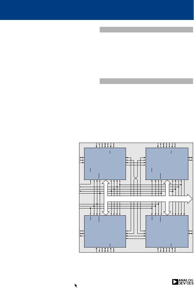
Quad-SHARCs AD14060/AD14160
480-MFLOP, Single Package Multiprocessor
The AD14060 Quad-SHARC is a first genera- |
|
Applications |
|
|
|
|
|
||||
tion (CQFP) DSP multiprocessor. Using high- |
Multi-SHARC designs with tight area/volume |
||||||||||
density packaging techniques, the module fits |
|||||||||||
constraints, such as large array and image |
|||||||||||
four SHARCs in approximately 30% of the |
|||||||||||
processors, smart missiles, avionics, and others |
|||||||||||
space required using discrete packages. |
|
||||||||||
|
will benefit. The AD14060/AD14160 are |
||||||||||
|
|
||||||||||
The AD14160 Quad-SHARC Ceramic Ball |
available as both industrial and MIL-SMD |
||||||||||
grade parts in 5V (AD14060/AD14160) or |
|||||||||||
Grid Array (CBGA) puts the power of the first |
|||||||||||
3.3V (AD14060L/AD14160L) versions. |
|
||||||||||
generation AD14060 (CQFP) DSP multiproces- |
|
||||||||||
|
|
|
|
|
|
|
|
|
|||
sor into a very high density ball grid array |
|
Competition |
|
|
|
|
|
||||
package, the module fits four SHARCs in |
|
|
|
|
|
|
|||||
With 480 MFLOPS of throughput, the |
|
|
|||||||||
approximately 30% of the space required using |
|
|
|||||||||
AD14060/AD14160 have no competition. TI's |
|||||||||||
discrete packages; now with additional link and |
|||||||||||
Dual C40 MCM provides a similar function, |
|||||||||||
serial I/O pinned out, beyond that from the |
|||||||||||
but delivers only 80 MFLOPS in a significantly |
|||||||||||
CQFP package. |
|
||||||||||
|
larger package, and roughly equivalent cost. |
||||||||||
|
|
||||||||||
The core of the multiprocessors is the |
|
The Quad-SHARC AD14060/AD14160 is tar- |
|||||||||
ADSP-21060 DSP Microcomputer. The |
|
geted to be priced such that users can take |
|||||||||
AD14060/ AD14160 modules have the highest |
advantage of system cost advantages of using |
||||||||||
performance-density and lowest cost-perfor- |
MCMs. |
|
|
|
|
|
|
||||
mance ratios of any multiprocessors in |
|
|
|
|
|
|
|
|
|
|
|
their class. They are ideal for applica- |
|
CS TIMEXP |
2-0 |
2,0 |
|
|
CS TIMEXP LINK 1 LINK 3 |
2-0 |
2,0 |
|
|
tions requiring higher levels of perfor- |
|
|
|
|
|||||||
|
LINK1 LINK3 LINK4 IRQ |
FLAG |
|
|
LINK4 IRQ |
FLAG |
|
||||
mance and/or functionality per unit |
|
|
|
|
|||||||
CPA |
|
|
|
LINK 0 |
LINK 0 |
|
|
|
CPA |
||
SPORT 1 |
SHARC_A |
|
LINK 2 |
LINK 2 |
|
|
|
SPORT 1 |
|||
area. |
|
SHARC_B |
|
||||||||
TDI |
|
LINK 5 |
LINK 5 |
|
|
||||||
|
ID2-0 = 1 |
|
TDO |
TDI |
ID2-0 |
= 2 |
|
|
|||
|
|
|
|
|
|
|
|||||
The AD14060/AD14160 take advan- |
|
|
|
1 |
3 |
|
|
|
1 |
3 |
|
EBOOT, LBOOT,BMS |
EMU CLKIN RESET |
SPORT 0 |
TCK, TMS,TRST FLAG |
FLAG |
EBOOT, LBOOT,BMS |
EMU CLKIN RESET |
SPORT 0 |
TCK, TMS,TRST FLAG |
FLAG TDO |
||
tage of the built-in multiprocessing |
|||||||||||
|
|
|
|
|
|
|
|
|
|
||
features of the ADSP-21060, to |
|
|
|
|
|
|
|
|
|
|
|
achieve 480 peak MFLOPS with a sin- |
|
|
|
|
|
|
|
|
|
|
|
gle chip type, in a single package. The |
AD14060/ |
|
|
|
|
(ADDR31-0, DATA47-0, MS3-0, RD, WR, PAGE, ADRCLK, SW, ACK, |
|||||
on-chip SRAM of the DSPs provides |
AD14060L |
|
SHARC BUS SBTS, HBR, HBG, REDY, BR6-1, RPBA, DMAR1-2, DMAG1-2) |
|
|||||||
|
|
|
|
|
|
|
|
|
|
||
16 Mbits of on-module shared SRAM. |
|
|
|
|
|
|
|
|
|
|
|
The complete shared bus (48-bit data, |
|
|
|
1 |
3 |
|
|
|
1 |
3 |
|
32-address) is also brought off-module |
|
|
|
|
|
|
|||||
EBOOT, LBOOT,BMS |
EMU CLKIN RESET |
SPORT0 |
TCK, TMS,TRST FLAG |
FLAG |
EBOOT, LBOOT,BMS |
EMU CLKIN RESET |
SPORT0 |
TCK, TMS,TRST FLAG |
FLAG TDO |
||
for interfacing with expansion memo- |
|||||||||||
ry and/or other peripherals. |
|||||||||||
CPA |
SHARC_D |
|
LINK 0 |
LINK 0 |
SHARC_C |
|
CPA |
||||
SPORT 1 |
|
LINK 2 |
LINK 2 |
|
SPORT 1 |
||||||
|
ID2-0 = 4 |
|
ID2-0 = 3 |
|
|||||||
|
TDO |
|
LINK 5 |
LINK 5 |
|
|
|||||
|
|
CS TIMEXP |
|
2,0 |
TDI |
TDO |
CS TIMEXP LINK 1 LINK 3 |
|
2,0 |
|
|
|
|
0 |
|
|
0 |
|
|||||
|
|
-2 |
FLAG |
|
|
-2 |
FLAG |
|
|||
|
|
LINK1 LINK3 LINK4 IRQ |
|
|
LINK4 IRQ |
|
|||||
AD14060 Functional Block Diagram
46 DSP Selection Guide |
http://www.analog.com/milsystems |
|
|
|

Quad-SHARCs AD14060/AD14160
Development Tools
Both the AD14060 and AD14160 are supported with a complete set of software and hardware development tools, including an ADSP-21061 EZ-KIT Lite, and development software.
Features
•ADSP-21060 core processor (. . . x4)
•480 MFLOPS Peak, 320 MFLOPS sustained
•25 ns instruction rate, single-cycle instruction execution - each of 4 processors
•16 Mbit shared SRAM (internal to SHARC’s)
•4 gigawords addressable off - module memory
•48-bit shared memory bus, 48-bit data bus
•Full 32-bit address bus
•Interrupts, flag pins, and timers are also avail able as I/O
•32-Bit single precision and 40-Bit extended precision IEEE floating-point data formats, or 32-Bit fixed-point data format
•User configurable boot modes, bus priority, and other features with control lines
•IEEE JTAG standard 1149.1 test access port and on-chip emulation
AD14060
–T welve 40 Mbyte/s link ports (3 per SHARC) accessible to/from the outside world
–Four link ports connected internally in a ring configuration
–Four 40 Mbit/s independent serial ports (one from each SHARC)
–One 40 Mbit/s common serial port
–Ceramic quad flat pack with enhanced I/O
–Low-profile 2.05” 308 lead ceramic quad flat pack package
AD14160
–Sixteen 40 Mbyte/s link ports (per SHARC) accessible to/from the outside world
–Eight link ports connected internally in ring configuration
–Eight 40 Mbit/s independent serial ports (two from each SHARC) available from outside
–Ceramic ball grid array QUAD-SHARC with enhanced I/O
–Low-profile 1.85" ceramic ball grid array package
For any further inquiries, please contact MCP Marketing in Greensboro, NC at 336-668-9511
http://www.analog.com/milsystems
|
|
http://www.analog.com/milsystems |
DSP Selection Guide 47 |
|
Software and Systems Technologies (SST)
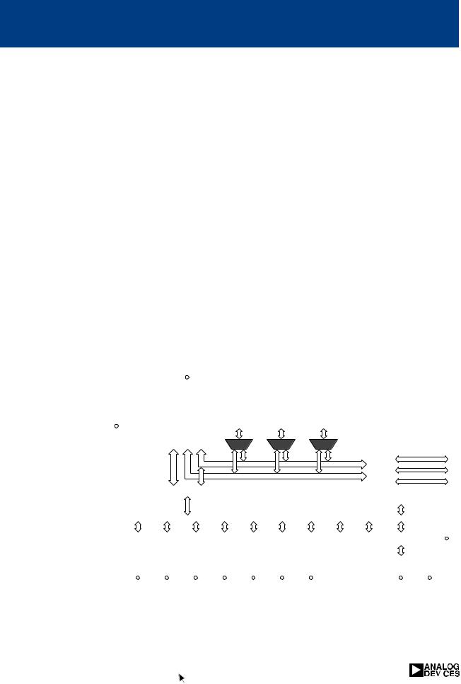
Marketplace pressures of the newest technologies, faster time to market, and ever-lower systems costs drive leading OEMs to look for the newest, fastest ways to introduce their products to their customers.
To meet this need, Analog Devices Inc. offers numerous chipset and algorithm reference designs and third party support in emerging and high growth market segments.
SST-Melody-32
For High Volume Multi-Channel Digital Audio Processing
Features |
Reference Block Diagram |
|
• 32-bit implementation of industry standard |
|
|
|
|
|
|
|
|
|
|
|
|
|
|
|
|
|
|
|
|
|
|
|
|
|
|
|
|
|
|
|
|
|
|
|
|
|
|
|
|
|
|
|
|
|
|
|
|
|
|
|
|
||
|
|
|
|
|
|
|
|
|
|
|
|
|
|
|
|
|
|
|
|
|
|
|
|
|
|
||
|
audio formats on new DSP platform |
|
|
|
|
|
|
|
|
|
|
|
|
|
|
|
|
|
|
|
|
|
|
|
|
|
|
|
|
|
S/PDIF Rx |
|
|
Codec |
|
|
Host |
|
|
|
|||||||||||||||
|
• Decodes up to 8 channels of multiplexed |
|
|
|
|
(AD 183x) |
|
|
|
|
|||||||||||||||||
|
|
|
|
|
|
|
|
|
|
|
|
|
|
|
|
|
|
||||||||||
|
|
|
|
|
|
|
|
|
|
|
|
|
|
|
|
|
|
|
|
|
|
|
|
|
|
||
|
audio: scaleable between 1 and 8 channels, |
|
|
|
|
|
|
|
|
|
|
|
|
|
|
|
|
|
|
|
|
|
SPI Bus |
||||
|
|
|
|
|
|
|
|
|
|
|
|
|
|
|
|
|
|
|
|||||||||
|
|
|
|
|
|
|
|
|
|
|
|
|
|
|
|
|
|
|
|
|
|
|
|
|
|
||
|
with 6.1 core channels and 2 extended channels |
|
|
|
|
|
|
|
|
|
|
|
|
|
|
|
|
|
|
|
|
|
|
|
|
|
|
|
|
|
|
|
|
|
|
|
|
|
|
|
|
|
|
|
|
|
|
|
|
|
|
|
|
||
|
|
|
|
|
|
|
|
|
|
|
|
|
|
|
|
|
|
|
|
|
|
|
|
|
|
||
|
• Sufficient computing power for custom OEM |
|
|
|
|
|
|
|
|
|
|
|
|
|
|
|
|
|
|
|
|
|
|
|
|
|
|
|
|
|
|
|
|
|
|
|
|
|
|
|
|
|
|
|
|
|
|
|
SRAM |
|
|
|
|||
|
applications such as speaker equalizers and |
|
|
|
|
|
|
|
Melody 32 |
|
|
|
|
|
|
|
|||||||||||
|
|
|
|
|
|
|
|
|
|
|
|
|
|
|
|
||||||||||||
|
|
|
|
|
|
|
|
|
|
|
|
|
|
|
|
|
|
||||||||||
|
surround fields |
|
|
|
|
|
|
|
|
|
|
|
|
|
|
|
|
|
|
|
|
64kx16, 20 ns. |
|
||||
|
|
|
|
|
|
|
|
|
|
|
|
|
|
|
|
|
|
|
|
|
|
Not required |
|
||||
|
|
|
|
|
|
|
|
|
|
|
|
|
|
|
|
|
|
|
|
|
|
For 5.1 models |
|
||||
|
Benefits |
|
|
|
|
|
|
|
|
|
|
|
|
|
|
|
|
|
|
|
|||||||
|
|
|
|
|
|
|
|
|
|
|
|
|
|
|
|
|
|
|
|
|
|
|
|
|
|
|
|
|
|
|
|
|
|
|
|
|
|
|
|
|
|
|
|
|
|
|
|
|
|
|
|
|
|
|
|
|
• Melody 32 offers end-to-end 32-bit precision of |
|
|
|
|
|
|
|
|
|
|
|
|
|
|
|
|
|
|
|
|
|
|
|
|
|
|
|
|
|
|
|
|
|
|
Boot Flash |
|
|
|
|
|
|
|
|
|||||||||||
|
decode & post-processing for leading digital |
|
|
|
|
|
|
|
|
|
|
|
|
|
|
|
|
|
|
|
|
|
|
|
|
|
|
|
|
|
|
|
|
512kx8, 100 ns. |
|
|
|
|
|
|
|
||||||||||||||
|
audio formats in real-time. |
|
|
|
|
|
|
|
|
|
|
|
|
|
|||||||||||||
|
|
|
|
|
|
|
|
|
|
|
|
|
|
|
|
|
|
|
|
|
|
|
|
|
|
|
|
|
|
|
|
|
|
|
|
|
|
|
|
|
|
|
|
|
|
|
|
|
|
|
|
|
|
|
|
|
• The Melody reference design decodes up to 7.1 |
|
|
|
|
|
|
|
|
|
|
|
|
|
|
|
|
|
|
|
|
|
|
|
|
|
|
|
|
Chipsets |
|
|
|
|
|
|
|
|
|
|
|
|
|
|
|
|
|
||||||||
|
channels of DTS ES Extended Surround, Dolby |
|
|
|
|
|
|
|
|
|
|
|
|
|
|
|
|
|
|
||||||||
|
|
ADSST-MEL-20: Bundled chipset that includes the |
|||||||||||||||||||||||||
|
Digital, Dolby Pro Logic II, AAC, MP3, and |
|
|||||||||||||||||||||||||
|
|
high performance of the ADSST-MEL322 processor |
|||||||||||||||||||||||||
|
includes THX Surround EX, Bass Management, |
|
|||||||||||||||||||||||||
|
|
with a high performance audio codec. It includes |
|||||||||||||||||||||||||
|
Delay Management, and automatic detection of |
|
|||||||||||||||||||||||||
|
|
decoding / post processing for Dolby Digital EX, |
|||||||||||||||||||||||||
|
the incoming audio bit-stream. |
|
|
||||||||||||||||||||||||
|
|
|
Dolby Pro Logic II, AAC (LC), DTS ES (Discrete |
||||||||||||||||||||||||
|
• Decoder supports all bit rates (up to 1,536 kbps), |
|
|||||||||||||||||||||||||
|
|
and Matrix), DTS Neo:6. |
|
|
|
|
|
|
|
||||||||||||||||||
|
compression ratios (up to 40:1) and sampling |
|
|
|
|
|
|
|
|
||||||||||||||||||
|
|
ADSST-MEL-30: Includes decoding / post process- |
|||||||||||||||||||||||||
|
frequencies (32, 44.1, and 48 kHz per channel) |
|
|||||||||||||||||||||||||
|
|
ing for Dolby Digital EX, Dolby Pro Logic II, DTS ES |
|||||||||||||||||||||||||
|
specified by the DTS (Digital Theater Systems) |
|
|||||||||||||||||||||||||
|
|
(Discrete and Matrix), DTS Neo:6, THX EX, SRS |
|||||||||||||||||||||||||
|
and Dolby audio standards. It also supports fea |
|
|||||||||||||||||||||||||
|
|
Circle Surround II, TruBass codes. The chipset |
|||||||||||||||||||||||||
|
tures specified by the DTS standard -- including |
|
|||||||||||||||||||||||||
|
|
includes ADI Surround modes, Speaker EQ as well |
|||||||||||||||||||||||||
|
Dynamic Range Control, Down-Mixing, and Re- |
|
as Bass Management and Delay. |
||||||||||||||||||||||||
|
equalization of all channels independently. |
|
ADSST-MEL-40: Features of the ADSST-MEL-30 |
||||||||||||||||||||||||
|
|
|
|
||||||||||||||||||||||||
|
|
|
|
but without THX processing. |
|
|
|
|
|
|
|
||||||||||||||||
|
Applications |
|
|
|
|
|
|
|
|
||||||||||||||||||
|
|
|
ADSST-MEL-50: Includes decoding / post process- |
||||||||||||||||||||||||
|
• Home theater AVR systems |
|
|
||||||||||||||||||||||||
|
|
|
ing for Dolby Digital EX, Dolby Pro Logic II, DTS ES |
||||||||||||||||||||||||
|
• Automotive audio |
|
|
||||||||||||||||||||||||
|
|
|
(Discrete and Matrix), DTS Neo:6 and SRS Circle |
||||||||||||||||||||||||
|
• DVD players |
|
|
||||||||||||||||||||||||
|
|
|
Surround II codes. The chipset includes |
||||||||||||||||||||||||
|
• Video game consoles |
|
|
||||||||||||||||||||||||
|
|
|
Wavesurround Headphone and Loudspeaker |
||||||||||||||||||||||||
|
• Set Top boxes |
|
|
||||||||||||||||||||||||
|
|
|
Virtualizer modes, Bass Management and Delay. |
||||||||||||||||||||||||
|
|
|
|
||||||||||||||||||||||||
48 DSP Selection Guide |
|
|
|
|
|
|
|
|
|
|
|
|
|
|
|
|
|
|
|
|
|
|
|
|
|
||
http://www.analog.com/solutions |
|
|
|
|
|
|
|
|
|
|
|
|
|
|
|
|
|
|
|
|
|
|
|||||
|
|
|
|
|
|
|
|
|
|
|
|
|
|
|
|
|
|||||||||||
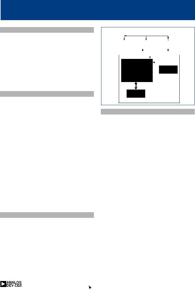
SST-Melody-SU
Highest Performance Multi-Channel Audio Processing
Features
•32-Bit floating-point implementation for decoding the leading encoded audio content .
•Decoders operate in real-time with the ability to auto-detect and display bit stream information
•D ecoders support all of the bit rates (up to 6,144 kbps) and sampling frequencies (32, 44.1, 48, 88.2, 96 and 192 kHz per channel) specified by the encoding standards
Benefits
•This enables OEMs to produce high-quality, low-cost designs featuring decoder algorithms and post processors for :
–DTS-ES Extended Surround (including both DTS ES Discrete 6.1 and DTS ES Matrix 6.1)
–DTS 96/24
–DTS Neo:6
–Dolby Digital, Dolby Pro Logic II, Dolby Headphone
–THX, THX Surround EX, THX Ultra2
–HDCD
–MPEG1 Audio Layer III (also known as MP3)
–MPEG AAC (both MP and LC versions)
–SRS Circle Surround II, SRS 3D Sound, SRS TruSurround, SRS Focus and SRS TruBass
–MLP
Applications
•Multi-channel audio decoders and postprocessors for digital audio designs using DSPs (Digital Signal Processors) in home theater
•Automotive audio receivers
•DVD players
Reference Block Diagram
S/PDIF Rx |
|
Codec |
|
Host |
|
||||||
|
(AD 183x) |
|
|
||||||||
|
|
|
|
|
|
|
|
||||
|
|
|
|
|
|
|
|
|
|
SPI Bus |
|
|
|
|
|
|
|
|
|
|
|
||
|
|
|
|
|
|
|
|
||||
|
|
|
|
|
|
|
|
|
|
|
|
|
|
|
|
|
|
|
|
|
|
|
|
|
|
|
|
|
|
|
|
|
|
|
|
MelodyTM
SHARC 
 SDRAM Ultra
1Mx16, 100 MHz (2 x 512k*32)
Boot Flash
1Mx8, 100 ns.
Models
Model ADSST-AUDIO-7060: is a twin combination chipset and includes decoding/post-processing for Dolby Digital, Dolby Pro Logic II, DTS, THX, DTS ES-Matrix, Bass Management and Delay.
Model ADSST-AUDIO-7070: Includes Dolby Digital and Dolby Pro Logic codes.
Model ADSST-AUDIO-7075: includes Dolby Digital, Dolby Pro Logic and DTS 5.1 codes.
Model ADSST-AUDIO-7085: Includes Dolby Digital, Dolby Pro Logic II, DTS ES, DTS 6.1, DTS 96/24, DTS Neo:6, AAC LC and MP, THX Ultra2, Bass Management and Delay Management.
Model ADSST-AUDIO-7090: Includes Dolby Digital, DTS ES, DTS 6.1, DTS 96/24, MPEG2 BC, MPEG2 AAC LC and MP, Dolby Pro Logic II, DTS Neo:6.
Model ADSST-AUDIO 7095: Includes Dolby EX, DTS ES Matrix, Bass Management, THX Ultra2, Delay Management and Dolby Headphone.
|
http://www.analog.com/solutions |
DSP Selection Guide 49 |
|
|