

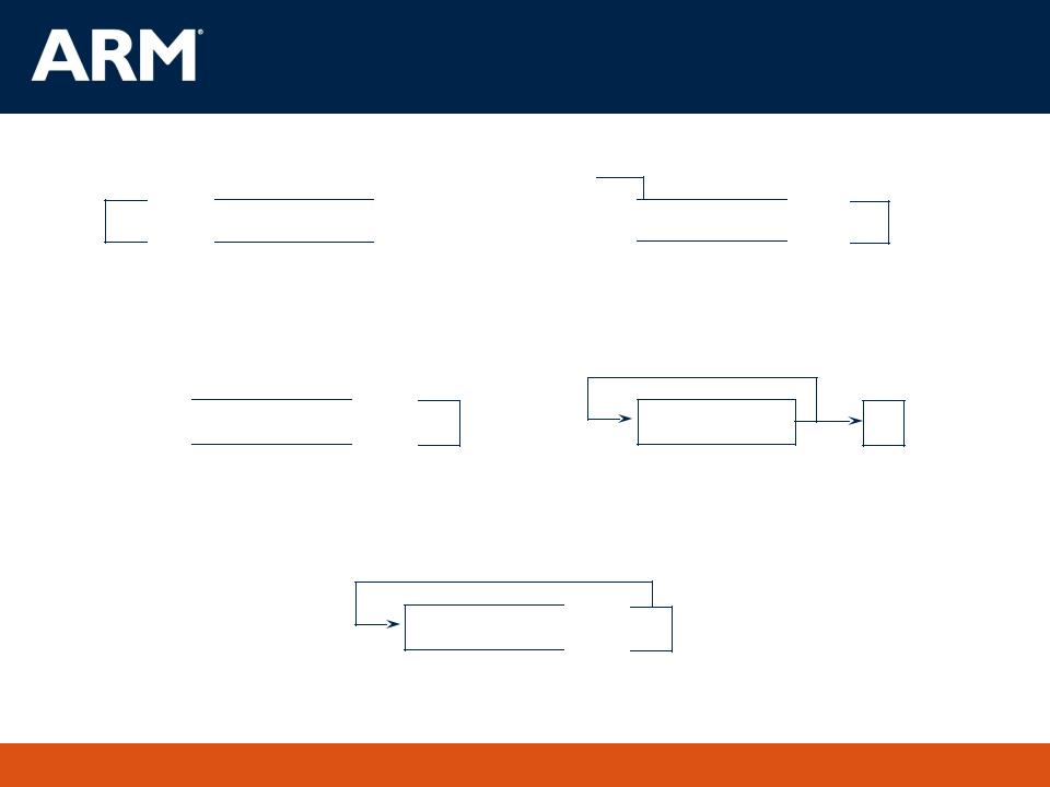
Branch instructions
|
Branch : |
B{<cond>} label |
|
Branch with Link : |
BL{<cond>} subroutine_label |
31 |
|
|
28 27 |
|
25 |
24 23 |
|
|
|
|
|
|
|
0 |
||||||||||||||||||
|
|
|
|
|
|
|
|
|
|
|
|
|
|
|
|
|
|
|
|
|
|
|
|
|
|
|
|
|
|
|
|
|
Cond |
|
1 0 |
1 |
L |
|
|
|
|
|
|
|
|
|
|
Offset |
|||||||||||||||||
|
|
|
|
|
|
|
|
|
|
|
|
|
|
|
|
|
|
|
|
|
|
|
|
|
|
|
|
|
|
|
|
|
|
|
|
|
|
|
|
|
|
|
|
Link bit 0 |
= Branch |
||||||||||||||||||||
|
|
|
|
|
|
|
|
|
|
|
||||||||||||||||||||||
|
|
|
|
|
|
|
|
|
|
|
||||||||||||||||||||||
|
|
|
|
|
|
|
1 |
= Branch with link |
||||||||||||||||||||||||
Condition field
The processor core shifts the offset field left by 2 positions, sign-extends it and adds it to the PC
± 32 Mbyte range
How to perform longer branches?
39v10 The ARM Architecture |
21 |

Data processing Instructions
Consist of : |
|
|
|
|
|
|
|
|
Arithmetic: |
ADD |
ADC |
SUB |
SBC |
RSB |
RSC |
|
Logical: |
AND |
ORR |
EOR |
BIC |
|
|
|
Comparisons: |
CMP |
CMN |
TST |
TEQ |
|
|
|
Data movement: |
MOV |
MVN |
|
|
|
|
These instructions only work on registers, NOT memory.
Syntax:
<Operation>{<cond>}{S} Rd, Rn, Operand2
Comparisons set flags only - they do not specify Rd
Data movement does not specify Rn
Second operand is sent to the ALU via barrel shifter.
39v10 The ARM Architecture |
22 |
LSL : Logical Left Shift
CF 

 Destination
 0
0
Multiplication by a power of 2
The Barrel Shifter
ASR: Arithmetic Right Shift


 Destination

 CF
CF
Division by a power of 2,
preserving the sign bit
LSR : Logical Shift Right
...0 
 Destination
 CF
CF
Division by a power of 2
ROR: Rotate Right
Destination |
CF |
Bit rotate with wrap around from LSB to MSB
RRX: Rotate Right Extended
Destination 
 CF
CF
Single bit rotate with wrap around from CF to MSB
39v10 The ARM Architecture |
23 |

Using the Barrel Shifter:
The Second Operand
Operand |
Operand |
1 |
2 |
Barrel
Shifter
ALU
Register, optionally with shift operation
Shift value can be either be:
5 bit unsigned integer
Specified in bottom byte of another register.
Used for multiplication by constant
Immediate value
8 bit number, with a range of 0-255.
Rotated right through even number of positions
Allows increased range of 32-bit constants to be loaded directly into registers
Result
39v10 The ARM Architecture |
24 |

Immediate constants (1)
No ARM instruction can contain a 32 bit immediate constant
All ARM instructions are fixed as 32 bits long
The data processing instruction format has 12 bits available for operand2
11 |
|
|
8 7 |
0 |
|||||||||
|
|
rot |
|
|
|
immed_8 |
|||||||
|
|
|
|
|
|
|
|
|
|
|
|
|
|
|
x2 |
|
|
|
|
|
|
|
|
|
|
|
|
|
|
|
|
|
|
|
|
|
|
|
|
||
|
|
|
|
Shifter |
|
||||||||
|
|
|
|
|
|
|
|
||||||
|
|
|
|
|
|
|
|
ROR |
|
||||
|
|
|
|
|
|
|
|
|
|
|
|
|
|
|
|
|
|
|
|
|
|
|
|
|
|
|
|
Quick Quiz:
0xe3a004ff MOV r0, #???
4 bit rotate value (0-15) is multiplied by two to give range 0-30 in steps of 2
Rule to remember is “8-bits shifted by an even number of bit positions”.
39v10 The ARM Architecture |
25 |

Immediate constants (2)
Examples:
31 |
0 |
ror #0
ror #8
ror #30
0 |
0 |
0 |
0 |
0 |
0 |
0 |
0 |
0 |
0 |
0 |
0 |
0 |
0 |
0 |
0 |
0 |
0 |
0 |
0 |
0 |
0 |
0 |
0 |
|
|
|
|
|
|
|
|
|
range 0-0x000000ff step 0x00000001 |
|
|
|
|
|
|
|
|
|
|
|
|
|
|
|
|
|
|
|
|
|
|
|
|
|
|
|
|
|
|
|
|
|
|
|
|
|
|
|
|
|
|
0 |
0 |
0 |
0 |
0 |
0 |
0 |
0 |
0 |
0 |
0 |
0 |
0 |
0 |
0 |
0 |
0 |
0 |
0 |
0 |
0 |
0 |
0 |
0 |
|
range 0-0xff000000 step 0x01000000 |
|
|
|
|
|
|
|
|
|
|
|
|
|
|
|
|
|
|
|
|
|
|
|
|
|
|
|
|
|
|||||
0 |
0 |
0 |
0 |
0 |
0 |
0 |
0 |
0 |
0 |
0 |
0 |
0 |
0 |
0 |
0 |
0 |
0 |
0 |
0 |
0 |
0 |
|
|
|
|
|
|
|
|
0 |
0 |
|
range 0-0x000003fc step 0x00000004 |
The assembler converts immediate values to the rotate form:
MOV r0,#4096 ; uses 0x40 ror 26
ADD r1,r2,#0xFF0000 ; uses 0xFF ror 16
The bitwise complements can also be formed using MVN:
MOV r0, #0xFFFFFFFF |
; assembles to MVN r0,#0 |
Values that cannot be generated in this way will cause an error.
39v10 The ARM Architecture |
26 |

Loading 32 bit constants
To allow larger constants to be loaded, the assembler offers a pseudo- instruction:
LDR rd, =const
This will either:
Produce a MOV or MVN instruction to generate the value (if possible).
or
Generate a LDR instruction with a PC-relative address to read the constant from a literal pool (Constant data area embedded in the code).
For example
|
LDR |
r0,=0xFF |
=> |
MOV r0,#0xFF |
|
LDR |
r0,=0x55555555 |
=> |
LDR r0,[PC,#Imm12] |
|
|
|
|
… |
|
|
|
|
… |
|
|
|
|
DCD 0x55555555 |
This is the recommended way of loading constants into a register
39v10 The ARM Architecture |
27 |

Multiply
Syntax:
|
MUL{<cond>}{S} Rd, Rm, Rs |
Rd = Rm * Rs |
|
MLA{<cond>}{S} Rd,Rm,Rs,Rn |
Rd = (Rm * Rs) + Rn |
|
[U|S]MULL{<cond>}{S} RdLo, RdHi, Rm, Rs |
RdHi,RdLo := Rm*Rs |
|
[U|S]MLAL{<cond>}{S} RdLo, RdHi, Rm, Rs |
RdHi,RdLo := (Rm*Rs)+RdHi,RdLo |
Cycle time
Basic MUL instruction
2-5 cycles on ARM7TDMI
1-3 cycles on StrongARM/XScale
2 cycles on ARM9E/ARM102xE
+1 cycle for ARM9TDMI (over ARM7TDMI)
+1 cycle for accumulate (not on 9E though result delay is one cycle longer)
+1 cycle for “long”
Above are “general rules” - refer to the TRM for the core you are using for the exact details
39v10 The ARM Architecture |
28 |

Single register data transfer
LDR |
STR |
Word |
LDRB |
STRB |
Byte |
LDRH |
STRH |
Halfword |
LDRSB |
|
Signed byte load |
LDRSH |
|
Signed halfword load |
Memory system must support all access sizes
Syntax:
LDR{<cond>}{<size>} Rd, <address>
STR{<cond>}{<size>} Rd, <address>
e.g. LDREQB
39v10 The ARM Architecture |
29 |

Address accessed
Address accessed by LDR/STR is specified by a base register plus an offset
For word and unsigned byte accesses, offset can be
An unsigned 12-bit immediate value (ie 0 - 4095 bytes).
LDR r0,[r1,#8]
A register, optionally shifted by an immediate value
LDR r0,[r1,r2]
LDR r0,[r1,r2,LSL#2]
This can be either added or subtracted from the base register:
LDR r0,[r1,#-8]
LDR r0,[r1,-r2]
LDR r0,[r1,-r2,LSL#2]
For halfword and signed halfword / byte, offset can be:
An unsigned 8 bit immediate value (ie 0-255 bytes).
A register (unshifted).
Choice of pre-indexed or post-indexed addressing
39v10 The ARM Architecture |
30 |