
Добавил:
Upload
Опубликованный материал нарушает ваши авторские права? Сообщите нам.
Вуз:
Предмет:
Файл:S5000PSL.pdf
X
- •1. Introduction
- •1.1 Chapter Outline
- •1.2 Server Board Use Disclaimer
- •2. Server Board Overview
- •2.1 Server Board Feature Set
- •2.2 Server Board Layout
- •2.2.1 Server Board Connector and Component Layout
- •2.2.2 Server Board Mechanical Drawings
- •2.2.3 Server Board ATX I/O Layout
- •3. Functional Architecture
- •3.1.1 System Bus Interface
- •3.1.2 Processor Support
- •3.1.2.1 Processor Population Rules
- •3.1.2.2 Common Enabling Kit (CEK) Design Support
- •3.1.3 Memory Subsystem
- •3.1.3.1 Memory RASUM Features
- •3.1.3.2 Supported Memory
- •3.1.3.3 DIMM Population Rules and Supported DIMM Configurations
- •3.1.3.4.1 Mirrored Mode Memory Configuration
- •3.1.3.4.2 Sparing Mode Memory Configuration
- •3.1.3.4.2.1 Single Branch Mode Sparing
- •3.1.3.4.2.2 Dual Branch Mode Sparing
- •3.1.4 Snoop Filter (5000X MCH only)
- •3.2.1 PCI Subsystem
- •3.2.1.3 PE0: One x4 PCI Express* Bus Segment
- •3.2.1.4 PE1: One x4 PCI Express* Bus Segment
- •3.2.1.5 PE2: One x4 PCI Express* Bus Segment
- •3.2.1.6 PE4, PE5: Two x4 PCI Express* Bus Segments
- •3.2.1.7 PE6, PE7: Two x4 PCI Express* Bus Segments
- •3.2.1.8 PCI Express* Riser Slot
- •3.2.2 Serial ATA Support
- •3.2.2.2 Intel® Embedded Server RAID Technology Option ROM
- •3.2.3 Parallel ATA (PATA) Support
- •3.2.4 USB 2.0 Support
- •3.3 Video Support
- •3.3.1 Video Modes
- •3.3.2 Video Memory Interface
- •3.3.3 Dual Video
- •3.4 SAS Controller
- •3.4.1 SAS RAID Support
- •3.4.2 SAS/SATA Connector Sharing
- •3.5 Network Interface Controller (NIC)
- •3.5.2 MAC Address Definition
- •3.6 Super I/O
- •3.6.1 Serial Ports
- •3.6.2 Floppy Disk Controller
- •3.6.3 Keyboard and Mouse Support
- •3.6.5 System Health Support
- •4. Platform Management
- •5. Connector/Header Locations and Pin-outs
- •5.1 Board Connector Information
- •5.2 Power Connectors
- •5.3 System Management Headers
- •5.3.2 LCP/AUX IPMB Header
- •5.3.3 IPMB Header
- •5.3.4 HSBP Header
- •5.3.5 SGPIO Header
- •5.3.7 HDD Activity LED Header
- •5.4 Front Panel Connector
- •5.5 I/O Connectors
- •5.5.1 VGA Connector
- •5.5.2 NIC Connectors
- •5.5.3 IDE Connector
- •5.5.5 SATA/SAS Connectors
- •5.5.6 Serial Port Connectors
- •5.5.7 Keyboard and Mouse Connector
- •5.5.8 USB Connector
- •5.6 Fan Headers
- •6. Jumper Blocks
- •6.1 CMOS Clear and Password Reset Usage Procedure
- •6.1.1 Clearing the CMOS
- •6.1.2 Clearing the Password
- •6.2 BMC Force Update Procedure
- •6.3 BIOS Select Jumper
- •7. Intel® Light-Guided Diagnostics
- •7.2 Fan Fault LEDs
- •7.3 System ID LED and System Status LED
- •7.3.1 System Status LED – BMC Initialization
- •7.4 DIMM Fault LEDs
- •7.5 Processor Fault LEDs
- •7.6 Post Code Diagnostic LEDs
- •8. Design and Environmental Specifications
- •8.3 Server Board Power Requirements
- •8.3.1 Processor Power Support
- •8.4.1 Grounding
- •8.4.2 Standby Outputs
- •8.4.3 Remote Sense
- •8.4.4 Voltage Regulation
- •8.4.5 Dynamic Loading
- •8.4.6 Capacitive Loading
- •8.4.7 Ripple/Noise
- •8.4.8 Timing Requirements
- •8.4.9 Residual Voltage Immunity in Standby Mode
- •9. Regulatory and Certification Information
- •9.1 Product Regulatory Compliance
- •9.1.1 Product Safety Compliance
- •9.1.2 Product EMC Compliance – Class A Compliance
- •9.1.3 Certifications/Registrations/Declarations
- •9.2 Product Regulatory Compliance Markings
- •9.3 Electromagnetic Compatibility Notices
- •9.3.1 FCC Verification Statement (USA)
- •9.3.3 Europe (CE Declaration of Conformity)
- •9.3.4 VCCI (Japan)
- •9.3.5 BSMI (Taiwan)
- •9.3.6 RRL (Korea)
- •9.4 Restriction of Hazardous Substances (RoHS) Compliance
- •Appendix A: Integration and Usage Tips
- •Appendix B: BMC Sensor Tables
- •Appendix C: POST Code Diagnostic LED Decoder
- •Appendix D: POST Code Errors
- •Appendix E: Supported Intel® Server Chassis
- •Glossary
- •Reference Documents

Intel® Server Boards S5000PSL and S5000XSL TPS |
Server Board Overview |
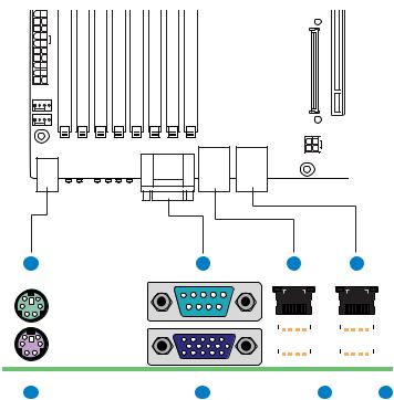
2.2.3Server Board ATX I/O Layout
The following figure shows the layout of the rear I/O components for the server board.
A C E G
|
|
|
|
|
|
|
|
|
|
|
|
|
|
|
|
|
|
|
|
|
|
|
|
|
|
|
|
|
|
|
|
|
|
|
|
|
|
|
|
|
|
|
|
|
|
|
|
|
|
|
|
|
|
|
|
|
|
|
|
|
|
|
|
|
|
|
|
|
|
|
|
|
|
|
|
|
|
|
|
|
|
|
|
|
|
|
|
|
|
|
|
|
|
|
|
|
|
|
|
|
|
|
|
|
|
|
|
|
|
|
|
|
|
|
|
|
|
|
|
|
|
|
|
|
|
|
|
|
|
|
|
|
|
|
|
|
|
|
|
|
|
|
|
|
|
|
|
|
|
|
|
|
|
|
|
|
|
|
|
|
|
|
|
|
|
|
|
|
|
|
|
|
|
|
|
|
|
|
|
|
|
|
|
|
|
|
|
|
|
|
|
|
|
|
|
|
|
|
|
|
|
|
|
|
|
|
|
|
|
|
|
|
|
|
|
|
|
|
|
|
|
|
|
|
|
|
|
|
|
B |
D |
F |
H |
|||||||||||||
|
|
|
|
|
|
|
|
|
|
|
|
|
AF000222 |
|||||
|
|
|
|
|
|
|
|
|
|
|
||||||||
A. PS/2 mouse |
E. NIC port 1 (1 Gb) |
|
|
|
|
|
|
|
|
|
||||||||
|
|
|
|
|
||||||||||||||
B. PS/2 keyboard |
F. USB port 2 (top), 3 (bottom) |
|
|
|
||||||||||||||
|
|
|
|
|
|
|
|
|
|
|
||||||||
C. Serial port |
G. NIC port 2 (1 Gb) |
|
|
|
|
|
|
|
|
|
||||||||
|
|
|
|
|
||||||||||||||
D. Video |
H. USB port 0 (top), 1 (bottom) |
|
|
|
||||||||||||||
|
|
|
|
|
|
|
|
|
|
|
|
|
|
|
|
|
|
|
Figure 9. ATX I/O Layout
Revision 1.7 |
13 |
|
|
|
Intel order number: D41763-008 |
Соседние файлы в предмете [НЕСОРТИРОВАННОЕ]