

Server Board Overview |
Intel® Server Boards S5000PSL and S5000XSL TPS |
2.2Server Board Layout
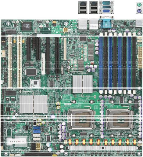
Figure 1. Server Board Photograph
2.2.1Server Board Connector and Component Layout
The following figure shows the board layout of the server board. Each connector and major component is identified by a letter. A table of component descriptions follows the figure.
4 |
Revision 1.7 |
|
|
|
Intel order number: D41763-008 |

Intel® Server Boards S5000PSL and S5000XSL TPS |
Server Board Overview |
Figure 2. Board Layout
Revision 1.7 |
5 |
|
|
|
Intel order number: D41763-008 |
||
|
Server Board Overview |
|
Intel® Server Boards S5000PSL and S5000XSL TPS |
|
|
|
Table 2. Major Board Components |
||
|
|
|
|
|
|
|
Description |
|
Description |
|
A |
PCI-X 64-bit, 100-MHz slot 1 |
X |
IPMB connector |
|
|
|
|
|
|
B |
PCI-X 64-bit, 133-/100-MHz slot 2 |
Y |
System fan 2 header |
|
|
|
|
|
|
C |
PCI Express* x4[1]/or PCI Express* x8[2] slot 3 |
Z |
System fan 1 header |
|
|
(x8 physical connector) |
|
|
|
|
|
|
|
|
D |
RMM/RMM2 NIC connector |
AA |
Processor power connector |
|
|
|
|
|
|
E |
PCI Express* x4 slot 4 (x8 physical connector, |
BB |
USB header |
|
|
ROMB Slot) |
|
|
|
|
|
|
|
|
F |
PCI Express* x8 slot 5 (x16 physical connector) |
CC |
IDE connector |
|
|
|
|
|
|
G |
PCI Express* x8 slot 6 (x16 physical connector) |
DD |
Enclosure management SATA SGPIO header[2] |
|
H |
CMOS battery |
EE |
Intel® Local Control Panel header |
|
I |
P12V4 connector |
FF |
Hot-swap backplane B header |
|
|
|
|
|
|
J |
Connector for Intel® Remote Management |
GG |
Enclosure management SAS SES I2C [1] |
|
|
Module or Intel® Remote Management Module 2 |
|
|
|
K |
Back panel I/O ports |
HH |
Hot-swap backplane A header |
|
|
|
|
|
|
L |
Diagnostic and identification LEDs |
II |
SATA 0 |
|
M |
System fan 6 header |
JJ |
SATA 1 |
|
|
|
|
|
|
N |
System fan 5 header |
KK |
SATA 2 or SAS 0[3] |
|
O |
Main power connector |
LL |
SATA 3 or SAS 1[3] |
|
P |
Auxilliary power signal connector |
MM |
SATA 4 or SAS 2[3] |
|
Q |
DIMM sockets |
NN |
SATA 5 or SAS 3[3] |
|
R |
Processor 1 socket |
OO |
USB port |
|
|
|
|
|
|
S |
Processor 2 socket |
PP |
Front control panel header |
|
|
|
|
|
|
T |
Processor 2 fan header |
SATA Software RAID 5 Activation Key connector [2] |
|
|
U |
Processor 1 fan header |
RR |
SAS Software RAID 5 Activation Key connector [1] |
|
V |
System fan 4 header |
SS |
Serial B/emergency management port header |
|
|
|
|
|
|
W |
System fan 3 header |
TT |
Chassis intrusion header |
|
|
|
|
|
Notes:
1.Available with product codes S5000PSLSAS/S5000PSLSASR and BB5000PSLSAS/BB5000XSLSASR.
2.Available with product codes S5000PSLSATA/S5000PSLSATAR, S5000PSLSROMB/S5000PSLROMBR, BB5000PSLSATA/BB5000PSLSATAR, BB5000PSLROMB/BB5000PSLROMBR, and BB5000XSLSATA/BB5000XSLSATAR.
3.SAS connector available with product codes S5000PSLSAS/S5000PSLSASR and BB5000PSLSAS/BB5000XSLSASR.
6 |
Revision 1.7 |
|
|
|
Intel order number: D41763-008 |
Intel® Server Boards S5000PSL and S5000XSL TPS |
Server Board Overview |
2.2.2Server Board Mechanical Drawings
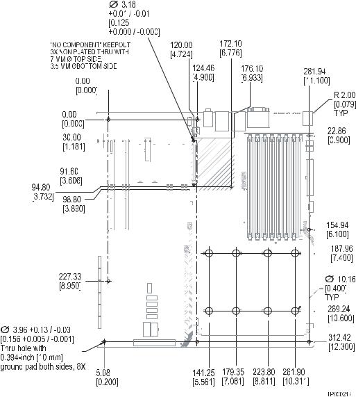
Figure 3. Mounting Hole Positions
Revision 1.7 |
7 |
|
|
|
Intel order number: D41763-008 |
||
Server Board Overview |
Intel® Server Boards S5000PSL and S5000XSL TPS |
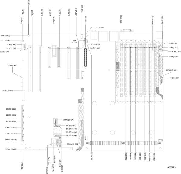
Figure 4. Component Positions
8 |
Revision 1.7 |
|
|
|
Intel order number: D41763-008 |
Intel® Server Boards S5000PSL and S5000XSL TPS |
Server Board Overview |
18.72 [ 0.737 ]
TYP
301.50 [ 11.870 ]
TYP
|
|
|
|
|
|
311.66 |
|
|
|
|
|
|
|
||||
|
|
|
|
|
|
[ |
12.270 |
] |
|
|
|
|
|
||||
|
|
|
|
|
|
|
|
|
TYP |
|
|
|
|
|
|
||
|
|
|
|
|
|
322.40 |
|
|
|
|
|
|
|
|
|
|
|
|
|
|
|
|
|
[ 12.693 |
] |
|
|
|
|
|
|
|
|
||
|
|
|
|
|
|
TYP |
|
|
|
|
|
|
|
|
|
||
|
|
|
326.57 |
|
|
|
|
|
|
|
|
|
|
|
|
|
|
|
|
|
[ 12.857 |
] |
|
|
|
|
|
|
|
|
|
|
|
||
|
|
|
TYP |
|
|
|
|
|
|
|
|
|
|
|
|
||
330.20 |
|
|
|
|
|
|
|
|
|
|
|
|
|
|
|
|
|
[ 13.000 |
] |
|
|
|
|
|
|
|
|
|
|
|
|
|
|
||
|
|
|
|
|
|
|
|
|
|
|
|
|
|
|
|
|
|
|
|
|
|
|
|
|
|
|
|
|
|
|
|
|
|
|
|
5.33 [ 0.210 ]
TYP
7.92 [ 0.312 ]
TYP
16.05 [ 0.632 ]
TYP
304.80 |
|
|
[ 12.000 |
] |
|
11.20 |
|
|
[ 0.441 ] |
|
HEATSINK DISSASEMBLY AREA, |
|
|
|
116.000 |
60.100 |
.275" [8.26mm] MAX COMPONENT |
[ 4.5669 ] |
[ 2.3661 ] |
HEIGHT RESTRICTION, 4 PLACES |
20.32 |
|
|
[ 0.800 ] |
|
|
TYP |
|
IMM3 COMPONENT |
|
|
|
|
|
HEIGHT 3.6 MM |
|
|
Ø10.160 |
|
|
[ 0.4000 ] |
|
|
GROUND PAD BOTH SIDES |
|
|
NO COMPONENT |
|
|
8 PLCS |
|
72.800 |
|
|
[ 2.8661 |
] |
|
|
.433" [14mm] MAX COMPONENT |
|
|
HEIGHT RESTRICTION |
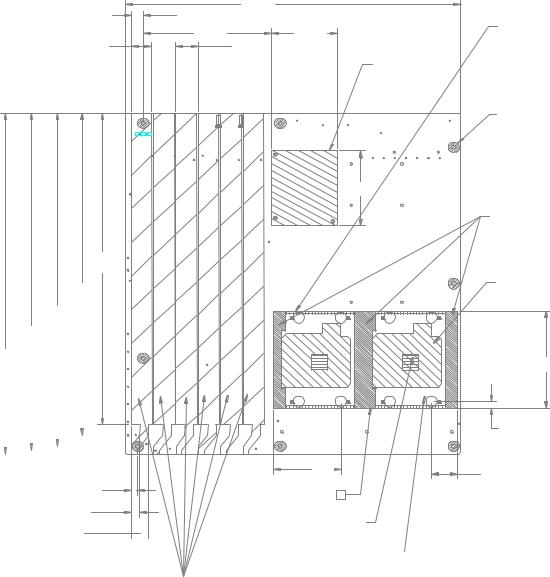
SOCKET AREA, NO COMPONENT
PLACEMENT ALLOWED, 2 PLACES
93.98 [ 3.700 ]
6.35 [ 0.250 ]
60.96 |
|
22.86 |
|
[ 2.400 |
] |
||
|
|||
|
|
3 |
.118" [3.81mm] MAX COMPONENT HEIGHT RESTRICTION, 2 PLACES
HEATSINK AREA. .325" [8.26mm] MAX
COMPONENT HEIGHT RESTRICTIO, 2 PLACES
MAX HEIGHT OF COMPONENTS AND MATING COMPONENTS
SHALL NOT EXCEED 15.24mm [.600"]
Figure 5. Restricted Areas on Side 1
Revision 1.7 |
9 |
|
|
|
Intel order number: D41763-008 |
||
Server Board Overview |
Intel® Server Boards S5000PSL and S5000XSL TPS |
|
|
|
|
|
|
|
LIMITED COMPONENT HEIGHT |
|
|
|
2X |
3.120 |
|
|
|
|||
|
|
|
|
|
|
|
.058" MAXIMUM 13 PLACES |
|
|
|
|
[ 0.1228 |
] |
|
|
|||
|
|
|
|
|
|
|
|
|
|
|
|
|
78.74 |
|
|
|
|
|
|
|
|
|
|
|
|
|
|
|
|
|
|
[ 3.100 |
] |
|
|
|
|
|
7.620 |
|
TYP |
|
|
|
|
|
20.320 |
|
|
|
|
|
|
|
||
|
[ |
0.3000 |
] |
|
|
|
|
|
|
[ 0.8000 |
] |
|
|
|
|
|
|
|
|
|
|
|
|
|
|
|
|
|
|
|
|
|
|
|
|
|
SEE DETAIL B |
20.320 |
|
|
|
|
|
|
|
|
|
|
|
|
|
|
|
|
||
[ 0.8000 |
] |
|
|
3 |
|
R 25.40 |
|
2X |
8.000 |
|
|
|
|
|
|
|
||
|
11 PLCS |
|
|
|
|
|
|
|
2X |
0.350 |
|
|
|
|||||
|
|
|
|
|
|
|
|
[ 1.000 |
] |
|
[ 0.3150 |
] |
|
[ |
0.0138 |
] |
|
|
|
|
|
|
|
|
|
|
TYP |
|
|
|
|
|
|
|
|
|
|
|
|
|
|
|
|
|
|
|
|
NO COMPONENTS ALLOWED |
|
|
|
66.554 |
|
|
||
5.08 |
|
|
|
|
|
|
|
|
|
TRACES OKAY IN THIS REGION |
|
|
|
|
|
|||
|
|
|
|
|
|
|
|
|
|
|
|
[ 2.6202 |
] |
|
||||
[ 0.200 |
] |
|
|
|
|
|
|
|
|
|
|
|
|
|
|
|||
|
|
|
|
|
|
|
|
|
|
|
|
|
|
|
|
|||
|
TYP |
|
|
|
|
|
|
|
|
|
|
|
|
|
|
|
|
|
R 14.730 |
|
TYP |
|
|
|
|
|
|
|
|
|
|
|
|
|
|
||
|
[ 0.5799 |
|
] |
|
|
|
|
|
|
|
|
|
|
|
|
|
|
|
|
|
|
|
|
|
|
|
|
|
|
|
|
|
|
|
|
177.80 |
|
|
|
|
|
|
|
|
|
|
|
|
|
|
|
|
|
|
[ 7.000 |
] |
|
|
|
|
|
|
|
|
|
|
|
|
|
Ø10.160 |
|
GROUND PAD |
|
|
|
|
|
|
|
|
|
|
|
|
|
|
|
|
[ 0.4000 |
] |
|
|
|
|
|
|
|
|
|
|
|
|
|
|
|
|
|
NO COMPONENT |
|
|
|
||
|
|
|
|
|
|
|
|
|
|
|
|
|
1 PLACE |
|
|
|
|
|
.100 [2.54<<] MAX COMPONENT |
|
|
|
|
|
|
|
|
|
|
|
|
|
|
|
|
||
HEIGHT IN THESE ZONES |
|
|
|
|
|
|
|
|
|
|
|
|
|
|
|
|
|
|
|
|
|
|
|
|
|
|
|
|
|
|
|
|
2 |
|
|
|
|
96.52 |
|
|
|
|
|
|
|
|
|
|
|
|
|
|
|
|
|
|
[ 3.800 |
] |
|
|
|
|
|
|
|
|
|
|
|
|
|
|
|
|
|
|
|
|
|
57.15 |
|
|
|
|
|
|
|
|
|
|
|
|
|
|
|
|
|
|
[ 2.250 |
] |
|
|
|
|
|
|
|
|
|
|
|
|
|
12.07 |
|
|
|
|
|
|
|
|
|
|
|
|
|
|
|
|
|
|
[ |
0.475 |
] |
|
|
|
|
|
|
|
|
|
|
|
|
|
|
|
|
|
|
|
7.62 |
|
|
|
|
|
|
|
|
|
|
|
|
|
|
|
|
|
|
[ |
0.300 |
] |
|
|
|
|
|
|
|
|
|
|
|
|
|
|
|
|
|
|
|
5.08 |
|
|
|
12.70 |
|
|
|
|
|
|
||
|
|
|
|
|
|
|
|
|
[ |
0.500 |
] |
|
|
|
|
|
||
|
|
|
|
|
|
[ |
0.200 |
] |
|
|
|
|
|
|
|
|||
|
|
|
|
|
|
|
|
|
|
|
|
|
|
|
|
|||
17.78 |
|
|
|
|
|
|
|
|
5.08 |
|
|
|
|
|
|
NO COMPONENTS |
||
[ 0.700 |
] |
|
|
|
|
|
|
|
[ 0.200 |
] |
|
|
|
|
||||
|
|
|
|
|
|
|
|
|
|
|
|
|
|
|
|
|
|
THIS ZONE 16 PLCS |
CEK HEATSINK SPRING PLATE ZONE
NO COMPONENT PLACEMENT OR
THROUGH HOLE LEADS ALLOWED
Figure 6. Restricted Areas on Side 2
10 |
Revision 1.7 |
|
Intel order number: D41763-008

Intel® Server Boards S5000PSL and S5000XSL TPS |
Server Board Overview |
|
|
|
|
5.00 |
|
5.00 |
|
|
|
|
|
|
|
|
[ |
0.197 |
] |
[ 0.197 |
] |
|
|
|
|
3X |
4.00 |
|
|
|
|
|
|
|
|
|
|
[ |
0.157 |
] |
|
|
|
|
|
|
|
|
|
|
|
|
|
3X |
3.00 |
|
|
|
|
|
|
|
|
|
|
[ 0.118 |
] |
3X |
10.13 |
|
|
|
|
|
|
|
|
|
|
[ |
0.399 |
] |
|
|
|
|
|
|
|
|
|
|
|
|
|
|
|
CHASSIS ID PADS |
|
|
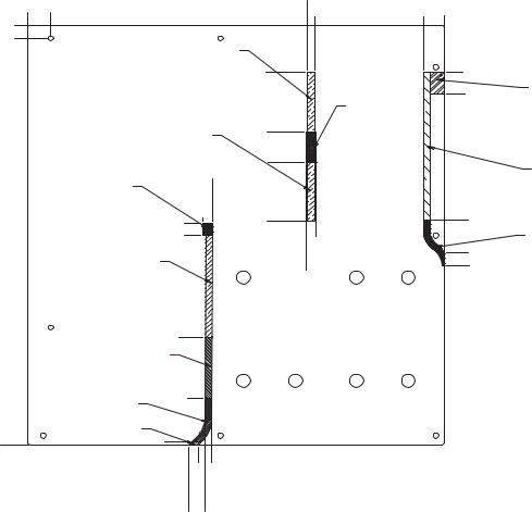
Figure 7. Restricted Areas on Side 2, “Detail B”
Revision 1.7 |
11 |
|
Intel order number: D41763-008
Server Board Overview |
Intel® Server Boards S5000PSL and S5000XSL TPS |
16.510 [0.6500] |
0.000 [0.0000] |
10.160 [0.4000]
0.000 [0.0000]
|
14.0mm COMPONENT HEIGHT |
|
||
|
LIMIT DEFINED BY DUCT DETAIL |
|||
|
|
|
|
26.635 |
|
|
|
|
[1.0486] |
|
14.0mm COMPONENT HEIGHT |
73.482 |
||
|
[2.8930] |
|||
|
LIMIT DEFINED BY DUCT DETAIL |
|||
|
|
|||
|
|
[4.3839] |
118.351 [4.6595] |
97.846 |
|
|
|
|
[3.8522] |
SUPPORT AREA, |
|
|
|
|
NO COMPONENT |
111.351 |
|
|
|
ALLOWED |
|
|
|
|
|
|
|
|
|
|
145.600 [5.7323] |
|
|
143.732 |
|
|
|
[5.6588] |
|
|
154.685 [6.0900] |
|
|
|
15.0mm COMPONENT HEIGHT |
|
|
|
|
LIMIT DEFINED BY DUCT DETAIL |
|
|
|
|
|
235.085 [9.2553] |
|
|
|
|
9.0 mm COMPONENT HEIGHT |
|
|
|
|
LIMIT DEFINED BY DUCT DETAIL |
|
|
|
|
27.0 mm COMPONENT HEIGHT |
282.585 |
|
|
|
[11.1254] |
|
|
|
|
LIMIT DEFINED BY DUCT DETAIL |
|
|
|
|
13.0 mm COMPONENT HEIGHT |
|
|
|
|
LIMIT DEFINED BY DUCT DETAIL |
|
|
|
320.040 |
317.580 [12.5032] |
|
|
|
[12.6000] |
|
|
|
|
|
|
|
107.920 [4.2488] |
117.851 [4.6398] |
|
|
101.402 [3.9922] |
112.851 [4.4430] |
|
188.152 [7.4076] |
193.152 [7.6044] |
273.091 [10.7516] |
288.290 [11.3500] |
|
|
26.578 [1.0464] |
|
|
|
43.302 [1.7048] |
16.5mm COMPONENT HEIGHT |
|
SUPPORT AREA, |
LIMIT DEFINE BY DUCT DETAIL |
|
|
NO COMPONENT |
|
|
|
ALLOWED |
|
|
|
|
|
1.25mm COMPONENT HEIGHT |
|
|
|
LIMIT DEFINE BY DUCT DETAIL |
|
|
143.136 [5.6353] |
|
194.152 [7.6438] |
|
|
NO COMPONENT ALLOWED |
|
168.123 [6.6190] |
|
|
|
|
|
|
187.152 [7.3682] |
|
178.578 [7.0306] |
|
|
|
|
Figure 8. CPU and Memory Duct Keepout
12 |
Revision 1.7 |
|
|
|
Intel order number: D41763-008 |