


INSTRUCTION SET REFERENCE
3.1.2.Operation
The “Operation” section contains an algorithmic description (written in pseudo-code) of the instruction. The pseudo-code uses a notation similar to the Algol or Pascal language. The algorithms are composed of the following elements:
•Comments are enclosed within the symbol pairs “(*” and “*)”.
•Compound statements are enclosed in keywords, such as IF, THEN, ELSE, and FI for an if statement, DO and OD for a do statement, or CASE ... OF and ESAC for a case statement.
•A register name implies the contents of the register. A register name enclosed in brackets implies the contents of the location whose address is contained in that register. For example, ES:[DI] indicates the contents of the location whose ES segment relative address is in register DI. [SI] indicates the contents of the address contained in register SI relative to SI’s default segment (DS) or overridden segment.
•Parentheses around the “E” in a general-purpose register name, such as (E)SI, indicates that an offset is read from the SI register if the current address-size attribute is 16 or is read from the ESI register if the address-size attribute is 32.
•Brackets are also used for memory operands, where they mean that the contents of the memory location is a segment-relative offset. For example, [SRC] indicates that the contents of the source operand is a segment-relative offset.
•A ¬ B; indicates that the value of B is assigned to A.
•The symbols =, ¹, ³, and £ are relational operators used to compare two values, meaning equal, not equal, greater or equal, less or equal, respectively. A relational expression such as A = B is TRUE if the value of A is equal to B; otherwise it is FALSE.
•The expression “<< COUNT” and “>> COUNT” indicates that the destination operand should be shifted left or right, respectively, by the number of bits indicated by the count operand.
The following identifiers are used in the algorithmic descriptions:
•OperandSize and AddressSize—The OperandSize identifier represents the operand-size attribute of the instruction, which is either 16 or 32 bits. The AddressSize identifier represents the address-size attribute, which is either 16 or 32 bits. For example, the following pseudo-code indicates that the operand-size attribute depends on the form of the CMPS instruction used.
IF instruction = CMPSW
THEN OperandSize ← 16;
ELSE
IF instruction = CMPSD
THEN OperandSize ← 32;
FI;
FI;
3-5

INSTRUCTION SET REFERENCE
See “Operand-Size and Address-Size Attributes” in Chapter 3 of the Intel Architecture Software Developer’s Manual, Volume 1, for general guidelines on how these attributes are determined.
•StackAddrSize—Represents the stack address-size attribute associated with the instruction, which has a value of 16 or 32 bits (see “Address-Size Attribute for Stack” in Chapter 4 of the Intel Architecture Software Developer’s Manual, Volume 1 ).
•SRC—Represents the source operand.
•DEST—Represents the destination operand.
The following functions are used in the algorithmic descriptions:
•ZeroExtend(value)—Returns a value zero-extended to the operand-size attribute of the instruction. For example, if the operand-size attribute is 32, zero extending a byte value of –10 converts the byte from F6H to a doubleword value of 000000F6H. If the value passed to the ZeroExtend function and the operand-size attribute are the same size, ZeroExtend returns the value unaltered.
•SignExtend(value)—Returns a value sign-extended to the operand-size attribute of the instruction. For example, if the operand-size attribute is 32, sign extending a byte containing the value –10 converts the byte from F6H to a doubleword value of FFFFFFF6H. If the value passed to the SignExtend function and the operand-size attribute are the same size, SignExtend returns the value unaltered.
•SaturateSignedWordToSignedByte—Converts a signed 16-bit value to a signed 8-bit value. If the signed 16-bit value is less than –128, it is represented by the saturated value – 128 (80H); if it is greater than 127, it is represented by the saturated value 127 (7FH).
•SaturateSignedDwordToSignedWord—Converts a signed 32-bit value to a signed 16-bit value. If the signed 32-bit value is less than –32768, it is represented by the saturated value –32768 (8000H); if it is greater than 32767, it is represented by the saturated value 32767 (7FFFH).
•SaturateSignedWordToUnsignedByte—Converts a signed 16-bit value to an unsigned 8-bit value. If the signed 16-bit value is less than zero, it is represented by the saturated value zero (00H); if it is greater than 255, it is represented by the saturated value 255 (FFH).
•SaturateToSignedByte—Represents the result of an operation as a signed 8-bit value. If the result is less than –128, it is represented by the saturated value –128 (80H); if it is greater than 127, it is represented by the saturated value 127 (7FH).
•SaturateToSignedWord—Represents the result of an operation as a signed 16-bit value. If the result is less than –32768, it is represented by the saturated value –32768 (8000H); if it is greater than 32767, it is represented by the saturated value 32767 (7FFFH).
•SaturateToUnsignedByte—Represents the result of an operation as a signed 8-bit value. If the result is less than zero it is represented by the saturated value zero (00H); if it is greater than 255, it is represented by the saturated value 255 (FFH).
3-6
INSTRUCTION SET REFERENCE
•SaturateToUnsignedWord—Represents the result of an operation as a signed 16-bit value. If the result is less than zero it is represented by the saturated value zero (00H); if it is greater than 65535, it is represented by the saturated value 65535 (FFFFH).
•LowOrderWord(DEST * SRC)—Multiplies a word operand by a word operand and stores the least significant word of the doubleword result in the destination operand.
•HighOrderWord(DEST * SRC)—Multiplies a word operand by a word operand and stores the most significant word of the doubleword result in the destination operand.
•Push(value)—Pushes a value onto the stack. The number of bytes pushed is determined by the operand-size attribute of the instruction. See the “Operation” section in “PUSH—Push Word or Doubleword Onto the Stack” in this chapter for more information on the push operation.
•Pop() removes the value from the top of the stack and returns it. The statement EAX ← Pop(); assigns to EAX the 32-bit value from the top of the stack. Pop will return either a word or a doubleword depending on the operand-size attribute. See the “Operation” section in Chapter 3, “POP—Pop a Value from the Stack” for more information on the pop operation.
•PopRegisterStack—Marks the FPU ST(0) register as empty and increments the FPU register stack pointer (TOP) by 1.
•Switch-Tasks—Performs a standard task switch.
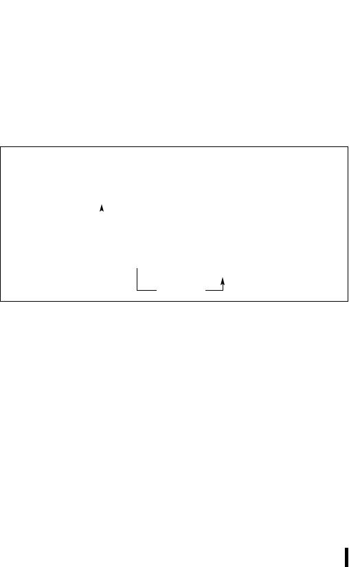
•Bit(BitBase, BitOffset)—Returns the value of a bit within a bit string, which is a sequence of bits in memory or a register. Bits are numbered from low-order to high-order within registers and within memory bytes. If the base operand is a register, the offset can be in the range 0..31. This offset addresses a bit within the indicated register. An example, the function Bit[EAX, 21] is illustrated in Figure 3-1.
31 |
21 |
0 |
|
|
|
 BitOffset = 21
Figure 3-1. Bit Offset for BIT[EAX,21]
If BitBase is a memory address, BitOffset can range from –2 GBits to 2 GBits. The addressed bit is numbered (Offset MOD 8) within the byte at address (BitBase + (BitOffset DIV 8)), where DIV is signed division with rounding towards negative infinity, and MOD returns a positive number. This operation is illustrated in Figure 3-2.
3-7
INSTRUCTION SET REFERENCE
3.1.3.Flags Affected
The “Flags Affected” section lists the flags in the EFLAGS register that are affected by the instruction. When a flag is cleared, it is equal to 0; when it is set, it is equal to 1. The arithmetic and logical instructions usually assign values to the status flags in a uniform manner (see Appendix A, EFLAGS Cross-Reference, in the Intel Architecture Software Developer’s Manual, Volume 1). Non-conventional assignments are described in the “Operation” section. The values of flags listed as undefined may be changed by the instruction in an indeterminate manner. Flags that are not listed are unchanged by the instruction.
7 5 0 7 0 7 0
|
|
|
|
|
|
|
|
|
|
|
|
|
|
|
BitBase + 1 |
|
BitBase |
|
|
|
BitBase − 1 |
|
|||||||
|
|
|
|
|
||||||||||
|
|
|
|
|
|
|
|
|
|
|
|
|
|
|
|
|
|
|
|
|
|
|
|
|
|
|
|
|
|
|
|
|
|
BitOffset = +13 |
|
|
|
|
|
|
|
|
||
|
|
|
|
|
|
|
|
|
|
|
|
|||
7 |
|
|
|
|
0 |
7 |
|
0 |
7 |
5 |
|
0 |
||
|
|
|
|
|
|
|
|
|
|
|
||||
|
|
|
|
|
|
|
|
|
|
|
|
|
|
|
|
BitBase |
|
BitBase − 1 |
|
|
|
BitBase − 2 |
|
||||||
BitOffset = −
Figure 3-2. Memory Bit Indexing
3.1.4.FPU Flags Affected
The floating-point instructions have an “FPU Flags Affected” section that describes how each instruction can affect the four condition code flags of the FPU status word.
3.1.5.Protected Mode Exceptions
The “Protected Mode Exceptions” section lists the exceptions that can occur when the instruction is executed in protected mode and the reasons for the exceptions. Each exception is given a mnemonic that consists of a pound sign (#) followed by two letters and an optional error code in parentheses. For example, #GP(0) denotes a general protection exception with an error code of 0. Table 3-2 associates each two-letter mnemonic with the corresponding interrupt vector number and exception name. See Chapter 5, Interrupt and Exception Handling, in the Intel Architecture Software Developer’s Manual, Volume 3 , for a detailed description of the exceptions.
Application programmers should consult the documentation provided with their operating systems to determine the actions taken when exceptions occur.
3-8

INSTRUCTION SET REFERENCE
3.1.6.Real-Address Mode Exceptions
The “Real-Address Mode Exceptions” section lists the exceptions that can occur when the instruction is executed in real-address mode.
Table 3-2. Exception Mnemonics, Names, and Vector Numbers
Vector |
|
|
|
No. |
Mnemonic |
Name |
Source |
|
|
|
|
0 |
#DE |
Divide Error |
DIV and IDIV instructions. |
1 |
#DB |
Debug |
Any code or data reference. |
3 |
#BP |
Breakpoint |
INT 3 instruction. |
4 |
#OF |
Overflow |
INTO instruction. |
5 |
#BR |
BOUND Range Exceeded |
BOUND instruction. |
6 |
#UD |
Invalid Opcode (Undefined |
UD2 instruction or reserved opcode.1 |
|
|
Opcode) |
|
7 |
#NM |
Device Not Available (No Math |
Floating-point or WAIT/FWAIT |
|
|
Coprocessor) |
instruction. |
8 |
#DF |
Double Fault |
Any instruction that can generate an |
|
|
|
exception, an NMI, or an INTR. |
10 |
#TS |
Invalid TSS |
Task switch or TSS access. |
11 |
#NP |
Segment Not Present |
Loading segment registers or accessing |
|
|
|
system segments. |
12 |
#SS |
Stack Segment Fault |
Stack operations and SS register loads. |
13 |
#GP |
General Protection |
Any memory reference and other |
|
|
|
protection checks. |
14 |
#PF |
Page Fault |
Any memory reference. |
16 |
#MF |
Floating-Point Error (Math Fault) |
Floating-point or WAIT/FWAIT |
|
|
|
instruction. |
17 |
#AC |
Alignment Check |
Any data reference in memory.2 |
18 |
#MC |
Machine Check |
Model dependent.3 |
NOTES:
1.The UD2 instruction was introduced in the Pentium® Pro processor.
2.This exception was introduced in the Intel486™ processor.
3.This exception was introduced in the Pentium processor and enhanced in the Pentium Pro processor.
3.1.7.Virtual-8086 Mode Exceptions
The “Virtual-8086 Mode Exceptions” section lists the exceptions that can occur when the instruction is executed in virtual-8086 mode.
3-9