

Английский для Тх / adsorptive Bubble Separation and Dispersed Air Flotation
.pdfAdsorptive Bubble Separation and Dispersed Air Flotation |
101 |
Fig. 5. Cross section of plateau border and films in foam.
The bubbles in the froth flow (i.e., foam) press against each other, more or less flattening the faces or films in between, particularly for dryer foams. These films intersect three at a time to form capillaries or channels, which are often called plateau borders (Fig. 5 ). The uniform foam bubbles are nearly regular dodecahedra, which implies that there is a dihedral angle of 120° between intersecting films. Foam drainage occurs primarily through the interconnecting network of capillaries rather that from film to film. The flow through the capillaries is incompressible and laminar.
In froth flow of foam separation column, bubble coalescence within the rising foam is important. Coalescence in foam is of two types. The first is gas diffusion or bubble growth, which arises from the difference in pressure between adjacent air bubbles of differing size. As a result of the surface tension, the smaller air bubble has a higher pressure than the larger. This causes air to diffuse from the smaller bubble, across the film, to the larger bubble. Accordingly, the larger bubble grows larger while the smaller continues to shrink. The smaller bubble will completely disappear if sufficient time is given. The overall affect is a decrease in film surface area.
The second cause of coalescence is the film rupture between bubbles. This can easily be very significant. Physically, the film rupture stems from a depletion of surfactant at the film surface when the surface is stretched. The film stability is commonly ascribed in large measure to the so-called Marangoni effect and Gibbs effect. The Marangoni effect involves the inability of surfactant molecules to diffuse instantaneously to any locally stretched area in the film surface. The resulting lag permits the stretched surface to be momentarily depleted of surfactant. The Gibbs effect involves
102 |
Lawrence K. Wang |
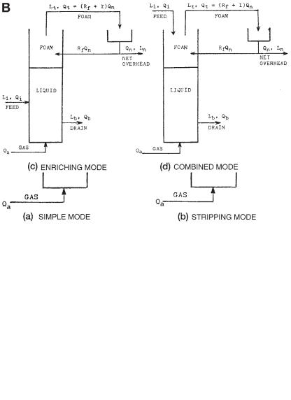
Fig. 6. (A) Foam separation modes (without external reflux). (B) Foam separation modes (with external reflux) (43 ).
the possible insufficiency of molecules within the film liquid to recoat the stretched surface completely regardless of diffusion rate. Another mechanism is the electrostatic repulsion between the charged surfaces that opposes film thinning and foam rupture. This can be important with some ionic surfactants in thin films.
Whatever the cause, coalescence within the rising foam furnishes internal reflux that enriches the foam and, therefore, increases the solute concentration in the overflow foam stream. Foam coalescence due to external reflux will be discussed later.
There are four modes for the continuous foam separation process: the simple mode, the stripping mode, the enriching mode, and the combined mode. Only the first two

Adsorptive Bubble Separation and Dispersed Air Flotation |
103 |
modes (simple and stripping), which involve no external reflux, are of interest to the feasibility studies. This is because the simple and the stripping modes (Fig. 6A) are easy to operate in a small laboratory. Besides, once a particular type of foam separation process has been proved to be feasible by its simple mode or stripping mode operations, the enriching mode or the combined mode (Fig. 6B), which both involve external reflux, can readily be operated in a larger pilot-plant scale or full scale successfully.
External reflux can be accomplished simply by a mechanical or any other suitable means, and then returning a portion of the collapsed foam to the top of the cell, as shown in Fig. 6B (enriching mode and combined mode). In the external reflux operation, some collapsed foam serves as reflux and drains back down through the rising foam. The resulting countercurrent contact enriches the rising interstitial liquid and thus enriches the overflow. For external reflux, either “dephlegmation” or total external coalescence is required. Dephlegmation is the deliberate partial collapse of the foam at the top of the foam cell. By whatever means accomplished, the partial reflux so created drains back down through the rising foam thus enriching it. The uncollapsed portion of the foam simply flows off overhead, and can be broken separately. Total external coalescence is accomplished simply by breaking (collapsing) all the overhead foam in some suitable manner, and then returning a portion of the collapsed foam to the top of the cell, as shown in Fig. 6B. Enriching the foam is also expected.
For the cells of simple mode (Fig. 6A), feed is introduced into the liquid pool under the following three assumptions: there is no appreciable bubble coalescence in the rising foam with the column; foam leaving the liquid surface is in equilibrium with the completely mixed bulk solution; and the bulk solute concentration is equal to the drain solute concentration. For a sufficiently long column, the separation ratio Lt/Lb and the stripping ratio Lb/Li are given by Eqs. (15) and (16):
Lt /Lb |
1 + f Qa Eb/Lb Qt |
(15) |
Lb /Li |
1 f Qa Eb/Li Qi |
(16) |
Equation ( 15) is derived from Eq. (14) by replacing L with Lb while Eq. (16) is derived from Eqs. (8), (9), and (15). The surface to volume ratio of bubble f ) for the simple mode (Fig. 6A) is equal to 6/d The surface excess value (Eb) is in equilibrium with drain concentration Lb. d is the effective average bubble diameter.
For the cells of stripping mode (Fig. 6A), feed is introduced into the system some distance above the liquid pool. It tends to replace the rising interstitial liquid of pool concentration with downcoming liquid of feed concentration. Therefore, the foam leaving the liquid surface is in equilibrium with the feed solution. L in Eq. ( 14) , should be replaced with Li The results of the countercurrent stripping action are
Lt |
Li |
+ f |
Qa Ei /Qt |
( 17) |
Lb |
Li |
– f |
Qa Ei /Qb |
(18) |
f |
6.59/d |
(19) |
||
|
|
|
|
|
in which the surface to volume ratio of air bubble ( f ) for stripping mode has been changed to 6.59/d The surface excess value is in equilibrium with the feed concentration Li. d is the effective average bubble diameter.

104 |
|
|
|
|
|
|
Lawrence K. Wang |
|
|
T |
|
able 4 |
|
|
|
|
|
|
|
|
|
|
|
|||
|
Foam Separation Modes |
|
|
|||||
|
|
|
|
|
||||
|
1. Simple mode |
|
|
|
||||
|
|
|
Lt |
Lb + f QaEb /Qt |
(15) |
|
||
|
|
|
Lb |
Li – f QaEb /Qi |
(16) |
|
||
|
|
|
f |
6/d |
|
(13) |
|
|
|
2. Stripping mode |
|
|
|
||||
|
|
|
Lt |
Li |
+ f |
QaEi /Qt |
(17) |
|
|
|
|
Lb |
Li |
– f |
QaEi /Qb |
(18) |
|
|
|
|
f |
6.59/d |
|
(19) |
|
|
|
3. Enriching mode |
|
|
|||||
|
|
|
Ln |
Lb + f |
QaEb/Qn |
(20) |
|
|
|
|
|
Lb |
Li |
– f |
QaEb /Qt |
(21) |
|
|
|
|
f |
6.59 – 0.59/(Rf + 1) |
(22) |
|
||
|
4. Combined mode |
|
|
|||||
|
|
|
Ln = Li + f QaEi /Qn |
(23) |
|
|||
|
|
|
Lb |
Li |
– f |
QaEi /Qb |
(24) |
|
|
|
|
f |
6.59/d |
|
(19) |
|
|
Similarly the cell performance equations for the enriching mode and combined mode can be derived. Table 4 summarizes the cell performance Eqs. ( 13)–(24) of foam separation.
It should be noted that the assumption of no appreciable bubble coalescence in the rising foam is difficult to be measured to any extent and magnitude because the rising foam is not sufficiently stable. Although bubble coalescence within the foam is quite often the case, it frequently goes unrecognized because of nonuniformity in bubble size, which makes changes difficult to detect by eyes, the effect of such internal coalescence is to destroy some bubble surface, thus releasing adsorbed material that trickles back down through the rising foam, enriching the foam, and, therefore, increasing the solute concentration in the overflow foam stream. Using a different surface to volume ratio ( f ) for a different mode of operation resulted from the consideration of bubble coalescence in the rising foam.
An empirical model can be developed, relating some operational variables of continuous foam separation (simple mode and stripping mode)
Qb |
a1 a2Li + a3 Tc |
a4 Qa |
(25) |
and |
|
|
|
Lb |
b 1 + b2 Li + b3 Tc |
b4 Qa |
(26) |
in which a1 a2 a3 a4 b 1 b2 |
b3, and b4 are constants, and Tc |
is temperature in °C. |
|
In general, surface excess E varies with its equilibrium concentration L in a foam separation reactor. For trace concentration of surfactants, this variation can often be repre-
sented by a linear isotherm (77,78) |
|
E KL |
(27) |
where K is an equilibrium constant for surface adsorption, cm; L is the concentration of surface active solute, g-mole/cm3; and E is the solute surface excess in equilibrium with L g-mole/cm2

Adsorptive Bubble Separation and Dispersed Air Flotation |
105 |
For a surfactant that is present in a foam separation reactor at a concentration near or above its critical micelle concentration, the surface excess may be approximately a constant representing a completely saturated air–water interface:
E K |
(28) |
where K is another equilibrium constant for surface adsorption, g-mole/cm2
For a better foam separation than that obtainable with the simple mode, the process operation can be cascaded by employing one of the countercurrent modes as shown in Figs. 6A and 6B. For the countercurrent modes of process operation, the number of transfer units (NTU) can be calculated in terms of an upflowing stream of interstitial liquid plus bubble surface, and a downflowing stream of just interstitial liquid. If the surfactant concentration in the upflowing interstitial liquid is L and the solute surface excess at the bubble surface is E (which is taken to be equilibrium with L), then the effective concentration in the upflowing stream on a gas-free basis is generalized as
y L + f ′ Q E/Q (29)
a
where y effective concentration of solute in the upflow within a foam separation reactor on a gas-free basis, g-mole/cm3 of liquid; L concentration of surface active solute, g-mole/cm3 Q volumetric rate of liquid upflow in a foam separation reactor, cm3/s; and f ratio of bubble surface area to bubble volume, cm –1 . The number of transfer units (NTU) in the foam based on the upflow stream can be calculated by Eq. (30).
|
|
Lt |
|
||
|
|
NTU ³ |
dy |
|
(30) |
|
|
y * y |
|||
|
|
y* |
|
||
where y* is the ef |
|
fective concentration of solute, in equilibrium with Lt |
in the upflow |
||
|
|||||
|
|||||
within a foam separation reactor on a gas-free basis, g-mole/cm3 |
|
||||
10. CHEMICAL REAGENTS FOR ADSORPTIVE BUBBLE SEPARATION
Promoters or collectors provide the substances to be separated with a water-repellent air-avid coating that will adhere to air bubbles. Typical collectors for flotation of metallic sulfides and native metals are dithiophosphates and xanthates. Fatty acids and their soaps, petroleum sulfonates, and sulfonated fatty acids are widely used as collectors in flotation of fluorspar, iron ore, phosphate rock, and others. Fuel oil and kerosene are used as collectors for coal, graphite, sulfur, and molybdenite. Cationic collectors such as fatty amines and amine salts are widely used for separation of quartz, potash, and silicate minerals.
Pine oil, cresylic acid, aliphatic alcohols, and polypropylene glycol ether are commonly used as the “frothers.”
Bubble separation “modifiers” include several classes of chemicals described below: activators, alkalinity regulators, depressants, deflocculants, and defoaming agents.
“Activators” are used to make a mineral surface amenable to collector coating. Sodium sulfide is used to coat oxidized copper and lead minerals so that they can be floated by a sulfide mineral collector. Copper ion is used to activate sphalerite (ZnS), rendering the sphalerite surface capable of adsorbing a xanthate or dithiophosphate collector.

106 |
Lawrence K. Wang |
Alkalinity regulators” such as caustic soda, lime, soda ash, and sulfuric acid are used to control or adjust pH, a very critical factor in many adsorptive bubble separations.
“Depressants” assist in selectivity (sharpness of separation) or stop unwanted minerals from floating. Typical depressants are sodium or calcium cyanide to depress pyrite (FeS 2), while floating galena (PbS), sphalerite (ZnS), or copper sulfides; zinc sulfate to depress ZnS while floating Pbs; sodium ferrocyanide to depress copper sulfides while floating molybdenite (MoS 2); lime to depress pyrite; sodium silicate to depress quartz; quebracho to depress calcite (CaCO3) during fluorite (CaF2) separation; lignin sulfonates and dextrins to depress graphite and talc during sulfide separation.
“Dispersants or deflocculants” are important for control of slimes, which sometimes interfere with selectivity and increase reagent consumption. Soda ash, sodium silicate, lime, and lignin sulfonates are used for this purpose.
A “defoaming agent” is a formulation of surface-active materials used at low concentrations to prevent the formation of unwanted foam or to destroy foam which has formed.
Any chemicals or substances which can be dosed to increase the efficiency of a flotation cell is termed the “flotation aid.”
11. LABORATORY FOAM SEPARATION TESTS
11.1. Sequencing Batch Reactor Foam Separation
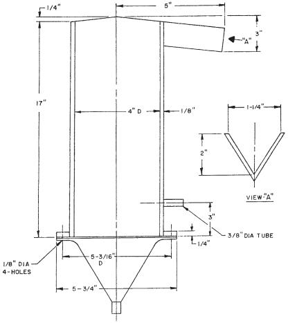
A bench-scale foam separation unit, Foamer Tester, has been developed by Krofta Engineering Corporation and Lenox Institute of Water Technology, both in Lenox, MA, USA. It is for use in these types of SBR-foam separation experiments. Figures 7 and 8 show the tester dimensions and piping arrangements, respectively.
To start the SBR foam separation (or dispersed air flotation, or induced air flotation) experiments, sufficient volume of raw water is adjusted to the desired pH with 1.0 N sodium hydroxide or 1.0 N sulfuric acid, an appropriate amount of surfactant is added to the raw water, and the mixture is poured into the Foamer Tester (Fig. 7). Compressed air is then diffused through the liquid mixture by means of a plastic cloth grid (Fig. 8). Foam is withdrawn from the top and collected in a container. The run is allowed to proceed until no additional foam is formed. A sample of the bulk liquid near the reactor bottom is analyzed for pH, color, turbidity, and other water quality parameters. The foam is collapsed in a beaker and its volume is measured.
From batch foam separation experiments, one may be able to determine the feasibility of the process and the approximate optimum chemical dosages.
11.2. Continuous Foam Separation
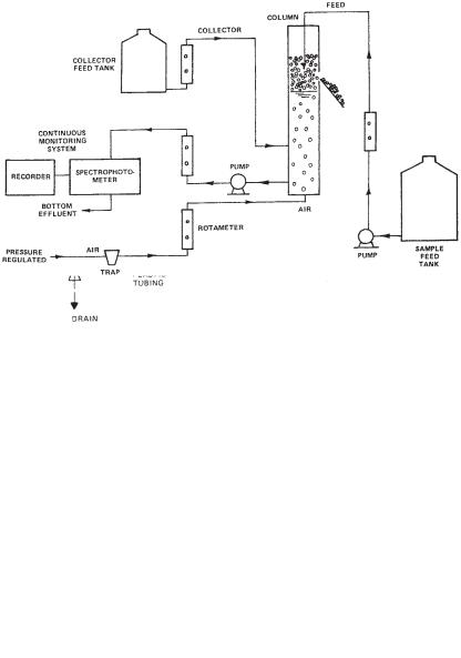
Figure 9 shows an experimental set-up for continuous foam separation experiment. Continuous pilot plant operations allow the engineers to determine not only the optimum chemical dosages but also the optimum operational conditions in terms of flows, feed locations, chemical dosages, and so on.
For the continuous foam separation study, sample solution is prepared, mixed well, and placed in the large feed tank. Four liters of initial sample are taken with the desired amount of collector added, the initial color, turbidity, optical density, surfactant concentration, streaming current reading, conductivity, and pH are determined. The collector is also uniformly prepared and placed in a smaller feed tank. The solutions of influent feed
Adsorptive Bubble Separation and Dispersed Air Flotation |
107 |
Fig. 7. Dimensions of a bench-scale batch dispersed air flotation unit.
and collector are pumped into the foam separation cell at specified rates for each run. The concentrations in the feed tanks are adjusted to provide the desired concentrations of target solute and of collector. Compressed air is diffused through the solution by means of the coarse gas diffuser. After start-up, the bulk liquid is pumped through the system, and the optical density is continuously recorded. The run is continued until a steady state is reached (i.e., there is no change in the optical density). During the steady state, the bubble velocity and bubble size are measured, Samples of bottom effluent and collapsed foam are taken throughout the entire experiment. Samples are analyzed for color, optical density, residual solute concentration, residual surfactant concentration, turbidity, streaming current reading, conductivity, and pH.
12. ENGINEERING APPLICATIONS
12.1. De-inking Process for Waste Paper Purification and Recycle
Many books on the market are now printed on recycled paper containing almost 80% recycled fibers produced in a de-inking plant equipped with a dispersed flotation clarifier.
108 |
Lawrence K. Wang |
Fig. 8. Piping arrangement of a bench-scale batch dispersed air flotation system.
Fig. 9. Apparatus for continuous foam separation experiments.
This section introduces a real case history in the United Kingdom. St Regis Paper Co. Ltd. is owned by David S. Smith (Holdings). In addition to eight paper mills, the holdings company includes Severnside Waste Ltd., which supplies large quantities of waste paper for recycling. The recycling plant’s process includes a two-stage de-inking treatment, shown in Fig. 10, that allows a wider range of available waste papers to be converted to high quality printing paper (123).
Water is drawn from a stream passing through the plant. During the production process, the water is recycled and reused, and eventually passes to the effluent control
Adsorptive Bubble Separation and Dispersed Air Flotation |
109 |
plant. This plant treats the water by screening, settlement, and controlled microbic action. The discharges meet the strict requirements of the regulatory authority, the UK National Rivers Authority.
12.1.1. Pulping Operation
The initial pulping is intended to breakdown and detach the ink from the fibers of the base paper. This process requires the use of some chemicals but the most significant factors are temperature, consistency, and an efficient mechanical action. The conditions achieved disintegrate the waste paper and aid the detachment of the ink from the paper surface. This pulping stage is achieved at relatively low temperature with a low energy output. Considerable attention is given to the liming of the pulping cycle which contributes to the agglomeration of sticky contaminants and aids their removal at a later stage.
To ensure that the ink has been detached and dispersed, a sample sheet of paper is prepared and checked before the stock is diluted and discharged though a coarse dumping screen, to remove large foreign objects, to a holding tank at 5 % concentration. Following further stages of progressively high density screening, the stock is diluted to 1.5 % concentration prior to de-inking.
12.1.2. First-Stage Dispersed Air Flotation for Primary De-inking
De-inking is carried out using a dispersed air flotation cell (i.e., foam separation cell), which provides good de-inking efficiency and high fiber yield with minimal water and energy consumption. Flotation de-inking places a minimal load on the effluent system, with both flow rate and chemical oxygen demand being kept relatively low. The process requires the generation of a foam by the injection of air in the presence of a chemical mix containing caustic soda for pH control, a proprietary soap as a foaming agent, with sodium silicate and hydrogen peroxide to brighten and clean. Chemical usage is low and being progressively reduced as further technical developments allow. No chlorine bleaching is used ( 123 ).
Overall de-inking efficiency of the dispersed air flotation is aided by recirculating the liquids by pumping from the top of the cell to the bottom. The foam is removed at the top of the cell by suction heads and sent to a centrifuge where the ink-loaded sludge waste is concentrated to around 50% solids for landfill disposal. The landfill site is managed by the company and is subject to strict environmental control covering the emission of landfill gases and groundwater seepage. Special attention is given to any possible heavy metal contamination. Liquid waste is directed from the centrifuge to the industrial effluent treatment plant for further treatment when necessary.
On leaving the dispersed air flotation cell, the de-inked stock is further diluted before passing through another fine screening process to remove small solids. The materials are then pumped to a drum thickener prior to he dispersion stage.
12.1.3. Second-Stage Dispersed Air Flotation for Dispersion and Secondary De-inking
Dispersion is carried out at the lowest acceptable temperature to minimize energy requirements, and is designed to complement the preliminary dispersion action in the pulper. Thickened stock is progressively dewatered to around 40% concentration in preparation for the kneader disperser stage, which breaks down the ink/fiber bonding of more difficult printed materials ( 123 ).
110 |
Lawrence K. Wang |
Dewatering ahead of kneading is an essential requirement, but throughout the entire process emphasis is placed on water recovery and re-use.
The intermediate dispersion stage contributes substantially to the reduction in dirt particles in the finished paper and allows the processing of a wider range of waste papers. The kneading action grinds down contaminants and produces an unavoidable “graying” of the stock; however, the “whiteness” is more than regained through the second stage of flotation de-inking which follows.
Although operation of the second dispersed air flotation cell is similar to that of the first, no further chemicals are added, as the inevitable carry-over from the first stage is sufficient.
Following de-inking, the stock is pumped to a second drum thickener from which, at around 6% concentration, it is available to be blended with other constituents, if required, ahead of the papermaking process.
12.1.4. Advantages
The dispersed air flotation (or induced air flotation) de-inking process allows the use of a wider range of printed waste paper. The amount of dirt in the finished paper is reduced, thereby improving quality and reducing the amount of reject paper. The brightness of the finished paper is improved without the use of chlorine bleaching.
The energy requirements are low. The demands on effluent and waste disposal are minimal. The plant is safe to operate giving minimum risk to personnel and the environment.
12.2. Flotation Process for Calcium Carbonate Recovery from Water Treatment Sludges
12.2.1. Process Description
Froth flotation is an important and common process in the present mineral industry for separating various types of minerals or compounds present as discrete particles in an aqueous slurry. The process depends on being able to coat selectively the surface of the particles so as to give them an affinity for air. Then, with the addition of a frothing agent and fine air bubbles introduced into the mixed slurry, the coated particles are collected on the air bubbles and are carried off with the froth. The uncoated wetted particles remain in the slurry. In the field of environmental engineering, froth flotation can be economically and effectively used to produce a relatively high grade calcium carbonate, with a good recovery from the sludges obtained, when using magnesium carbonate with lime for flocculation in water treatment ( 124).
The calcium carbonate recovered can be calcined to give lime for recycle to the treatment process as well as by-product lime for marketing. In addition, removal of the calcium carbonate, the major ingredient in sludge from water softening treatment plants, reduces the disposal problem to a fraction of that previously required.
In order for the flotation to be effective, the sludge must be recycled to increase the particle size of the calcium carbonate. This recycle also gives heavier flow in the settling basins, which results in faster settling rates. For the flotation to be effective, the magnesium hydroxide in the sludge must also be completely dissolved by the carbon dioxide and washed out. In the froth flotation process (used to separate the calcium carbonate from the clay, silt, or other water contaminants), an aqueous slurry of the sludge is first conditioned (mixed) with soda ash and sodium silicate to disperse the clay and