

Compact Reinforced Composite
S P I R A L S T A I R C A S E , C O P E N H A G E N
Arkitema Architects
Location
The staircase is located in Tuborg 15 building which is along Tuborg Boulevard in the new urban quarter of Tuborg Havn in Hellerup. The area was a run-down industrial zone only a few years ago, since then it has changed into a vibrant new commercial district of Copenhagen.
Architectural Statement
Rolf Kjaer, Arkitema Architects
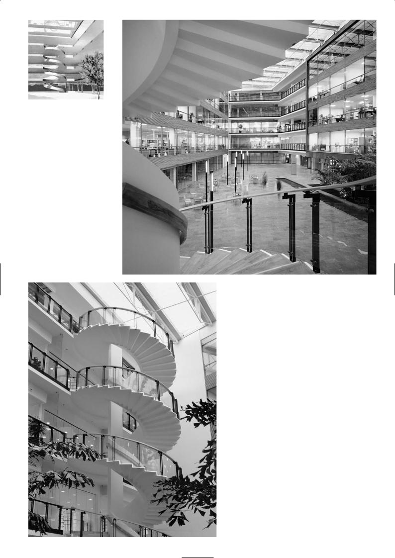
Tubor 15 is a purpose-built four-storey office building that is leased by three software companies. The staff share facilities within the building such as the foyer and the restaurant located in a bright spacious atrium where daylight floods through the glass canopied roof. Large trees and a water fountain give the atrium a touch of the great outdoors. The open staircase spiralling the east elevation of the atrium is a distinctive feature, a piece of sculptural art. Connected to the floor divisions at landing level only, it is a completely self-supporting structure.
When we first thought about the spiral staircase we had never heard of CRC, so we intended to scheme it in steel or reinforced concrete. It was only by chance that I came across CRC which is a fantastic product. We met with Bendt Aarup from CRC Technology and with our engineering colleagues at Ramboll and thus the concept of the spiral staircase evolved.
Our first idea was to design the staircase with a double balustrade and no columns and all in white concrete. Our engineers persuaded us that it was better structurally to have a column and only an interior balustrade. As we preferred not to have a detached square column, we shaped the column so it formed an integral part of the balustrade and was curved. The proportions of the spiral were then modelled on a computer using a 3D imaging programme. The leading edge was made as thin as possible as it was an important focal point. CRC is grey in colour due to the grey micro silica even though it is made with white cement. So we had it painted white using a silicate paint commonly applied to exposed concrete in Denmark.
You will see that there is a wooden plinth made of ash at the base of the staircase. We wanted to make a transition from the stone floor of the atrium to the staircase and this was the solution. After many discussions with glass manufacturers we found one company that could make a curved laminated glass for the outer balustrade. The glass panels are supported at intervals by metal upstands bolted through purpose-made holes on the edge of the CRC tread. CRC is very hard and tough and it was easy to bolt on the upstand connections. The handrail of the glass balustrade is a specially turned and curved piece of laminated ash which fits precisely over the top of the glass.
The stair treads and risers were faced with ash, to muffle noise from metal tipped shoes and to reduce the hardness of the surface. We introduced optical fibre lights along the inner balustrade just above the step line.
Structural Considerations
Hans Exner, Ramboll Consultants
The column support was necessary, although the architect had sketched the design concept without columns, merely suggesting parallel balustrades that connected to the building at floor level. The precast beams at the edge of the building floor were both too weak and too thin to carry the landing loads from the staircase when we assessed the structure. We could neither fix nor tie the balustrade walls to the building floor without having to do some strengthening work to the entire edge of the floor beam. This would have been disruptive, costly and quite unsightly. It should be noted that the staircase was included after the main building had been designed and building floors had been constructed. We also felt that the double balustrade wall would not look as pleasing as it blanks out the transparency and lightness of the staircase.
We proposed a column with an interior balustrade wall acting as a beam from which the steps cantilever out. The leading edge of the steps can be made very thin as there was no force acting on it. However the column was made as a curved segment of a circle, wider at the base and tapering towards the top and
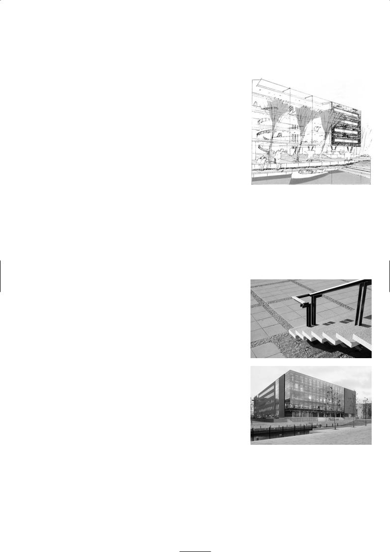
Concept sketch of exterior
Handrail with laminated ash
Main elevation, Tuborg 15 building
152
Concept sketch of atrium and
staircase
View from staircase
Cantilever treads and
curved column profile
153

an integral part of the balustrade. It supports the spiral beam and the landing and carries the loads to the foundations. The balustrade beam spans from floor to floor, between the column. The column restricts the bending and torsion in the balustrade beam. Each staircase step cantilevers as an independent element – we did not allow for any interaction or restraint from the adjacent steps nor for the spread of load in our calculations. In reality the steps and risers help each other and ensure an exceptional rigidity of the construction, resulting in zero deflection at the edge under the worst loading conditions. We designed the floor loading as 2.5kN/m2. The landings are connected to the building floor and provide the lateral stability of the staircase structure.
Every element of the spiral staircase is precast with 100Mpa CRC. The flights – which comprise the balustrade beam and cantilever steps – are cast in four sections and stitched together with in situ JointCast CRC on site. The joints between flight are nominally 80mm wide as the JointCast CRC has an exceptional high bond strength which reduces the joint width. The upper balustrade section connects over the top of the column and links with the landing section. The first flight structure is carefully propped before the upper column element is put in position and the joints then filled.
The main difference between CRC and conventional concrete apart from the increase in compressive and tensile strength, is the superior bond strength and anchorage length that we can work to. We can design with very short lengths of starter and lapping bars, only one fifth of the bond length required for normal concrete. The most critical section was the anchorage length of 100mm required for the rebar of the cantilever steps. Allowing for tolerance and cover this required the balustrade wall to be 150mm wide. The reinforcement takes all the cantilever moment and transfers it to the balustrade beam. Perhaps we could have made the balustrade beam as thin as 100mm and used U bars to develop the anchorage for the steps, but that would have made the joint details with the interconnecting bars of the balustrade beam too complicated. In any case we felt we needed the 150mm thickness to cater for the bending and torsion in the beam.
When we first proposed a column supporting the balustrade beam we suggested it should be square. The architect came up with the idea of making it
150mm thick the same as the balustrade and to curve its width to maintain the Construction of spiral staircase curvature of the balustrade. That was a very elegant solution which we then
detailed.
In all our design work using CRC we had to justify our calculations and assumptions to the checking authorities. We showed them the long-term test results on durability, bending, anchorage, fatigue etc. that CRC Technology had undertaken over 15 years. As regards fire risk, the staircase is not the fire escape stairs for the building and therefore required only a half hour fire rating. The concrete cover to the bars was 15mm (10mm for cover and 5mm tolerance) and we have used 8mm diameter bars in the steps and 16mm bars in the balustrade wall and column.
Final design schematic
P R O J E C T D AT A
Client: Carlsberg Ejendomme
Architect: Arkitema
Engineer: Ramboll
Contractor: NCC Denmark A/S
Completion: 2002
154
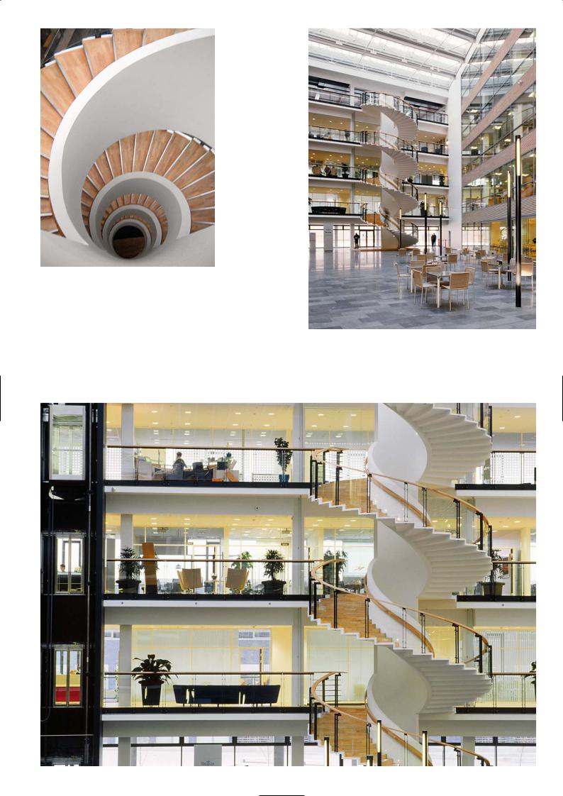
Looking down the spiralling balustrade
Atrium and spiral staircase
Concrete sculptural art
155

Ductal
S E O N Y U F O O T B R I D G E , S E O U L
Rudy Ricciotti, Bandol Architects
Location
The Seonyu footbridge links the Sunyudo Island on the Han River with the city of Seoul. The island has been inaccessible to the public since 1976 but now that it is converted into a beautiful park for the public to enjoy, the footbridge provides the access.
Architectural Concept
Rudy Ricciotti
In Seoul’s broad cityscape considered on the scale of conurbation, structures spanning the river are numerous, while others are still under construction. There are bridges for car traffic whose construction is based on steel or concrete technology. The steel bridges make use of heavy trussed girder construction of 100 years ago. The concrete structures express bridge technology of the 1960s with concrete piers and beam and box girder deck sections. In this context it seemed natural to adopt a more audacious technology.
The scale of the span is the most difficult aspect, for the distance of 120m is too short to make reference to the car bridge structure that brushes the top of the island. It is also too great a span to consider the work from the landscape perspective alone. What is required then is a proposal deftly combining sign and meaning. The first sketches put forward by the city of Seoul showed a suspension bridge in the style of the Golden Gate, breaking both with the scale of the site and the use of modern technology and materials in spanning the river.
It had thus to be a concept that would not rupture the sight line and the narrative of the landscape. The main motif was a taut arch with the slimmest depth over the 120m span.
Its exceptionally sleek proportions are to evoke the smoothness and white colour of porcelain and fragility of an egg shell.
Design and Construction
Mouloud Behloul, LafargeDuctal, France
The Seonyu footbridge, which was built in time for the World Cup in 2002, was called ‘The Bridge of Peace’ when it was opened but has since reverted to its official name. It consists of two steel approach spans and a central arch of 120m made of Ductal®.
Ductal®-FM, with a compressive strength of 180Mpa, was specified for the Seonyu Bridge where high bending and direct tensile strengths are required. These mechanical properties are achieved by introducing short steel fibres 1315mm in length with a diameter of 0.2mm at a dosage of 2% of the mix volume. The application of heat treatment after the mix sets in the mould, eliminates drying shrinkage and greatly reduces creep.
The Ductal® Arch
The 120m arch is connected at each end to massive reinforced concrete foundations which are 9m deep. These foundations are designed to absorb the horizontal thrust of the arch. The arch consists of a ribbed upper deck slab (the walkway) and two girder beams in a double T configuration. The width of deck slab is 4.3m and the beams are 1.3m deep. The deck slab has a 30mm topping with transverse ribs at 1,225mm centres. The depth of the ribs was 160mm for the first and sixth segment and 10mm for the others. The deck slab is supported by the two 160mm thick girder beams. The shape of the girder beams and deck slab geometry was chosen for easy demoulding of the section.
The ribs of the deck slab are prestressed by either one or two 12.5mm diameter monostrands. Specially adapted small anchors were used to transfer the prestressing forces from the strands to the ribs. Each girder beam is prestressed longitudinally by three tendon clusters which are sleeved through metal ducts. There are nine strands in each of the clusters in the lower two ducts and 12 strands in the upper duct. The tendons of the beams are stressed once the segments are in place on the supporting scaffold towers. After completion of the stressing phase, the tendon ducts are grouted. Two temporary monostrands are cast into each segment in the lower part of beam to cater for stresses during lifting and
156
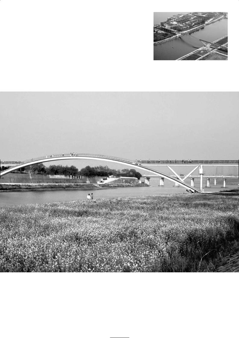
Aerial view
Properties (typical values) of Ductal® with steel fibres
and after heat treatment |
|
Density |
2,500kg/m3 |
Compressive strength |
180 MPa |
Tensile strength |
8MPa |
Post-peak strength in tension |
5MPa |
Young modulus |
50,000 MPa |
Poisson ratio |
0.2 |
Shrinkage |
0 |
Creep factor |
0.2 |
Thermal expansion coefficient |
12.10-6m/m |
157
placing operations as each segment in positioned onto the scaffold towers that were built across the river.
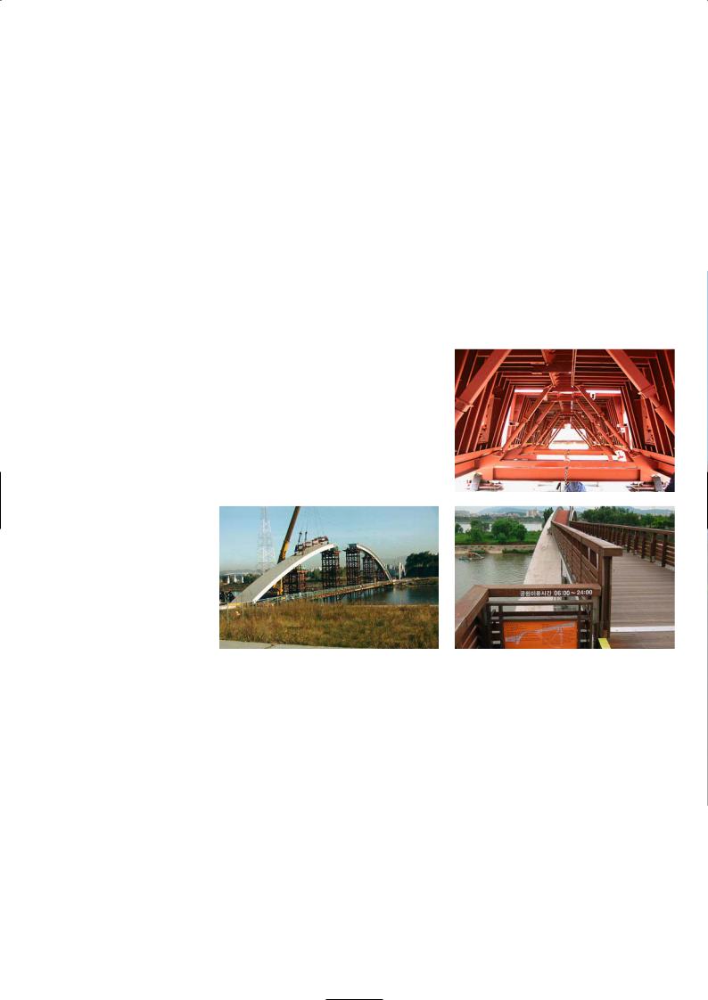
The arch is composed of six segments. These segments are prefabricated in an area next to the final location of the arch. Diaphragms are added at the ends of each segment. The diaphragms on the end segment spreads the compressive loads impacting on the foundation concrete, while those over the central arch are for jacking the two halves of the arch.
The segments are 20-22m long and curved. The slope at the extremities is more than 8%. The volume of Ductal® in a segment is 22.5m3. The total mixing time to fill the metal mould for each segment was 5 1/2 hours. The mould is filled using eight injection points positioned midway along the internal surface of the beams. During the casting operations, the fluidity of the mix is constantly checked and controlled.
After casting a segment, it is cured in the mould at 35° C for 48 hours. A spreader beam is used to crane lift the segment from the casting area to a heat treatment chamber. The segment is then steam cured at 90° C for 48 hours.
The six segments (three on each half of the arch) are positioned in sequence on the scaffold towers by a crane, mounted on a river barge. The segments on each of the half spans are stitched together, then prestressed before the tendon ducts are grouted up. The two half spans are finally joined together by casting the short in situ crown or key segment stitch. Before casting the in situ stitch a
Mould design and mould structure
Left: Erection of arch spans
Right: Footbridge walkway
precompression force of 2,300kN is applied to each half span using hydraulic jacks. The key segment stitch is then cast and when the Ductal® in the stitch has reached a strength of 85MPa, the jack loads are removed and the force transfers back into the arch, to maintain the arch in precompression. This is good for stability and robustness.
Potential vibration of such a slender arch had to be considered. Analysis produced an elegant solution based on shock absorbing tuned mass dampers which limit the horizontal acceleration to 0.2m/sec and the vertical acceleration to 0.5m/sec to maintain crossing comfort level.
This is the first time in the world that an ultra high performance concrete, reinforced with steel fibres has been used for a span of 120m. The properties of Ductal® have made it possible to design a very slender arch with thin sections, giving the footbridge elegance and grace.
P R O J E C T T E A M
Architect: Rudy Ricciotti, Bandol Architects
Contractor and Engineers: Bouygues Travaux Public
Prestressing Work: VSL (Korea)
Lighting Design: Yann Kersale
Completion: 2002
Bridge Dimensions: Length 120m;
height (at mid-span above water level) 15m; depth of section 1.3m; deck slab 30mm; width of deck 4.3m
158
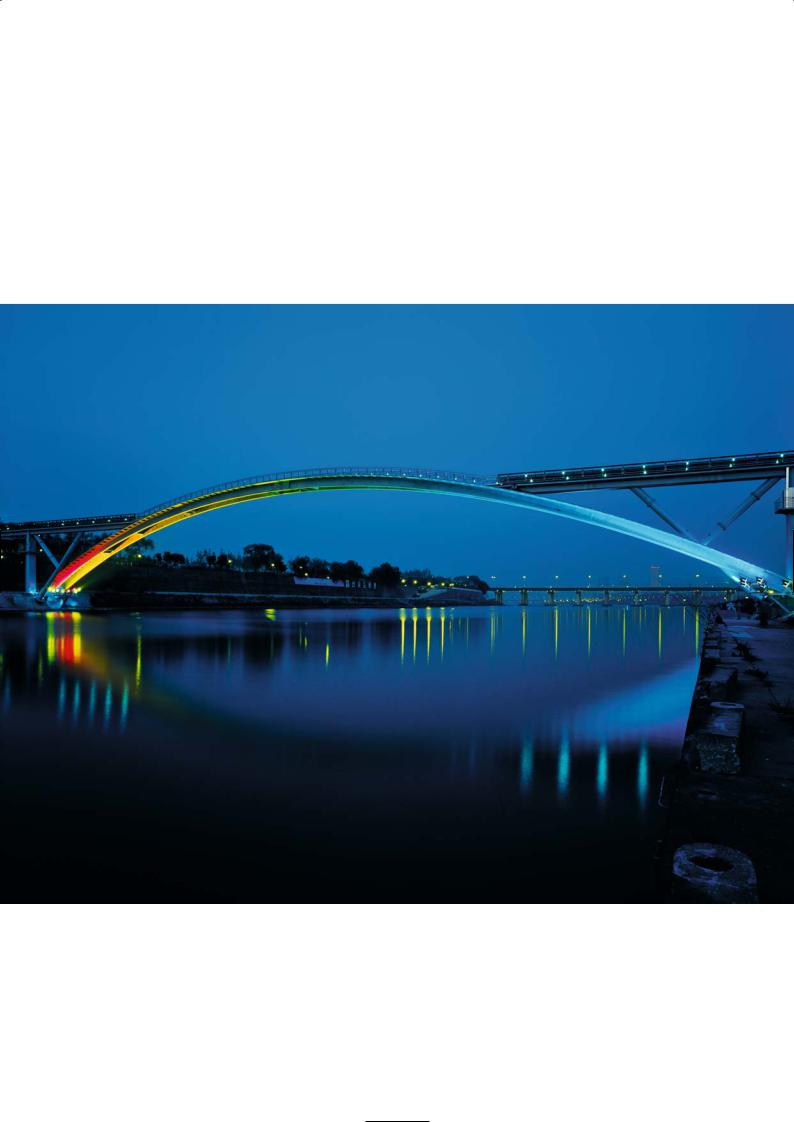
The exceptionally slender proportions of the arch
are accentuated by dramatic lighting
159