


TWO-STROKE ENGINES |
Chapter 19 |
STAR Set-up in es-ice |
|
|
|
STAR Set-up in es-ice
This section describes the required settings in the Star Controls panel, which is where the static meshes for ports are imported and model physics defined. Before attempting this part of the tutorial, it is important that you familiarize yourself with the Star Controls panel by completing the example in Chapter 6 of this volume. In the following sections, most of this panel’s settings are only presented in summary form, but information specific to two-stroke models is described in more detail.
The required Star Controls panel settings are as follows:
1.Analysis setup — load the model into Star Controls and select the desired combustion model
2.Valve lifts — there are no poppet valves, so this Star Controls panel can be ignored
3.Assembly — import the port meshes and create PASIs, with an overlap tolerance to improve solver stability
4.Combustion — specify combustion and ignition parameters
5.Initialization — specify the engine initial conditions
6.Boundary conditions — specify the engine boundary conditions
7.Post-setup — specify the post-processing requirements
8.Time step control — specify the time-step settings
9.Write data — write the files needed to import the model into pro-STAR
Analysis setup
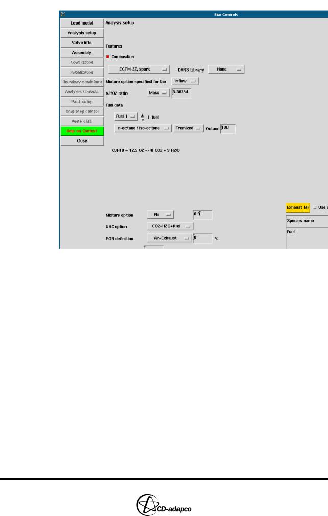
In the Analysis setup view of the Star Controls panel (see Figure 19-17):
•Click Load model
•Check that the Combustion toggle button is selected
•Select ECFM-3Z, spark from the combustion model drop-down menu
•Ensure that the fuel type is set to n-octane / iso-octane
•Set the Mixture option to Equivalence ratio and enter 0.9 for the air-fuel ratio
•Select the Premixed toggle button as the fuel and air are mixed upstream of the intake port
19-16 |
Version 4.20 |
Chapter 19 |
TWO-STROKE ENGINES |
|
STAR Set-up in es-ice |
|
|
Figure 19-17 Two-stroke Star Controls > Analysis setup panel
Assembly
In the Assembly view of the Star Controls panel, import the transfer and exhaust port meshes (see Figure 19-18):
•Click the ellipsis (...) button next to Database file and select twoStrokePorts.dbs via the file browser
•Click the ellipsis (...) button next to Database ID and select 1 Transfer Ports
•Click Get to load the transfer ports into the Controls Workspace
•Click the ellipsis (...) button next to Database ID and select 2 Exhaust Ports
•Click Get to load the exhaust ports into the Controls Workspace
Version 4.20 |
19-17 |

TWO-STROKE ENGINES |
Chapter 19 |
STAR Set-up in es-ice |
|
|
|
Figure 19-18 Two-stroke Star Controls > Assembly panel
Next, create the PASIs and specify an overlap tolerance. Although a port can be physically open, using an overlap tolerance will effectively keep the port closed until the port opening distance is greater than or equal to the overlap tolerance. This facility improves the solution stability by avoiding a situation where a large pressure difference occurs across a very small area.
To create PASIs and set the overlap tolerance (see Figure 19-19):
•In the Star Controls panel, click Create PASI to create the Partial Arbitrary Sliding Interfaces between the cylinder and ports. Note that the current vertex set contains the vertices of the PASI faces
•Select the Overlap tolerance toggle button and set the value to 1
•Click Finish to assemble the model
•In the main es-ice window, click Yes to answer the prompt.
Figure 19-19 Create PASI and overlap tolerance
Combustion
In the Combustion view of the Star Controls panel (see Figure 19-20), enter the ignition time and location.
•Set the Knock drop-down menu to On to activate the knock model
•Set the Spark time to 700 deg CA to specify ignition 20 degrees before TDC during the first cycle
•Set the Location XYZ to 0, 0, 29 to define the first ignition location
19-18 |
Version 4.20 |

Chapter 19 |
TWO-STROKE ENGINES |
|
STAR Set-up in es-ice |
|
|
Figure 19-20 Two-stroke Star Controls > Combustion panel
Initialization
In the Initialization view of the Star Controls panel, set the engine initial conditions as described below.
For the Cylinder (see Figure 19-21):
•Check that Cylinder is selected from the domain drop-down menu
•Set the Valve function to Intake
•Set the Pressure to 3 and select bar from the drop-down menu
•Set the Temperature to 1000 K
Version 4.20 |
19-19 |

TWO-STROKE ENGINES |
Chapter 19 |
STAR Set-up in es-ice |
|
|
|
Figure 19-21 Two-stroke Star Controls > Initialization panel for the cylinder
For the Grid Pieces, there are seven regions that correspond to each of the transfer and exhaust ports.
First, set the initial conditions for the transfer ports (see Figure 19-22):
•Select Grid Pieces from the domain drop-down menu
•Check that Region 1 is selected and then set the Name to Transfer Port 1
•Set the Pressure to 1.3 and select bar from the drop-down menu
19-20 |
Version 4.20 |
Chapter 19 |
TWO-STROKE ENGINES |
|
STAR Set-up in es-ice |
|
|
Figure 19-22 Two-stroke Star Controls > Initialization panel for Transfer Port 1
•Select Region 2 from the drop-down menu
•Set the Copy data of option to Region 1 so as to use the same initial conditions as Region 1 (see Figure 19-23)
•Reply Yes to the prompt to confirm the use of Region 1 parameters
•Set the Name to Transfer Port 2
•Repeat the previous four steps (with appropriate names) for Region 3 and Region 4, as they are also transfer ports
Figure 19-23 Two-stroke Star Controls > Initialization panel for remaining transfer ports
Next, set the initial conditions for the exhaust ports (see Figure 19-24):
•Select Region 5 from the drop-down menu
Version 4.20 |
19-21 |