

Attachment Installations
Article 24. Expansion Joint
An expansion joint shall be attached at a place where an excessive stress or deformation is liable to be generated in an axial direction by a temperature change or other external forces.
An expansion joint shall be strong enough and watertight, and be of- such structure as to exert its function thoroughly over expansion and contraction.
The range of temperature changes for steel penstocks used for calculating the expansion length shall be determined taking account of max. and min. temperatures at site.
As for the length of a slide type expansion joint, more than 5cm al-
’ lowance shall be given to a calculated value.
Description:
The temperature of a steel penstock with water in it is mainly influenced by water temperature, and governed by ambient temperature when the penstock is empty, and is affected by sunshine when exposed. A main, purpose of an expansion joint is to enable a penstock to expand in an axial direction depending on this temperature change so as not to generate excessive stresses, and this joint also helps adjusting the length of a pipe when installed.
An expansion joint generally used is of a sleeve type which enables a pipe to expand only in an axial direction, and the joint is usually installed just downstream of an anchor block or in the middle of both anchor blocks for almost a horizontal pipeline in view of installation
* convenience.
When a penstock is placed through two structures which are expected . a relative displacement, it is necessary to attach an expansion and deflection joint allowing a move both in an axial direction and in a normal to axis direction.
For such a joint a sleeve coupling type is used.
A sleeve type expansion joint is of structure to insert the leak prevention packing into a stuffing box between two pipes, i.e. internal and external sleeves, and to press the packing with a packing gland, as illustrated in Fig. 1.24-1. Four to eight square flax strings with grease thoroughly permeated and one or two round rubber packings are usually used as packing. An internal sleeve should be designed so as to resist an external pressure by the packing. As a sliding portion of the internal and external sleeves is liable to generate rust due to coating inapplicability, it is desirable to use a stainless clad steel on the outside of an internal sleeve or to apply a metalikon process so as to prevent corrosion and make sliding better.
Square flax packing
_i. '-.OTb—y/ Round rubber packing —rPr—
,'T1 1
Sleeve
coupling type
Square
flax packing
r pr? *-■.
\ / Round rubber packing
Sleeve
type
Fig.
1.24-1 Example of Expansion Joint


![]()
A slide distance I of an expansion joint due to temperature change is given by the following formula:
/ = LaT
where L: Distance between anchor blocks
a : Coefficient of linear expansion = 0.000012/°C
T : Temperature change (°C)
The range of temperature changes in penstocks used for the above formula should be decided taking into account the highest and lowest temperatures at site. A penstock temperature under direct sunshine with no water in it reaches as high as 60°C, thus requiring attention to be paid. As for the highest temperatures for the above penstock i.e. under direct sunshine and with no water in it, various observation data have been reported, and the following empirical formula is presented:
27
where
T:
Max. temperature of ah empty penstock under direct sunshine (°C)
Ambient temperature (°C)
In case of an empty penstock under direct sunshine, one of the examples of paint effects on the penstock temperature is shown in Fig. 1.24-2.
Fig.
1.24-2
Example
of Temperature Observation on Empty Penstocks under Direct Sunshine


As for an allowance of a slide type expansion joint, it is specified to be more than 5 cm longer than the calculated value from the previous formula, taking account of structural safety and adjustment of installation.
Article 25. Manhole
A manhole necessary for maintenance and inspection shall be attached to a steel penstock, taking its length, diameter and gradient into consideration.
The manhole shall be of ellipse type, having a 450mm major axis and a 350mm minor axis, or circle having a 450mm internal diameter.
Description’.
A steel penstock requires a manhole for maintenance and inspection,
. and the number of manholes are dependant upon the penstock’s length, diameter and gradient. Manholes are usually spaced 120 to 150 meters apart. The location of a manhole is principally determined so as to gain an easy access and usually to be at the top or lower sides.
In Japan, a manhole either of an elliptical shape with a 450mm major axis and a 350mm minor axis or of a circular shape with a 450mm in- ’ ternal diameter is usually employed but the size about 400 x 300mm is also used for a less than 1.0m diameter penstock.
The plate thickness of a manhole cover can be given from the following formula, by assuming that the cover is an elliptical flat plate subjected to distributed loads under the edge free support.
t = b\ + e
X a
where t: Cover thickness (cm)
b : 1/2 the minor axis (cm)
p : Internal pressure (kgf/cm2)
cr: Allowable stress of steel plate (kgf/cm2)
c: Corrosion allowance (cm)
K: Stress concentration coefficient
Coefficient K is provided in Table 1.25-1 based on S. Timoshenko’s theory:
Table 1.25-1 Stress Concentration Factors
a/b |
1.0 |
LI |
1.2 |
1.3 |
1.4 |
1.5 |
K |
1.24 |
1.41 |
1.57 |
1.69 |
1.82 |
1.93 |
a: 1/2 the major axis (cm)
K 1.7 for ellipse of 450 x 350mm
A rubber packing is usually used for the manhole.
It is desirable to attach chains to the cover so as not to fall inside the penstock when the cover is removed.
With a high water pressure, the cover plate for an elliptical manhole >• gets thick, and so opening and closing becomes difficult. Thus, a cir-... cular manhole, as illustrated in Fig. 1-.25-1, has been employed.
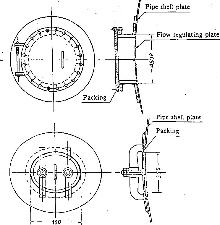
Fig. 1.25-1 Example of Manhole
' . i
Article 26. Air Pipe and Air Valve
An air pipe or an air valve capable of keeping the pressure difference inside and outside the penstock less than 0.2kgf/cm2 during the water discharge shall be installed.
In case of a possible freeze of an air pipe and air valve in a cold sea
son, or in case of clogging of the above with leaves, etc., an effective measure to protect a discharging function shall be provided.
Description:
1. The purpose of an air pipe or an air valve is to discharge air when filling water into the penstock and to release air into the penstock when- discharging water, and this is the most important device for the prevention of crushing during water discharge.
In case that the pressure difference is likely to exceed 0.2kgf/cm2 when the internal pressure of the penstock becomes lower than the external atmospheric pressure during water discharge, an air pipe or an air valve shall be installed which is activated at a pressure less than 0.2 kgf/cm2. If a pipeline is higher than the hydraulic gradient line at a horizontal or almost horizontal portion of a penstock, there are some examples that an air pipe or valve is also installed downstream at that portion. This is to prevent negative pressure produced in a penstock due to a sharp loading change in addition to filling and discharging water.
Limit switch /
Opening
speed regulating valve
I
Piston

Watertight rubber / Watertight seat
‘ Jet flow deflecting plate
Fig. 1.26-1 Typical Type of Air Valve
The minimum intake sectional area of an air valve is given by the following formula:
where A : Min. intake sectional area (m2)
Q: Max. discharge inside the penstock (mJ/s)
AP: Allowable pressure difference (tf/m2) y„: Specific weight of air (0.001226tf/m’) g : Acceleration of gravity (9.8 m/s2) C:-Discharge coefficient of air (normally 0.6)
2. As an air pipe or air valve may probably be frozen in cold areas, it is necessary to protect it from freezing by using various measures such as electric heating, pressing in grease, etc. Attention should be paid so that no foreign matter enters when closing these devices, and careful provisions for protection should be arranged in cases where an air pipe or valve may be clogged with leaves and snow.
An air valve is subject to an impact in closing and opening, and thus it should be strong enough to resist the impact.
’ In addition to the above consideration, it is advisaW to install two or more air valves so as to ensure safety against an unexpected accident for the purpose of increasing reliance on workability of the valve.
Article 27. Anchor Bolt, Anchor Band, Thrust Collar
1; At the place of an anchor block where an upper portion of a steel penstock is exposed or when a tensile stress is generated in an anchor block with a thin concrete cover, a penstock shall be fixed against an external force by means of anchor bolts, anchor bands or other devices.
2. At a place where a steel penstock is fixed into an anchor block or embedded in a tunnel, anchor bolts, anchor bands or other devices shall be used to cope with buoyancy acting on a penstock when the concrete is filled, and a thrust collar shall be used to deal with the axial force.
Description-.
In many cases, an anchor block is installed at a bend pipe portion. External forces in this case acting on an anchor block are those listed in Article
55., of this Chapter. In order to fix a penstock to an anchor block, this should be structured so as to transmit these external forces enough to an anchor block. In particular, when a fixed bend pipe is convex upward and an outward force is big, or when an upper portion of the pipe is exposed, or when excessive tensile stresses take place in concrete with a thin concrete cover, it should be designed so as to transmit an external force directly to an anchor block.
A thrust collar should be installed to cope with an external force acting in an axial direction.
For an anchor block placed at a bend pipe which is not convex upward and for a tunnel embedded pipe, an outward force does not act but a buoyancy acts on a steel penstock when concrete is filled, and thus it is necessary to protect an installed pipe from displacement or deformation by means of an anchor bolt or an anchor band.
Allowable bond stresses of an anchor bolt embedded into concrete arjs listed in Table 1.27-1.
Allowable bearing stresses of concrete should be less than 0.3acJt (28 days design standard strength of concrete). The strength of concrete differs from ratio of water to cement, strength of cement and aggregate, curing, etc., and so its stress value should be decided depending on work executing conditions.
|
180 |
240 |
300 |
£400 |
. Round bar |
7 |
8 |
9 |
10 |
Deformed bar |
14 |
16 |
18 |
20 |