

It: Moment of inertia of stiffener (cm4)
In addition to the above, R.C. Sturm’s formula, A. Fliigge’s formula, etc., may be used.
B. Stiffeners
E. Amstutz’s formula is generally used.
E. Amstutz’s formula ’
=
1.68-^-^^
e
Es
rm
Of—an![]()


where /: Radius of gyration of combined section of stiffeners (cm)
e: Distance from the center of gravity of a combined- section of stiffeners to internal surface of the pipe (cm) •
^o = O, by grouting, etc., and when the initial compressive stress crv is acting on stiffeners, —should be applied in place fa . ' •
of in the first term of the equation.
rm
With <jn given from the above formula, the critical stress acr is given by the following equation:
/p* Of-~O'N '
e I. 3 i+yxE,.
In this case, when the average compressive stress of stiffeners is ac.
p'rp' (tr+ 1.56jr~7)
~ So+ 1.56tjrmt >.
i
Effective width I
a?s^t
•• r
Fig. 1.16-7 Embedded Pipe with Stifferers
 p'
is the modified value of external pressure p
summing up shearing forces acting on both sides of a stiffener from
a pipe shell.
p'
is the modified value of external pressure p
summing up shearing forces acting on both sides of a stiffener from
a pipe shell.
rQ -
2r0'2
Accordingly, the safety factor S/ against buckling in this case can be expressed as follows:
crf
Article 17. Corrosion Allowance
For thickness of plates used for a pressure lining part, an allowance of more than 1.5 mm shall be provided against corrosion and wear. The corrosion allowance may be reduced provided an appropriate measure be taken against corrosion an$i wear in particular.
Description:
When steel penstocks are used for many years after installation, their shell thickness decreases from inside and outside of the pipes due to corrosion and wear. Thus, in order to secure a safety factor and to increase the life of the steel penstocks, an appropriate allowance should be introduced in designing.
Since a decrease in thickness is developed physically and/or chemically, the corrosion allowance should be decided taking account of the level of incoming soils and sands, influence by water quality, velocity of flow and
There are no data available to determine the amount of the corrosion allowance quantitatively, but Section VIII of ASME Pressure Vessel Code for Boilers specifies more than 1/6 of the calculated plate thickness (but for less than 6mm thick plates), and JIS B8243 (1977) Construction of Pressure Vessels specifies more than 1mm, and thus 1.5mm is set in this standard taking various elements into consideration.
In recent years, however, paints and coating techniques have made remarkable progress, and such anti-corrosion technique as metal spraying in addition to coating has also been employed to some extent, and thus it is not always required to have a 1.5mm allowance prpviding an appropriate construction technique and special materials be employed. Thus, the allowance in this case may be reduced.
Article 18. Minimum Shell Thickness
Minimum shell thicknesses used for the pressure lininjppart shall be more than those determined from the following formula if stiffeners are not used. The minimum shell thickness shall not be less than 6mm even if the pipe' diameter is small and stiffeners are used.
- = D + 800
‘ 400
where t: Shell thickness including corrosion allowance (mm)
D: Internal diameter of pipe (mm)
Description :
The shell thickness at the pressure lining part is governed mainly by the circumferential stress caused by the internal pressure, and furthermore the thickness is decided taking account of the longitudinal stress and the corrosion allowance also. However, the internal pressure is generally low at an upstream portion of a steel penstock, and if the shell thickness is determined only by the circumferential stress caused by the internal pressure, the thickness would be a very small one. Thus, it is necessary to regulate a minimum thickness only to keep the rigidity required for such conditions as manufacture, transportation, installation and so forth.
The Bureau of Reclamation specifies the minimum shell thickness obtained from the following formula as an empirical one, taking manufacture, transportation, installation, etc., into consideration:
= + 508
/min 400 ■
where /min: Minimum shell thickness (mm)
D: Pipe diameter (mm)
Pacific Gas & Electric Co. has determined the minimum shell thickness by using the following formula:
'min 288
This formula is obtained by substituting a critical external pressure Pk = 0.2 kgf/cm2 from a condition to resist crushing by the external pressure of pipes withdut stiffeners, i.e. in
' 2E //V
Pk~ 1-p2\d)
In
this Article, it is specified to determine the minimum shell
thickness from t
- &
jpg
by t^^rring t0
these two formulae and by taking account of empirical
practices, of manufacture, transportation, installation, etc.,
in Japan. A thin pipe, compared with the pipe diameter is liable
to have an excessive flatness of a pipe section with water fully
filled and generate vibration due to a hydraulic pressure change.
This also requires attention? - h
' However, this is a minimum shell thickness when a penstock has no stiffeners. In case that the shell thickness is not determined by the internal pressure but by the external pressure (concrete pressure, grouting pressure during! a construction workandhydraulic pressure on the surface of penstocks) for some ejnbeMle^^a^liJi may be better economically to provide a safety against buckling by attaching proper stiffeners rather than just a pipe shell plate. In such a case, it is permissible to use plates thinner than those from this formula provided stiffeners are sure to prevent pipe’s deformation and do not have any trouble in manufacture, trans- z poriadon, and installation.
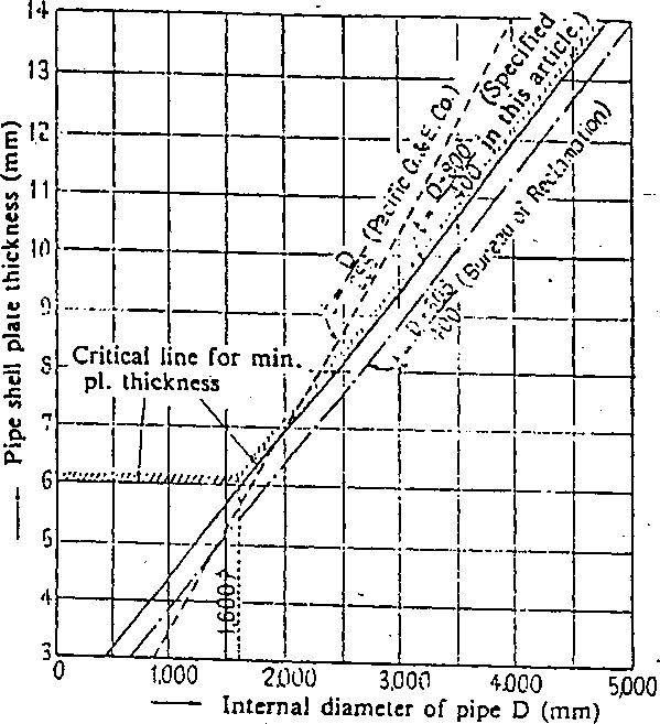
Fig. 1.18-1 Determination of Min. Shell Thickness
The reason for setting the minimum shell Sickness at 6mm even if the pipe diameter is small, is that in Japan the minimum thickness has been regulated from the past actual results and welding practice, etc.
'Article 19. Coefficient of Friction between Pipe and Supports Coefficient of friction between pipes and supports, used for design shall be more than those specified in Table 1.19-1.
Table 1,19-1 Coefficient of Friction
Type, of bearing |
Friction factor |
Concrete bearing Concrete saddle having sliding supplement Slide bearing Rocker bearing Roller bearing |
0.60 0.50 0.25 0.15 0.05 |
Description :
A steel penstock expands and shrinks due to the temperature change, which generates friction between a pipe and a support, thus in turn, resulting in a longitudinal stress generated.
The stress in such a case differs greatly depending on type of bearings.
Coefficient of friction should be decided by taking actual measurement results into consideration, but in Japan there are not so many measurements available, and thus the values from the Bureau of Reclamation are employed.
As for roller bearings, the values are derived from those shown in Specifications for Highway Bridges and its Description written by Japan Road Association.
A rocker bearing referred to in this Article is the one specified in Article 28. of this Chapter, and a roller bearing is the one which generates only a rolling friction.
Article 20. Effective Sectional Area of Pipe Shell Plate
The effective sectional area of a pipe shell plate used for the design calculation shall be determined from the following formula:
A = tt(/0- e)Dm
where A: Effective sectional area of pipe wall (cm2)
Zo: Pipe thickness when manufactured (cm)
e: Thickness allowance against corrosion and wear (cm) Dm: Diameter to the center of plate thickness (cm)
Description:
When designing the stress of a steel penstock, the effective sectional area for a pipe shell plate is often required.
The effective sectional area is to be determined by subtracting a thickness allowance against corrosion and -wear from the shell thickness, and .as is shown in Fig. 1.16-1, Article 16. of this Chapter, it is set that the thickness allowance should be taken as e/2 each from both the internal surface and the external surface of the pipe shell plate.
Article 21. Bend Pipe
The radius of curvature for a bend pipe shall be more than three times the pipe’s internal diameter and intersecting angle of each unit pipe shall be less than However, 90° bend pipe, branch and in other unavailable cases, their radius of curvature may be more than twice a pipe’s internal diameter.
Description:
♦
A
bend pipe is required at a place where the direction of penstocks
changes, and it is hard to construct a pipe in a smooth arc shape,
and so a bend pipe consisting of oblique joints for each unit pipe
is constructed. There are many test reports on relation between
radius of curvature of a pipe center line (R), an internal diameter
(d)
and loss of head. And according to the values adjusted and reviewed
by Anderson and Straub the loss factor gets small simply with the
increase in
R/dt
and gets further smaller with more than three in R/d.
With an excessive increase in R/d,
however,
the bend pipe length gets larger and it cannot be economical.
romiuah-
Since there may be no space available to take a proper radius of curvature for 90 degrees bend pipe and a branch etc., it is specified in such a case that the radius of curvature may be more than twice the inside diameter of the pipe as an alleviation regulation.
It is considered that the less an intersecting angle for each unit pipe is, the smoother bend pipe can be obtained, and thus an actual loss of head decreases. Accordingly, in this standard, an intersecting angle is set at less than 7 degrees which has been regarded as appropriate so far from workability and economic viewpoints. However, it is desirable to set at approximately 4 to 5° when keeping of a waterhead is very important for a power station having a low waterhead and a large capacity.
In planning steel penstocks, design is in many cases made so that a horizontal angle and a vertical angle take place at one point.in order to minimize bend pipes which cost much. In this case, the combined angle of the horizontal and vertical angles is determined from the following formula:
Fig.
1.21-1 Combined Angles for Steel Penstock (
For
a positive sign (+) For a negative sign (-)
Profile Plan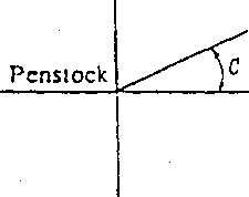
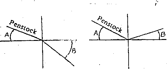


cos X = cos A cos. B cos C ± sin A sin B
where X: Combined angle on the plan including a penstock upstream and downstream of a bend
A, B, C: Angles shown in Fig. 1.21-1.
Negative sign (-) means the case both A and B direct upward.
.. Positive sign ( + ) means the case A and B direct upward
and downward alternately.
- In orddr to reduce the number of bends and reducers, reducing bend • pipes are often used by compounding bend pipes and reducers. In design for reducing bend pipe, there are the following two methods.
(1). In case that each unit pipe is structured with a reducer
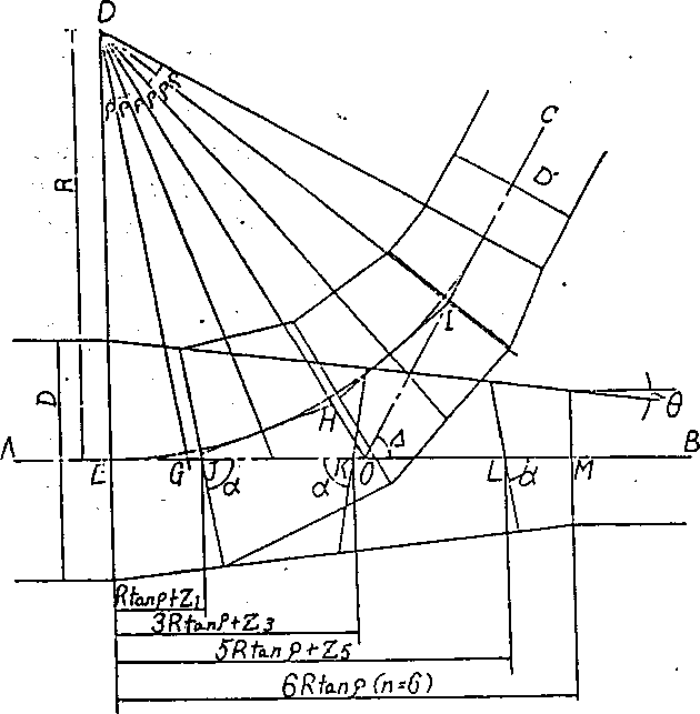
Fig. 1.21-2 Diagramming of a Reducing Bend Pipe
2n R tan q D
Rx = ——x R tan q tan d
cos2 q
A: Intersecting angle a = 90° - q
R: Radius of curvature
I = n R tan q (length of a reducer) •
n: Number of equipartition of d (even number)
D: Internal diameter of a larger pipe
D' : Internal diameter of smaller pipe
(2)
In case a starting unit pipe and an end unit pipe are structured
with
sin
0== , _ _
2(n-2)7?
tan q
<i
2 r"~
2
,
sin 2o .
tan 6 = ;—
cos
2q
+ cos
0 2 fl
G
•
1
cos 2q
+ cos 0 rn
sin 0
cos
2p + cos 0 rx
sin 0
COS
Q
R:
nt


4
e=7
= n - (x - 1)R tan q sin 0
Di-2(x-l)R tan q sin 0
cos 0
Intersecting angle Radius of curvature
Twice number of intersecting point
Internal diameter of a larger pipe
Internal diameter of a smaller'pipe ,
Number of divisions from the center line of the steel penstock to the desired point
Article 22. Branch
Branch shall be of a structure to be safe against internal and external pressures acting on itself, and sufficient attention shall be directed with respect to flows Of water. . .
Description: J
1. Type of Branch
A penstock is generally called a branch where the flow of water is to be divided into two or more, or where two or more flows of water are to be gathered to a main pipe.
There
are sey^altypesof branches, bifurcation and trifurcation aijuj so
on. A s
![]() bifurcation
is generally employed. In case
bifurcation
is generally employed. In case
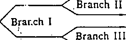
of branching into 3 of more as is shown in Fig. 1.22-1 (1), the fol-' lowing types are available: a type of a main pipe to be directly trifurcated, a manifold type in which pipes are branched in the same direction in succession from a straight main pipe (Fig. 1.22-1 (2)), and a type to combine bifurcations (Fig. 1.22-1 (3)).-
c
<u
Main
pipe £
Turbine
Turbire
(1)


Turbine
Main pipe Branch I Branch II
Turbine
Turbine Turbine
1
urbine
■.
Turbine (3)
t
Fig.
1.22-1 Type of Branch
![]()


(2) Structural Classification
A wyc branch and spherical branch are of tyoical ones in struc-
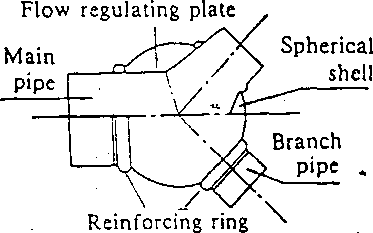
ture of branch. A wye branch is a type to diverge a main pipe to two branch pipes, attaching stiffening girders on their intersecting lines (Fig. 1.22-2), and a spherical branch is a type to connect a main pipe and branch pipes to a spherical shell through reinforcing rings. (Fig. 1.22-3)
Fig.
1.22-2 Y (Wye) Branch
Fig.
1.22-3 Spherical Branch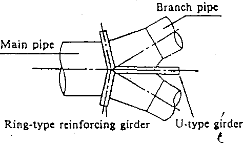


|
1 |
1 1 |
i i |
|
|
|
(3 Wye branch Cl Spherical |
|
|
|
1 |
I |
0 1 |
|
|
oral X Other typ t |
jcn ►es |
|
1 |
1 |
i 1 |
i 1 |
|
|
|
|
|
i |
|
i $ |
» c ‘ |
|
|
l |
|
|
1 |
|
|
|
|
|
|
|
|
|
i |
. i |
|
|
|
- 1 |
|
|
•. • * |
> |
|
|
|
1 |
i I |
|
• • |
o • < 0° c |
== |
|
c |
|
i |
1 |
|
|
•• |
•. * o V |
• o |
- ♦ - |
|
0 |
1 I . |
|
|
|
— |
• • |
• • |
|
• °l ° |
La |
I . i |
fCOO
900
CCO
TC4
400
SCO
KO
oeo
KO
,<3O
.2P
J
* S
i f & 9 to
Diameter
of main pipe (m)
Fig. 1.22-4 Actual Results of Branch Pipes Employed in Japan
H ,7£» SKkc-ycfi t fifct'M-1''-•
- 66 - ‘
/
In case of a wye branch, a U-type girder is treated as a beam subjected to bending, and thus its girder height increases rapidly with an increase in the design pressure. On the Other hand, as a spherical branch is normally treated as an axis symmetrical shell, its analysis is easier compared with that of a wye branch, and it is possible to decrease the local bending stress of a spherical shell connected to a reinforcing ring if its cross section is properly selected. This causes the plate thickness to be less-in comparison with a wye branch.
Such a reason has made a spherical branch employed in almost all penstocks having large capacity and high waterhead as the actual results in .the past show in Fig. 1.22-4.
The loss is larger when spherical branch is used without a flow ' regulating plate compared with that of a wye branch from a hydraulic viewpoint, and thus it is normal to use a flow regulating plate inside the spherical shell, aiming at reducing the loss.
2. Design of branch
(1) Wye branch
Wye branch has a U-type girder attached on the intersecting line • of two branch pipes divided from a main pipe. (Fig. 1.22-2)
A U-type girder is placed in position so as to resist a force acting on the intersecting line of the branch pipes. A ring-type reinforcing girder is to prevent deformation of the U-type girder. In determining a load acting on a U-type girder, it ought to be considered whether or not concave covers exist.-The following consideration is based on a condition without concave covers, i.e. axial tensile force of branch pipes do not act.
The tangential force (T) is shown in Fig. 1.22-5. Decomposing T into three directional components, x, y, and z, they will be as follows:
T= pr. --cos a dx (1)
cos2 6
Tx
=
py
sin a
cos2
0
cos
a
dx
(2)


(3)
(4)
Moreover, the following forces in x and y directions act on a U- type girder due to an internal pressure working on the breadth B of a U-type girder.
Px = pBdx (5)
P, = pBdy (6)
There is a convenient method to consider just an upward force, •' i.e., Ty and Py.
Fig.
1.22-5 Components of Tangential Force Acting on a U-type Girder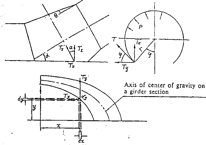

The design on a safe side can be secured by deciding a sectional area of a reinforcing girder in this way. And 6 is generally small and so it is permissible to assume cos20 = 1.
' After determination of the load acting on a U-type girder, a solution should be started by assuming that a U-type girder and a ring-type reinforcing girder connected to the former shall be one structure. In this case, as is illustrated in Fig. 1.22-6, it is assumed that a U-type girder and a ring-type reinforcing girder are connected with a pin. In other word, a ring-type girder is generally of I- or T-shaped cross section, and it is permissible to assume that a ringtype girder does not resist a bending moment from a U-type girder and to assume it as a’pin. Accordingly, a model of reinforcing girders can be shown as in Fig. 1.22-6.

Fig. 1.22-6 Analysis Model for Reinforcing Girder
If the statically indeterminate force X acting on the pin of reinforcing girders is determined, it is possible to solve a ring-type reinforcing girder and a U-type girder respectively, i.e. a reinforcing girder is a primary statically indeterminate structure externally. From the condition that the displacement at an %-acting point on a ring-type reinforcing girder is equal to the displacement at an X-acting point on a U-type girder, it is possible to solve Xas follows:
The displacement of 5R in the X direction at an X-acting point on a ring-type reinforcing girder is:
bR ~ &Rp + (7)
where 5^: Displacement due to internal pressure p
8rx: Displacement due to X = 1
The displacement of in the X direction at an JV-acting point on a U-type girder is:
&u ~~ ^up ~~ (8)
where dUp: Displacement due to internal pressure p bux'. Displacement due to X = 1
Say bR = X can be determined,
(9)
^Rl &UI
With X determined, a U-type girder and a ring-type reinforcing girder can be solved respectively, and then a cross section is decided. As the girder height gets larger around the top of a U-type girder (point C in Fig. 1.22-6) it is necessary to study the buckling of its web plate. In case that a whole branch pipe is embedded, it is necessary to examine the external pressure also.
This Description refers only to the case in which concave covers , are not used and axial tensile forces do not work, but when a - hydraulic test is executed with concave covers, consideration on axial forces is required.
(2) Spherical branch
When a model consisting of a sphere and a cylinder having concave cover as Fig 1.22-7 is considered;
The axial tensile force of a cylinder is:
(10)
■2
The horizontal component of a sphere’s membrane tensile force pr/2 is:
Ohs = -y" cos0 = -y- (H)
Thus, the horizontal direction force is kept balanced with a//c — aHS-
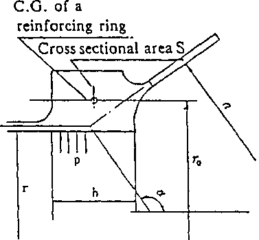
Fig.
1.22-7 Forces Acting on a Connecting Point of Sphere and Cylinder

On the other hand, a reinforcing ring is attached so as to resist the vertical component au of a sphere’s membrane tensile force as illustrated in Fig. 1.22-8.
Fig.
1.22-8 Reinforcing Ring for Spherical Branch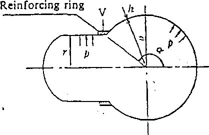

The tensile force 7\ generated in a reinforcing ring by the internal pressure acting on the reinforcing ring’s breadth b is :
T, = prb (12}
The tensile force T2 generated in a reinforcing ring by the vertical component of a sphere’s membrane tensile force is:
T2 = ~^pr0 a cos a (13)
Supposing only the membrane tensile force acting oh a sphere, i.e. a sphere under membrane stress condition, the cross sectional area S of reinforcing ring is:
S = ?' + T> = -^—(br+0.5 r0 a cos a) (14)
arQ or0
where or0: Tensile stress of reinforcing ring
This formula includes the stress of a reinforcing ring arOt but it is possible to determine the formula which does not include ar0 from a displacement boundary condition as follows:
The radial force V acting on a reinforcing ring is:
(15)
V = pb + ~a cos a=p d + —cos a z* \
Then, the displacement 5r of a reinforcing ring in radial direction is:
(16)-
— V —p i + ycosa
The displacement 6, of a sphere in radial direction at connecting point with reinforcing ring is;
FOR 1
Chapter 1 STEEL PENSTOCKS 7
Section 1 General 7
Section 2 Design 4
Description, 19
2. Material and Allowable Stress 31
Description: 31
3. Pressure Lining Part 46
P‘=2-59£-7&: . 48
(cwlT+U^V.- 51
Description: 56
4. Attachment Installations 91
Description: 97
Section 3 Manufacture 101
Section 4 Installation 107
Section 5 Maintenance 119
Section 6 Anchor Block and Support 127
Chapter 2 HYDRAULIC GATE 137
Section 2 Outline of Design 153
2. Gate Leaf, Gate. Guide and Anchorage 162
Description: 196
Description: 201
3. Gate Hoist 201
Description: 202
Description: 205
Description: 206
Description: 206
Description: 210
Section 3 Design Particulars 213
1. Fixed Wheel Gate 213
Description: 223
—~p 223
F=p.r(q + Pb)Ll 224
2. Radial Gate 225
Description: 225
Description: 226
Description: • 1 228
3. Long Span Gate 229
Description: 221
4. Bottom Hinge Flap Gate 222
Description: 222
Description: 224
5. High Pressure Gates and Valves 226
Description: 226
Description: 229
6. Selective Water Withdrawal Equipment and Surface Water Withdrawal Equipment 235
Description: 235
Description: 236
Description: 236
7. Trash Rack 240
Description: 241
Section 4 Manufacture 245
Description: * 245
Description: 245
Section 5 Installation 246
Description: ' ' : ''f. .1.... ' .a? a ' 247
Description: 247
Description: 248
Description: 254
Description: 256
Section 6 Inspection 257
Description: 258
Section 7 Maintenance 259
Description: 259
Description: 259
Description: 259
Description: 260
Description:. - 260
Description: 261
Description: 261
Description: 262
Description: 262
. Chapter 3 STEEL STRUCTURE 269
Description: 269
Description: 269
Section 2 Design 269
Description: 270
Description: 270
Description: 270
Description: - ■ ' 271
Description: 273
Chapter 4 WELDING 274
Section 1 General 274
Description: 274
Description: - 277
Description: 292
Section 2 Welded Joint 296
Description: 296
Description: 289
Description: 293
Description: ".'A • 295
Description: 297
Description: 298
Description: ; ■ 300
Section 3 Welding Procedure 302
Description: 302
Description: 305
Description: 307
Description: 308
Description: 309
Description: 309
Description: 311
Description: 313
Description: 313
f 313
Description: 315
Description: 323
Section 4 Heat Treatment 327
Section 5 Test and Inspections 334
» Description: 335
Description: 336
Chapters 340
RIVETED, HIGH STRENGTH BOLTED AND BOLTED CONNECTIONS 340
Section 1 General 340
19. Description: 358
79. Description: Omitted 352
81. Description: Omitted 352
84. Description: Omitted 352
111. Description: 354
193. Description: 359
198. . Section 4 Bolted Connections 361
217. Chapter 6 SAFETY AND SANITATION 365
The sphere’s plate thickness h is, saying the sphere’s membrane tensile stress rri0
pa
(19)
While, a cylinder’s plate thickness t is to be determined only by the tangential stress with no consideration given to the reinfor- ' cing ring’s effect:
(20)
If t' is to be determined so that the radial displacement 6C of a cylinder may be equal to the radial displacement 6r of a reinforcing ring, it is not required to consider the effect of a cylinder bn
a reinforcing ring and the sphere, and the sphere can be kept under a membrane stress.
FOR 1
Chapter 1 STEEL PENSTOCKS 7
Section 1 General 7
Section 2 Design 4
Description, 19
2. Material and Allowable Stress 31
Description: 31
3. Pressure Lining Part 46
P‘=2-59£-7&: . 48
(cwlT+U^V.- 51
Description: 56
4. Attachment Installations 91
Description: 97
Section 3 Manufacture 101
Section 4 Installation 107
Section 5 Maintenance 119
Section 6 Anchor Block and Support 127
Chapter 2 HYDRAULIC GATE 137
Section 2 Outline of Design 153
2. Gate Leaf, Gate. Guide and Anchorage 162
Description: 196
Description: 201
3. Gate Hoist 201
Description: 202
Description: 205
Description: 206
Description: 206
Description: 210
Section 3 Design Particulars 213
1. Fixed Wheel Gate 213
Description: 223
—~p 223
F=p.r(q + Pb)Ll 224
2. Radial Gate 225
Description: 225
Description: 226
Description: • 1 228
3. Long Span Gate 229
Description: 221
4. Bottom Hinge Flap Gate 222
Description: 222
Description: 224
5. High Pressure Gates and Valves 226
Description: 226
Description: 229
6. Selective Water Withdrawal Equipment and Surface Water Withdrawal Equipment 235
Description: 235
Description: 236
Description: 236
7. Trash Rack 240
Description: 241
Section 4 Manufacture 245
Description: * 245
Description: 245
Section 5 Installation 246
Description: ' ' : ''f. .1.... ' .a? a ' 247
Description: 247
Description: 248
Description: 254
Description: 256
Section 6 Inspection 257
Description: 258
Section 7 Maintenance 259
Description: 259
Description: 259
Description: 259
Description: 260
Description:. - 260
Description: 261
Description: 261
Description: 262
Description: 262
. Chapter 3 STEEL STRUCTURE 269
Description: 269
Description: 269
Section 2 Design 269
Description: 270
Description: 270
Description: 270
Description: - ■ ' 271
Description: 273
Chapter 4 WELDING 274
Section 1 General 274
Description: 274
Description: - 277
Description: 292
Section 2 Welded Joint 296
Description: 296
Description: 289
Description: 293
Description: ".'A • 295
Description: 297
Description: 298
Description: ; ■ 300
Section 3 Welding Procedure 302
Description: 302
Description: 305
Description: 307
Description: 308
Description: 309
Description: 309
Description: 311
Description: 313
Description: 313
f 313
Description: 315
Description: 323
Section 4 Heat Treatment 327
Section 5 Test and Inspections 334
» Description: 335
Description: 336
Chapters 340
RIVETED, HIGH STRENGTH BOLTED AND BOLTED CONNECTIONS 340
Section 1 General 340
19. Description: 358
79. Description: Omitted 352
81. Description: Omitted 352
84. Description: Omitted 352
111. Description: 354
193. Description: 359
198. . Section 4 Bolted Connections 361
217. Chapter 6 SAFETY AND SANITATION 365
Practically, it is seldom to satisfy the above equations in computation of S, t' and h, and so it is necessary to calculate a bending moment and a shearing force at each point by a statically indeterminate calculation method etc., to attempt a strict solution.
The above design.for a spherical branch is for the case that concave covers are attached to a main pipe and branch pipes.
When considering an actual use of steel penstocks, concave covers do not exist, and thus the axial forces aHS and aHC in Fig. 1.22-7 do not act.
As a practical solution in this case, there is a concept to solve a structure model shown in Fig. 1.22-9 with an assumption that a pipe is embedded in concrete and the pipe’s axial displacement is restrained and fixed at a certain distance point from a reinforcing ring.

Fig. 1.22-9 Example of Structure Analysis Model of a Spherical Branch under Actual Use.
Internal pressures acting on the branch are explained above, but it is also necessary to examine the external pressure.
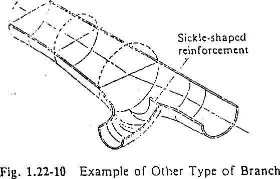
Other types of branch
Other than a wye type branch and A spherical branch,'various types of branches are known, and the branch illustrated in Fig. 1.22-10 is often used. This branch is of a type having a sickle shaped reinforcement protruded inside a pipe and a ring-type reinforcing girder omitted, and is so designed as to decrease the bending moment in U-type girder and reduce cross section of a girder.
In this branch, the sickle-shaped reinforcement is made of a thick steel plate or steel forging, and it is necessary to use a so-called anti- lamellartearing material which guarantees efficiency in the plate thickness direction, as the portion connected to a pipe shell is subject to the stress in the plate thickness direction.
A wye branch or a spherical branch for a bifurcation or trifurcation has been commonly used in Japan, but a manifold type is widely used in Europe. As for structure of this manifold type, when the diameter ratio for a branch pipe to a main pipe is larger than 3/4, it is desirable to be reinforced by an external U-type girder similarly to the one for a wye branch. With a diameter ratio less than the above, it is common to be reinforced by a curved girder in a circular shape attached on an intersecting line on both pipes. Wth a diameter ratio of a branch pipe being less than about 172 a main pipe, reinforcement by a doubling plate is also employed. Refer to the example of JIS B8243 for computation.
Hydraulics of branch
The following points are required for hydraulic characteristics of z branch:
Head loss due to branch is small. .. . /
The total head loss including those of bend pipes, reducers, reduc
ing bend pipes, etc., before and after required for branch should be small. A big turbulent flow and the secondary'flow are not generated. . . ...
For equibranch, the head loss for each pipe is equal or the difference between each pipe is small.
Even if the flow rate in one branch pipe changes, a large vortex
or a hydraulic pulsation does not take place in the flow of the other branch pipes. - .
The above items should be satisfied while water is being pumped up. .
In
order to satisfy these requirements:
In
case of equibranch, the shape is symmetrical about the main pipe
axis.
In
principle, the angle between the main pipe axis and each branch
pipe axis is small.
A
sharp change in the cross sectional area of a passage is kept to a
minimum.
Nothing
to hinder the flow is installed in a passage.
(4)
(2)
(1)

Taking the head loss coefficient due to branch as a, AH can be expressed by the following equation based on a mean velocity u0 of flow in a main pipe.
AH = a -^1
2g
Values of a are influenced by a branch angle, change in the sectional area, and so on, and in addition, Reynold’s number, and the distribution ratio of the flow, to each branch pipe influence the values of ' a. In particular; head loss coefficient varies to a large extent due to the distribution ratio of the flow.
Reynold’s number can be expressed by the following equation as to a cylinder:
vd
V
where u: Mean velocity of flow in a pipe (m/s)
d’. Diameter of pipe (m)