

I: Interval of stiffeners (cm)
IT Do'
a= 2/
say a2< 1 approximately
p* = 2.4£
=
0, but simi- dn
larly to the above, an integer closest to the value obtained from the following formula can be taken:
n
= 1.63
R.V. Southwell’s formula
_E,/( tt4 /r«\4 «2-l pV
P* r„(n*(n2-l) ( /) 12(1 - r?) \.rj
Say n2 - 1 = n2 approximately
P‘=2-59£-7&: .
2) Stiffeners
24E,Z
Pk~ (l-p?)Do'3/
where I: Moment of inertia of combined sections of stiffeners (cm4)

pressure
Tensile stress due to internal
PD PD
a~ 2t Or 2(/o-c)
where a: Stress (kgf/cm2)
. P: Maximum hydraulic pressure at a place to determine stress (kgf/cm2)
Tensile stress is generally calculated by the above formula. When bedrocks are strong enough to share part of the internal pressure, calculation should be made by the following equation.
where X: Sharing ratio of internal pressure by bedrock
Es: Elastic modulus of steel (=2.1 x 10⁶ kgf/cnri) as: Coefficient of linear expansion of steel (= 1.2 x 10~V°C)
AT: Temperature change of steel penstock (= 0~20°C) Coefficient of plastic deformation of concrete (permissible to take as = 0)
Ec: Elastic modulus of concrete (=2.1 x 10⁵ kgf/cm2)
D^. Excavation diameter of tunnel (cm)
0/. Coefficient of plastic deformation of bedrock
Et: Elastic modulus of bedrock (kgf/cm2) mg: Poisson’s number of bedrock (= 5) is usually taken as 0.5.
Sharing ratio of internal pressure by bedrock differs greatly depending on the physical properties of bedrock, initial gaps between a penstock and concrete and so forth.
If bedrock is sound with no cracks, and its elastic modulus is fairly large, it can share the internal pressure to a great extent.
But there are a lot of unknown factors in bedrock. It is not uniform ■' and there may exist such a defective portion as a partial dislocation. It is not always sure to secure a situation close to a theoretical computation. Therefore, a condition to the effect that “the pipe shell stress due to the internal pressure should not exceed the yield point of material even if it is assumed that the bedrock does not share an internal pressure,” is provided in many cases. Examples of the above are listed in Table 1.16-2.
Table 1.16-2 Example of Pressure Shared by Bedrock
Power station |
! Kiso |
T" ■ ■ Kisenyama |
Shintoyone |
Okutataragi;Okuyoshinc |
Shiniakase |
Okujahagii ||oni,awa Tamahara No.2 . L.. 1 — |
Shimogo |
||||||||||
Power (MW) |
116 |
466 |
1,125 |
1,212 : 1,206 |
1,280 |
780 I 600 |
I 1,200 |
1,000 |
|||||||||
1 |
|
1 • |
1 |
||||||||||||||
Effective head (m) Discharge (mJ/s) |
225.9 |
220 |
203 |
383.4 ;Gen.) 376 |
! 505 |
230 |
I 404.6 ! 567.0 |
518 |
387 |
||||||||
(Gen.) 60 |
(Gen.) 248 (Pump) 220 |
(Gen.) 645 (Pump) 600 |
(Gen.) 288 |
(Gen.) 644i|(Gen.) 234 |
| (Gen.) 140 |
(Gen.) 276 (Pump) 210 |
(Gen.) 314 (Pump) 252 |
||||||||||
(Pump) 25? JlPunip) 229., |
J — ♦ |
1 ... |
■(Pump) 110 |
||||||||||||||
Number of penstock lines |
1 |
2 |
5 |
4 6 « |
|
|
4 |
4 |
|||||||||
4 |
J |
2 |
|||||||||||||||
Max. design head (m) |
306 |
350 |
364 |
630 |
840 |
380 |
620 |
815 |
827 |
620 |
|||||||
Internal diameter (m) |
4.0-3.2 |
5.9-4.5 3.4 |
|
6.3-4.9 3.45-2.5 |
53-4.3 2.7-I.8 |
8.0-5.65 3.3 |
|
. 6.0-4.9 3.5-2.I • |
5.5—4.2 2.9-2.1 |
5.7-4.4 2.9-2.3 |
|||||||
Length (m) |
249.3 |
342.1 |
313.6 |
641.3 |
786.7 |
336.4 |
850.8 |
921.3 |
916.6 |
719.3 |
|||||||
Length of pressure shared by bedrock (m) |
78 |
46 |
110 |
Nearly whole! 457 length |
2+4.4 J |
278 |
1 220.9 |
200 |
667 |
||||||||
Design sharing ratio of internal pressure («?.) |
40 |
26.3 |
40 |
35-48 |
r ■ ■ ■ 22-31 |
58-6? |
24-47 |
14-22 |
22-41 |
20-45 |
|||||||
Aciuai sharing ratio of internal pressure (%) |
69-75 |
. 62-68 |
81-89 |
57-88 |
50-70 |
—■ |
■ —■• |
— |
— |
— |
|||||||
Design clastic modulus of bedrock (kgf/nr) |
30,000 |
20,000 |
75,000 |
30,000- 50,000 |
30,000-- 40,000 |
60,000 |
14,000- 60,000 |
25,000 |
30,000- 50,000 |
30,000- 60,000 |
|||||||
Pipe shell material |
HW45 |
SM50B SM58Q |
SM58Q |
SM50B SM58Q i |
SM50B SM58Q HT80 |
SM50B SM58Q |
SM50B SM58Q HT80 |
SM4IB SM58Q HT80 |
SM50B SM58Q HT80 |
SM58Q |
|||||||
Year of completion |
1968 |
1970 |
1972 |
1975 |
1980 |
1981 |
1981 |
Under construction |
Under construction |
Under construction |
|||||||
Local bending stress due to the restraint of the pipe shell displacement by means of stiffeners.
![]()
where A;. Ring’s sectional area = l,hr + r(1.56V7^r + tr) (cm2)
Fig. 1.16-4 Stiffener’s Section
Temperature stress
where at2: Stress due to temperature change (kgf/cm2) a: Coefficient of linear expansion (1.2 x 10_5/°C) E: Elastic modulus of steel 2.1 x 10⁶ (kgf/cm2)
AT: Temperature change (°C)
Stress due to Poisson’s effect
Because of restraint of longitudinal displacement of a pipe, longitudinal stress corresponding to the circumferential stress is generated by Poisson’s effect.
where an: Stress due to Poisson’s effect (kgf/cm2) v: Poisson’s ratio of steel (= 0.3) or: Circumferential stress (kgf/cm2)
PD n ar= (1 -X)
2t
Stress due to external pressure and critical buckling pressure
(1) Without stiffeners
E. Amstutz’s formula is generally used. In addition, E.W. Vaughan’s formula and Montel’s formula are also used. Vaughan’s formula is the one to have modified Amstutz’s analysis, and Montel’s formula is an empirical equationby assuming that the buckling is largely affected by an error of “out of roundness”.
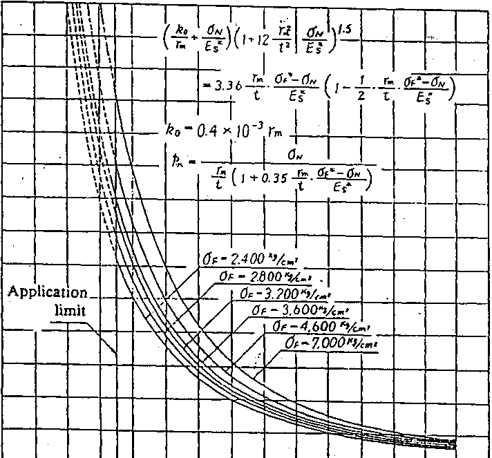
E. Amstutz’s formula (this formula conforms to an actual case within the range of Zel>35)
f k0 . aN \ | t rm2 oh Vs
t2 ’&1/ -
. - ^rm ctf -on . 1 rm <jF*-aN\
t Es* \ 2 t E* ]
where k$. Gap between concrete and external surface of pipe (cm). kQ is usually taken as 0.4 x 10"3rm.
(cwlT+U^V.-
where aa: Allowable stress of material (kgf/cm2)
■q: Joint efficiency
uN: Circumferential direct stress at deformed pipe shell portion (kgf/cm2)
On
Pk =
—11+0.35— °F
f \ t Dr
:
%C>1
140
120
100
QO
60
40
20
140
O0
a a o
0 20 40 60 50 100 120
Ratio
of embedded pipe’s radius to shell thickness (rm/t)
Fig.
1.16-5 Critical Buckling Pressures of Embedded Pipes without
Stiffeners (by E. Amstutz’s formula).


E;W. Vaughan’s Formula
0F Oct , I /Cq Oct \ l"m
i
I'm
Op Qcr
1
t 24oc,
=U
Montel’s formula
where u: Relative error of a radius measured with the range of a. 5jO° center angle (cm)
. ;, t J: Gap between concrete and external surface of pipe (cm) (2) With, stiffeners
A. Pipe shell proper
S. Timostjepko’s formula is generally used.
S. Timoshenko’s formula
. 2nz-\-vs\
1+-TT
7r2/o
' 'I ■ ]
x«i~(i+n—
■ i. fr*
1.56*Jrmz
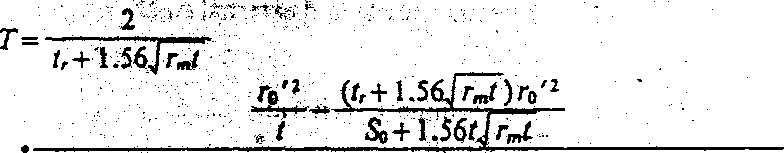
3 Irt)' \u sinh ffl+sin 0/ 2roz2
[3(lrr.?)l’’!\ > I cosh 0/-COS 0/ + So+1.56/Jr„r 3=—
Sar»tr(t±h^ , . i -
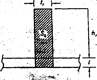
Fig. 1.16-6 . Cross Section of Stiffener
where Modified interval of stiffeners (cm)