

Trash Rack
Article 71. Trash Rack
A trash rack shall be provided at the headrace entrance when such drift- 'ing debris as wood, ice, water plants or trash flow in and damage turbines, pumps, gates and valves.
The trash rack shall be of a shape which has a small loss of head and the shape, dimensions and support conditions shall be decided by taking into account the velocity of the flow so that the running water does not produce -vibrations.
The trash rack and its support structure shall be so structured as to withstand the required differential head, which is decided by taking the possible trash volume into consideration.
Description:
The trash rack can be classified into such types as movable and fixed,- vertical and inclined, and the spacing of the trash rack bars is determined by the size of the debris.
Generally trash rack bars are installed parallel to the stream lines and are spaced approximately 60mm to 150mm apart. The width of the bar is generally less than 12 times its thickness but approximately a minimum of 50mm. In order to prevent the trash rack bars from buckling horizontally, the supporting space is. generally taken as less than 70 times the thickness. The allowable stress when horizontal buckling is considered can be determined from, the following formula:
Allowable Stress = 0.6 x Yield Stresss x (1.23 -0.0153L/Z)
where L: Horizontal supporting space (cm)
t: Thickness of the bar (cm)
The flow velocity passing through the trash rack is generally 0.6m/s to Irh/s but the mean velocity through the trash rack of a , tailrace or an intake at a pumped storage power station sometimes reaches 3 to 4m/s.
Loss of head by the trash rack bars is determined by the following formula (Kirschmer’s formula):
, . . t .4/3 u2 .
hr — k (—) —~ sin a b' 2g
where hr: Loss of head when passing through the trash rack (cm) t: Thickness of the trash rack bars (cm) b: Space between bars (cm) u: Approach velocity (cm/s) g: Gravity acceleration (cm/s2)
a: Angle of trash rack from the horizontal plane
k: Factors in Fig. 2.71-1
Generally the differential head for design is 0.6m to 1.5m for a low head. However, 65% to 100% of the trash rack height has sometimes been em-, ployed as a design head when there is a great deal of debris and insufficient cleaning. L .
’Suitably spaced horizontal girders should be installed downstream of the trash rack bars and the hydraulic pressure from the trash rack bars should be transmitted to the side walls through the horizontal girders. The girders should also be able to withstand these differential heads. Deflection of the horizontal girder should be less than 1/600 of the span. The trash rack bars should be straight and the connecting members should not touch the rake.
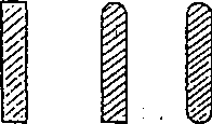
A force of flow direction works on a trash rack water but when the flow velocity becomes high, Karman’s vortex develops downstream of the trash rack bars, and a force square to the flow direction of certain frequencies works on the trash rack bars. The force and frequencies increase in proportion to the velocity of the flow. Therefore, when the velocity of the flow passing through the trash rack is high, careful study should be made of the vibrations caused by the force square to the flow direction.
The frequency by this force square to the flow direction is determined from the following formula:
![]()
where f: Frequency of force square to flow direction by Karman’s vortex (Hz)
U: Flow velocity (cm/s)
d: Thickness of trash rack bars (cm)
St: Strouhal number (factors shown in Fig. 2.71-2)
*
o E
0.255
0.130
0.155 0.200 0.235 i 0.265
0.125
0.150 0.175 0.200 0.225 0.250 0.275 S.


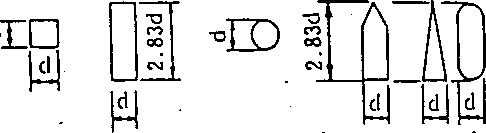
Fig. 2.71-2 Shapes of Trash Rack Bars and Strouhal Numbers
A range of f/fn (where f is the frequency of a force square to the flow by Karman’s vortex, and fn is an inherent frequency of the trash rack bars) of 0.65 ~ 1.18 is considered to be a resonance area. In order to avoid this resonance area, the inherent frequency of f„ of the trash rack bars should be increased so that fn/f 1.67 (j/f„ 0.6). However, we
recommend the adoption of fn/f 2s 2.5 (J7fn 0.4) for design by taking account of the accuracy of the Strouhal number and the other numerical figures.
&"
Section 4 Manufacture
Article 72. Processing of the Skin Plate
Skin plates to .be bent shall be uniformly and carefully bent by a bending roller or other machine.
Description: *
Refer to Description, Article 30., Chapter 1 and in the Description read “skin plate” for “shell plate”.
Article 73. Assembly
The gate leaf, gate guide, gate hoist, etc., shall be precisely assembled so that the dimensions and shapes of each part suit the design and. so that their functions can be sufficiently provided.
When a gate guide and gate leaf cannot be completed in the shop, a trial assembly shall be made in the shop to ensure that their shapes and dimensions conform to the design.
Description:
In assembling a hydraulic gate, if each part cannot be assembled as speci-
• fied in the design dimensions, the operation and the water-tightness after completion are likely to be insufficient. When a relatively small hydraulic gate assembled in the shop can be transported to the site, the dimension measurement should be made carefully in the shop, and then these measurements should be confirmed against the design dimensions (drawing dimensions). Finally the gate should be transported to the site after it is ^properly reinforced.
A trial assembly of a large sized gate guide and gate leaf should generally be made in the shop and any deformation should be corrected so that the assembly conforms to the design dimensions (drawing dimensions). Then, a dimension measurement list should be prepared and match marks should be applied. Disassembly and packing should be undertaken and the gate shoul’d be sent but. If the gate guide has already been installed, the dimension measurement list for its installation should be checked with the gate leaf and any required adjustments should be made.
Wheel pins and pin supports should be arranged in advance so as to be adjustable with an eccentric pin system or liner.
Especially in a welded structure, strain is likely to occur and thus extreme care should be taken concerning the contraction of a long span gate and the strain of the Hat plane of a gate guide, by welding.
Section 5 Installation
Article 74. Handling during Transportation
A hydraulic gate shall be carefully handled so that it does not become deformed or damaged during transportation for the manufacturing process and installation.
Description:
A hydraulic gate is generally installed at a place where the transportation conditions are poor,and the gate is likely to be deformed or damaged during the transportation due to the long distance driving on rough roads. It is preferred that members be transported as a large block as often as possible and that the part of the block that lacks rigidity be properly reinforced. The machine-finished faces should be protected with wood or some other item and proper paint or grease should be applied so that they do not become rusty during transportation.
Special attention should be paid to the case where no crane'is available for the loading and unloading operations. Electric and mechanical parts should be particularly carefully handled and, if possible, should not be exposed to rain.
Rubber seals are generally transported in a wound condition which leads to deformation and therefore they should be unwound and kept open before installation.
Article 75. General Installation
A hydraulic gate shall be accurately installed so that its shape and dimensions can exert their functions properly.
Description:
The hoisting operations and water-tightness of the hydraulic gate are greatly influenced by the installation work and therefore the gate should be installed so as to function properly by referring to the trial assembly in the shop dimensions. The water-tight parts should particularly be carefully installed.
The initial strain is an important element in the buckling of the gate arms of the radial gate in which the members are subject to very large compression and bending moment. Thus the gate should be carefully installed so that the initial strain is within 1/1000 of the gate arm length.
Article 76. Consideration of Floods during Installation
When installing a hydraulic gate during a flood season, the work shall be done under conditions which avoid any damages due to flooding.
Description: ' ' : ''f. .1.... ' .a? a '
It is generally desirable to avoid installation of a hydraulic gate during flood season. However, when it is impossible to do so, anti-flood measures should be established in advance bearing in mind that the hydraulic gate under construction might be flooded, and that extreme damage might be generated due to the damages or the washing away of the member materials or obstruction of the flow by the gate itself.
Thus, such countermeasures should be taken as the assembling of the gate hoist first, and quickly hoisting up the gate leaf under assembly as soon as a flood warning is issued, or the assembling of the gate at a high place so that the flood water can run down under it.
It is also preferrable to assemble the gate during the dry season and to avoid the rainy season.
Article 77. Installation of the Gate Guide and Anchorage
The gate guide and anchorage shall be accurately installed so that the gate leaf operates smoothly.
Description:
In order to smoothly operate the gate leaf, the accurate installation of the gate guide and anchorage which are subject to hydraulic pressure con- . > centation of the leaf is of prime importance.
<■ For a fixed wheel gate, the roller seating face for each roller should be flush and the roller track should also be flush on the left and right, and each roller should contact the roller track uniformly. If the contact is uneven, the load will be concentrated on specific rollers, thus leading to the breaking of the rollers and to irregular operation.
In order to secure good water-tightness and smooth hoisting operation for a radial gate, the left and right trunnion pin centers should be exactly aligned and the leaf sides rotating about this pin should slide precisely on the side guide.
In order to secure an accurate installation it is desirable to use proper jigs. Liners. Wedges and adjusting bolts are also often used for adjusting.
The installation work of the guide is the most important and good watertightness and smooth hoisting operation cannot be expected unless the guide is installed exactly.
In installing the gate guide, at the stage of the placement of the first stage concrete, a blockout should be made and installation adjusting bolts or reinforcing steel bars should be embedded so as to fix the gate guide at the required position precisely and rigidly. The gate guide should not be displaced by the second stage concrete. With the gate guide installed, it is desirable to prepare a measurement list for these installation dimensions for reference during the gate assembly.
For a raising type gate it is preferrable that the guide be installed so that the upper portion is somewhat wider than the lower portion.
Article 78. Installation of the Seal Part
Seal parts shall be adjusted and installed so as to minimize leaks as much as possible.
Description:
The purpose of a hydraulic gate is to stop water and so a complete shutting off is preferrable but it is generally difficult to do so. However, it is necessary to minimize the leak as much as possible.
A leak generally occurs at the corners of a hydraulic gate, and at the top and bottom gate joints of a multi-stage hydraulic gate. An allowable limit of leakage cannot be defined, i.e. the limit may vary with the type of gate, and, for example, a leak to some extent to selective (surface) water withdrawal equipment should be permitted.
A leak from the seal part is due to the irregularity of the seal contact face or to a gap between the guide members and the concrete. A leak due to incomplete contact of the rubber seals should be stopped by adjusting the protrusive level of the rubber with rubber tightening bolts or by inserting a steel liner plate to it.
It should be noted that the rubber seal may be damaged by the milk cement adhering to the gate guide or the remainders of the cut-off reinforcing steel bars, etc.
The rubber seals should be well-adjusted when assembled in the field so as to contact the gate guide under appropriate compression.
Article 79. Coating Specifications
Coating specifications shall be best suited to the atmosphere in which the gate is installed.
Description:
Coating is required for the hydraulic gate with a view to anti-corrosion and good appearance. The paint film is the most important element in exerting the effect of the coating and thus for the purposes of obtaining good film properties it is absolutely necessary to select paint suitable for - - the atmosphere, i.e. coating specifications and to conduct careful coating work.
With the progress in high molecular chemistry, various paints are available and these are classified as follows in terms of atmosphere and type with a view to stable techniques and workability.
Type and description of atmosphere
Sea Water: Atmosphere where structures are always being corroded by sea water or are exposed to sea water spray, thus placing them under the strong influence of the sea and polluted rivers running through cities.
Fresh Water: Atmosphere where structures are always submerged in a river and thus are placed under the influence of the water. Generally clean rivers, most of which run through mountainous areas. pH 6.5 to 7.5
Coast: Area within 2 km from the sea or coastline and influenced ’ mostly by salt particles.
Industrial Area: Industrial areas and built-up areas of cities in- • fluenced greatly by sulfur dioxide.
Others: Mountainous and farming areas other than coastal and industrial areas under severe conditions.
Coating system
f‘ The coating system is listed in Table 2.79-1.
Table 2.79-1 Coating System
Coating system & syrpbol |
Coating location |
Process |
Paint |
Standard film thickness GO |
Coating interval (20° C) |
Minimum & maximum |
|||||
A Epoxy resin paint system |
Sled mill/shop |
1st primer |
Zinc-rich primer (organic) |
20 |
72H-6M |
Shop |
1st layer (under coat) |
Epoxy resin paint |
60 |
||
2nd layer (under coat) |
Epoxy resin MIO painl (Note 4) |
60 |
24H-7D |
||
24H-18M |
|||||
Field |
3rd layer (intermediate coal) |
Epoxy resin paint |
30 |
||
24H-7D |
|||||
4th layer (lop coat) |
Epoxy resin paint |
30 |
Coating system & symbol |
Coating location |
Process; |
Paint |
Standard film thickness GO |
Coating interval (20°C) |
Minimum & maximum |
|||||
B Epoxy resin paijpystem (thick film) |
Steel mill/shop • |
1st primer |
Zinc-rich primer (organic) |
20 |
72H-6M |
Shop |
1st layer (under coat) |
Epoxy resin paint (thick Film) |
100 |
||
24H-7D |
|||||
2nd layer (intermediate coat |
Epoxy resin MIO paint (Note 4) |
60 |
|||
24H-18M |
|||||
Field |
3rd layer (lop coat) |
Epoxy resin paint (thick film) |
100 |
||
C Tar epoxy resin type |
Steel mill/shop |
1st primer |
Zinc-rich primer (organic) |
20 |
72H-6M J |
Shop |
1st layer (under coat) |
Tar epoxy resin paint, Class 1 |
80 |
||
24H-7D |
|||||
2nd layer (intermediate coat) |
Tar epoxy resin paint, Class 1 |
80 |
|||
24H-7D |
|||||
3rd layer (top coat) |
Tar epoxy resin paint, Class 1 |
80 |
|||
D Tar epoxy resin paint system (thick film) |
Steel mill/shop |
1st primer |
Zinc-rich primer (organic) |
20 |
72H-6M |
Shop |
1st layer (under coat) |
Tar epoxy resin paint (thick film) |
150 |
||
24H-7D |
|||||
2nd layer (top coat) |
Tar epoxy resin paint (thick film) |
150 |
|||
E Zinc chlorinated rubber paint |
Steel mill/shop |
1st primer |
Zinc-rich primer (organic) |
20 |
12H-6M |
Shop |
1st layer (under coat) |
Zinc-rich primer (organic) |
20 |
||
48H-6M |
|||||
2nd layer (under coat) |
Chlorinated rubber paint |
40 |
|||
- 16H-12M |
|||||
3rd layer (under coat) |
Chlorinated rubber paint |
40 |
|||
■ 16H-12M |
|||||
Field |
4th layer (intermediate coat) |
Chlorinated rubber paint |
30 |
||
16H-12M |
|||||
5 th layer (top coal) |
Chlorinated rubber paint |
30 |
Coating system . symbol |
Coating location |
Process |
Paint |
Standard film thickness GO |
Coating interval (20°C) |
’Minimum & maximum |
|||||
F Phthalic resin paint system |
Steel mill/shop |
1st primer |
Wash primer |
15 |
4H-3M |
Shop |
1st layer (under coat) |
Red-lead or lead-type anticorrosive paint, Class 1 |
35 |
||
24H-3M |
|||||
2nd layer (under coat) |
Red-lead or lead-type anticorrosive paint, Class 2 |
35 |
|||
24H-6M |
|||||
Field i |
3rd layer (intermediate coat) |
Ready mixed paint for upper coat, Class 2 |
25 |
||
I5H-IM |
|||||
4lh layer (top coat) |
Ready mixed paint for upper coat, Class 2 |
25 |
|||
G lead-type anticorrosive phenolic MIO chlorinated rubber paint system t |
Steel mill/shop |
1st primer |
Wash primer |
15 |
4H-3M |
Shop |
1st layer (under coat) |
Red-lead or lead-type anticorrosive paint, Class 1 |
35 |
||
24H-3M |
|||||
2nd layer (under coat) |
Red-lead or lead-type anticorrosive paint, Class 2 |
35 |
|||
24H-3M |
|||||
3rd layer (intermediate coat) |
Phenolic resin-type MIO paint |
50 |
|||
48H-18M |
|||||
Field |
4th layer (intermediate coal) |
Chlorinated rubber paint |
30 |
||
I6H-12M |
|||||
5th layer (top coat) |
Chlorinated rubber paint |
30 |
Notes: I. Surface preparation should be in accordance with SSPC-SP 6-63 Commercial Blast Cleaning or the Swedish SIS-Sa2 by using shot, grit, sand blasting, etc.
In the Table, H = Hour, D = Day, M = Month
Standard film thickness should be a mean value of each measurement but the minimum measurement should be more than 70% of the standard film thickness.
Maximum coating interval for coating system (A) or (B) is 18 months but when the construction work is short or all the coatings including a finish coating are conducted in the shop due to circumstances which cannot be controlled, it is permissible to’use epoxy resin paint (under coat) instead of epoxy resin type MIO paint. (In this case, however, the coating interval should be from 24 hours to 7 days at 20° C.)
In coating systems (C) or (D), when coating at less than 15°C during the winter, an equivalent tar urethane resin paint can be used. (In this case, however, the coating interval should be from 24 hours to 7 days at 15°C.)
In coating system (G), phenolic resin MIO paint must be applied to the third layer.
When applying coating system (F) or (G) to the gate hoist, castings or forgings, the wash primer can be omitted.
The coating system stated herein is classified in terms of the color additives of each paint as epoxy resin type, chlorinated rubber type, phthalic resin type and so on, and is further classified in detail into a combination of paints for primer, under, intermediate and top coats, painting layers to be applied and painting locations.
For film thickness, standard values as well as minimum values are specified because of the variances of surface roughness, and conditions of the welded parts and the corners of the steel materials. The welded part apt to produce pin holes should be particularly carefully coated. It is generally difficult to apply blast cleaning to the equipment of a gate hoist, but the grade of this equipment should be the same as that of commercial blast cleaning by using motor tools, disk sanders, etc.
Reference:
Ready mixed paint, Class 2
JIS
K5516
Red-lead
anticorrosive paint,
Classes
1 and 2
JI'S
K5622
Lead
suboxide anticorrosive paint,
Classes
1 and 2
JIS
K5623
Basic
lead chromate anticorrosive
paint,
Classes 1 and 2
JIS
K5624
Lead
cyanamide anticorrosive paint,
Classes
1 and 2
JIS
K5625
Tar
epoxy resin paint, Class 1
JIS
K5664
4.
Coating system to be applied.
Coating
systems to be applied are listed in Table 2.79-2 and depend on the
atmosphere. If two or more coating systems are available for the
same atmosphere, a decision should be made by taking into account
performances, workability, using conditions, etc.
For
special conditions other than those stated in the atmosphere
conditions, Description 1, a careful study should be made
separately to decide the suitable coating system.

Atmosphere Classification |
In water |
Over water |
|||
Sea Water and Fresh Water |
Coast and Industrial Areas |
Others |
|||
Guide and Anchorage |
A, B, C, D |
E? G |
E, G |
||
Leaf |
Mostly in water |
A, B, C, D |
|
— |
|
Always wet with dew |
A, B, C, D |
A. B, C, D |
A, B, C, D |
||
Mostly in atmosphere |
|
E, G |
E, F, G |
||
Auxiliary facilities |
A, B, C, D |
E, G |
E, G |
||
Gate hoist |
Outdoors |
— |
F, G |
F, G |
|
Indoors |
1 i |
— |
F |
F |
|
Hoisting framework, etc. 1 |
— |
E, F, G |
F, G |
||
A, B, C ... in the Tabic show coating system symbols in Table 2.79-1.,
Article 80. Coating Work
Surface preparation shall not be made outdoors on a rainy day or under other such adverse weather conditions. Even during indoor work, coating cannot be conducted after blast cleaning when the temperature is below 5°C or the humidity is above 85%, and thus heating or forced drying shall be required.
’ 2. Wash primer shall not be applied when the humidity is more than 90%, and other paints shall not be applied when, in addition to the above humidity, the ambient temperature is below 5°C and the temperature on the surfaces to be coated is more than 50°C.
3. Necessary and sufficient time shall be taken for the over coating interval by taking into account drying time, ambient temperatures, etc.
Description:
Refer to Description, Article 38., Chapter 1.
Surface preparation for the steel materials is to remove mill scales, rust and other foulings by blowing such abrasive materials as sand, slag, grit or shot onto the steel materials using compressed air by means of.a blast cleaning device in the steel mills or the shop. As a pretreatment, grease or machine oil on the surfaces of the steel should be removed by using an organic solvent such as thinner, etc.
Judgment of the surface preparation for the materials to be painted depends on one’s subjective point of view, thus it is different and hard to define, but in SSPC and SIS the grade standard photographs for surface
preparation are shown, thus it is desirable to judge the surface condition while comparing it to these photographs. The surface preparation has been specified as the commercial blast cleaning of SSPC which has been widely conducted in steel mills. Those blasted before they are assembled should be painted as required after removing the rust on the heat-affected weld parts and the damaged parts by using a sander or power brush after they are assembled.
Aside from the blast cleaning, the acid pickling method is also available for surface preparation by using such acid solutions as hydrochloric acid, sulfuric acid, phospheric acid, etc. but rust on the surface should be removed as thoroughly as by commercial blast cleaning.
Weather conditions and temperatures before coating are of prime importance. If a wash primer is applied at a humidity of more than 90%, a brushing phenomenon (chalking phenomenon) is generated which causes the layers to separate. As the temperature goes lower, the paint viscosity increases, thus reducing the workability and the paint drying takes a longer time.
Drying time for epoxy resin and tar epoxy resin types in particular become longer when the temperature goes below 10°C, but it has been limited in this standard to 5°C as it has become applicable by using some special additives (Refer to Article 38., Chapter 1.)
For tar urethane resin paint, the coating interval can be 24 hours to 7 days even if the temperature goes below 10°C. When the temperature on the surfaces to be painted goes above 35°C in the summer, care should be taken so that the paint does not dry too soon.
The coating intervals stated in Article 79. are based on a temperature of 20°C and a humidity of 75%, but it should be noted that the intervals are different case by case under different conditions.
Particularly for tar epoxy resin type and epoxy resin type, the maximum coating interval is within 7 days, and thus structures which require a long period before installation should basically be coated in the shop, but if this is not possible, it is Required that necessary measures such as roughening the surface to be painted be taken.
For a hydraulic gate that is always submerged, the combination use of coating and electric protection is effective. Even in this case, painting is the main anticorrosive measure and electric protection is supplemental. A suitable paint should be carefully selected.
There is the galvanic anode method and impressed current method but the former is widely employed because of its simple work process.
Article 81. Metal Spraying
In setting a metal spraying specification as an anticorrosive method substituting for coating, the specification shall be that best’suited to the atmosphere where the hydraulic gate is installed.
Description:
Metal spraying is a method to change a liquid metal into the form of .a spray using compressed air and to blow it onto the surface of a structure, thus forming a metal coating layer. The most important point for the spraying is the adhesion to the surface and thus the success of the spraying depends on the surface conditions. The reliance on adhesion equals the reliance on the metal spraying. This is why surface preparation for blasting is required.
For metal spraying, zinc spraying and aluminum spraying are available and metal spraying and painting can be used together.
should
be applied:
Zinc
spraying JIS H83OO
Zinc
spraying work standard JIS H9300
’ Test
for zinc spraying product JIS H8661
Aluminum
spraying JIS H8301
Aluminum
spraying work standard JIS H9301
Test
for aluminum spraying product JIS H8663
It is required that thorough consideration concerning the estimate of durable years be given to a hydraulic gate to be used in sea water because: of-the effects of different metals.
When blasting or spraying a hydraulic gate, etc., trouble may occur if there are dead angles, poor ventilation or sharp, edges, thus they require a careful advance check.
For paints for combined application of metal spraying and coating, a careful study should be made of the atmosphere and purpose of use of the items to be painted and then the specification and work process should be decided.
Article 82. Builder’s Name Plate
A builder’s name plate shall be attached to the hydraulic gate stating the builder’s name, month and year of manufacture, width, height, weight of the gate leaf, and operating speed. The name plate may be omitted for a small size gate.
Description:
A builder’s name plate stating the required matters should be attached to the proper place of a gate leaf, gate hoist, operating bridge, etc. of a hydraulic gate for the purpose of coping with future accidents, and repairs and modifications.
Since the plate marks the main particulars of the hydraulic gate concerned for as long as the gate exists, less corrosive materials should be used.
Article 83. Running Test
Soon after the completion of installation a running test shall be run to check the gate leaf, gate, hoist, emergency lowering device, and auxiliary power equipment for normality and to ensure safety.
Description:
After the completion of the installation, it is general to conduct a suffi-. cient running-in test and a test for confirming operations under no load conditions, and then to conduct each test under load. It may take a long time to fill the dam with water and a test under hydraulic pressure may not be possible depending on the downstream conditions, but it is desirable to conduct a trial running test with water fully filled soon after the , completion.
The gate leaf should be checked under full water level conditions for touch of the rollers and for leakage, and then a gate operating test should be run. During these tests, electric currents and voltages of motors at each opening position of the gate and the leafs operating speed should be measured, and the leaf should be inspected for leaf vibrations, gap between each roller and the gate guide, conditions of the brake or self-lock of the gate hoist, conditions of the limit switch, gate leaf position indicator, bearings and gears.
An operating test should be run for a hydraulic gate having an emergency lowering device, auxiliary power equipment, and remote control device to check if they are exactly as designed.
In order to carry out these tests, it is preferrable to prepare the test running procedure in advance and to conduct the tests based on it.
Section 6 Inspection
Article 84. Inspection .
In the process of manufacturing a hydraulic gate, the following inspections shall be made, but some of them can be omitted depending on the type and importance of the gate:
Material inspection
Lofted drawing inspection
Welding inspection
Shop trial assembly inspection
Field inspection
Description:
When manufacturing and installing a hydrualic gate, the above inspections should be made as appropriate in order to ensure that the materials are used as planned, that the dimensions are the same as those.specified in the drawings and that the performances can be obtained as planned. In the material test, whether or not the specified materials are used should be checked and in the shop trial assembly inspection various important dimensions should be measured and the load test of the gate hoist should be conducted if required.
The field inspection is conducted to ensure that those items manufactured and installed can exert the required capabilities and can be usable, by checking the dimensions of each part and the water-tightness, as well as by conducting the operation test.
The welding inspection is given in detail in Chapter 4.
Section 7 Maintenance
Article 85. Maintenance, Inspection and Control
Maintenance, inspection and control for a hydraulic gate shall be conducted properly to well-maintain each function.
Description:
The hydraulic gate should be inspected regularly or as appropriate in order to maintain the functions and to prevent accidents beforehand. The historical record, specifications, design drawings, test records, and operation manuals for the hydraulic gate should be maintained. In addition, the inspection record, operating record, and repair record, etc., should be well-maintained.
The interval of regular inspections should be set in the control standards established separately taking into account the use conditions, func-. tions, and importance of the gate.
After flooding, it is desirable that the gate leaf, gate guide, and auxiliary facilities should be inspected temporarily and immediately.
Article 86. Leak Prevention
In case of an excessive leak from the seals, immediate replacement or * repair shall be made.
Description:
If the leak increases because the rubber seal deteriorates or becomes damaged, it should be replaced with a new one.
Besides, a leak is likely to occur at the intersection point of an expansion joint for a dam to a bottom guide. A leak at such a location should be stopped by the injection of asphalt or other fillers.
Article 87. Freeze Prevention
A hydraulic gate requiring operation during the winter season shall be maintained so ;as not to incur trouble due to freezing.
Description:
For a hydraulic gate which may be required to operate even in the cold season the gate leaf, guide and gate hoist should be prevented from freezing, thus making the gate always operable.
Freeze prevention methods for the gate leaf and gate guide are as follows:
Thermal conduction: embedded electric healing wiring type, space
heater type '
Thermal convection: heated air circulation type
Water surface stirring: water or hot water injection type, froth type
Radiation: infrared radiation type ; ,
Leaking water from the seals tends to be frozen into an ice block which attaches to the gate leaf and gate guide thus causing trouble. Care should always be taken to prevent leakage.
When there is no leakage, however, the gate front face is heavily iced up in a very cold region and thus manual ice breaking work becomes necessary. Some measures should also be provided for preventing the gate hoist from freezing in order to avoid malfunction of the gate.
Even if there seems to be no frozen ice, when operating the gate it is first required to ensure that there is no frozen ice in the sealing parts before operation.
Article 88. Maintenance of Support
Gate supports shall always be well-maintained so as to operate smoothly.
Description:
The support for a gate leaf is a point where the hydraulic pressure working on the leaf concentrates and so all the supports should be in a completely maintained condition so that they operate smoothly under hydraulic pressure. In other words, main wheel pins of a fixed wheel gate, and trun- ' nion pins of a radial gate are always required to be covered with appropriate lubricants. In particular, the wheel pins of a fixed wheel gate are numerous and the foothold for maintenance is generally poor thus leading to insufficient maintenance.
The hinged supports of a hydraulic gate are generally subject to large pressure and revolve at a low speed, and so extreme care should be taken so that the lubricant is always applied throughout the entire surface. With insufficient lubrication, bearings are likely to be seized, and the wheel pin tends to rotate with the wheels, thus leading to trouble in operating the gate leaf.,Again, a thorough lubrication is essential for smooth operation.
Article 89. Maintenance of Gate Hoist
A gate hoist shall always be well-maintained so as to secure perfect operation of the.gate leaf.
Description:. -
A gate hoist should be in perfectly maintained condition so that the gate leaf is operable at any time. For this purpose, it is necessary to prepare ’’Hydraulic Gate Inspection Procedures” to specify how to conduct a regular inspection and an inspection before operation.
Attention should be paid during the inspection to lubrication, occurrence of rust and slackness of tightening bolts at each part of the gate hoist, to temperature increases in the bearings, to checking of the electric parts and the rope wires, and to confirming the operation of the limit switches and brakes, as well as to greasing the wireropes. Cleaning up is also required for the rubber seals and rollers to rid them of tree leaves or wood chips before operation.
Article 90. Maintenance of Auxiliary Power Equipment
Auxiliary power equipment shall always be well-maintained so as to afford rapid and secure operation.
Description:
Engines for the auxiliary power equipment should always be under good maintenance conditions so as to start at any time, and the operator is required to master how to start them. For starting measures, batteries, compressed air, manpower, etc., are available. If batteries are used, they should be kept well-charged and warm to ensure starting even in extremely cold weather. If compressed air is used, it should be kept at the required pressure.
It is also necessary for the operator to use generators by understanding their performances and mastering their handling.
Article 91. Repair and Replacement .
Repair or replacement shall be made soon after the risk of malfunction of a hydraulic gate is incurred because of a decrease in material thickness, deterioration and corrosion of materials, etc.
Description:
Repair or replacement of a hydraulic gate should be made based on the following:
When there is a fear that the stress of each member exceeds the allowable stress for each material used, thus leading to a breakdown.
-. 2. When the gate is estimated to be in danger because of structure instability due to vibrations.
When there is some trouble in operating the gate because of an excessive drop in performance.
Parts generally repaired or replaced are the rubber seals or wireropes.
Attention should be paid to deterioration of the hydraulic operating fluids, to the existence of foreign matter, and to.the volume of oil for an oil hydraulic device, if attached. If the above is a cause for an oil pressure drop Or increase, the filter should be replaced or the oil should be replenished.
A wirerope should be replaced when more than 10% of the total wires of the rope are broken or when the diameter of the wirerope decreases by more than 7% of the nominal diameter.
Article 92. Maintenance Gate
’ A stoplog or floating gate shall be provided for the purpose of repairing a hydraulic gate, etc. This shall not be applicable if the gate leaf, etc., can be repaired without the maintenance gate.
Description:
A stoplog or floating gate is generally provided upstream of a hydrau- 'lic gate in full time use and when repairing the gate the above is temporarily used as a substitute for the gate so that the repair work can be done without lowering the water level in a reservoir.
However, the above device can be omitted if the water level in the reservoir can easily be adjusted and lowered below the gate sill.
Extreme care should be taken in storing or mooring the above stoplog ; or floating gate.
Article 93. Recoating
■ Recoating shall be made immediately when the coating of a hydraulic gate deteriorates or becomes damaged.
Description:
jy^coating should be made to a hydraulic gate at certain intervals. When recoating, the paints used before should be carefully studied and checked, and the same or similar ones should be used again.
Recoating should be in accordance with Articles 79., 80. and 81. of this chapter.
Article 94. Hoist Room
A hoist room shall be provided for the hydraulic gate, as appropriate.
Description:
It is desirable to provide a hoist room for the gate hoist of a hydraulic gate installed for a dam or river which requires operation without failure even in heavy rain, typhoons, or snow.
Article 95. Access Bridge and Access Facilities
An access bridge and other appropriate access facilities shall be provided for a hydraulic gate, as appropriate.
Description:
An access bridge, stairway, etc., should be provided for a hydraulic gate to facilitate the making of the necessary inspection for maintaining each function.
. Chapter 3 STEEL STRUCTURE