

Velocity of flow
Fig. 2.64-2 Gradient Downstream of Gate Groove
is employed for a ring follower gate, etc., and the offset should be made so as not to produce a protrusion looking from upstream.
is employed for a jet flow gate, and (3) is employed for a slide gate. These are designed to prevent a rapid flow from penetrating the gate groove . by contracting the flow.
is employed for a slide gate by attaching an offset downstream. The groove width (PF) should be as small as possible and bevelling of the upstream corner should not be done. The downstream slope should be smoothly connected to the side plate. In this way, partial water discharge is possible under a high water head of about 70 to 150 meters. Refer to Fig. 2.64-2 for gradients downstream of a gate groove.
Article 65. Conduit Pipe
Conduit pipes shall be free from any trouble due to high velocity flow and shall be strong enough to withstand both internal and external pressure.
Description:
The shape of a conduit pipe should be free from trouble in discharging water and strong enough to withstand internal hydraulic pressure and such external pressures as seepage pressure when the pipe is empty, and concrete pressure and grouting pressure when the pipe is embedded.
A ring girder type and a dowel type are available to support internal and external pressures. However, the ring girder type should be employed at the inlet where a guard gate is installed and at the downstream end where a main gate is installed by taking account of the retention of the exact shape and precision of the installation.
For the intermediate part of the pipe, the type is selected depending on the situation, however, the dowel type is generally used as it is more economical than the ring girder type.
For the ring girder type, the whole load can be supported by the pipe itself but th$ dowel type cannot support the concrete pressure when the pipe is embedded and therefore it is necessary to prevent the pipe from buckling by supports or other proper means. Otherwise the dowel type should be used in combinaton with the ring girder type.
The dowel type should not be employed where the concrete is so thin that the effect of the dowel can not be anticipated.
In designing the conduit pipe, the provisions of Chapter 1 should be applied. The maximum water level for design should be considered’ for the internal pressure and the seepage pressure should generally be equal to .the design pressure upstream from the water stop collar. The seepage pressure should gradually be reduced in a straight line downstream from the water stop collar and should finally reach zero at the downstream end.
The grouting pressure is of a temporary nature in the process of construction work and thus a corrosion allowance should be included in calculations. For a rectangular shape the allowable stress of the pipe shell platp and ring girder can be increased by 50% of the values stated in Article 12., Chapter .!.
Smoothness of the passage surface is important for high velocity flow and even less than a 1mm irregularity may be a cause for cavitation. Especially for a gate with the purpose of partial discharging having more than 20 m/s flow velocity, stainless clad steel having smooth surfaces and good anti-cavitation properties are used at the passage upstream and downstream.
For a bend pipe, the bending angle of each section should be as small as possible so that the inside face can be as smooth as possible. Care should be taken to the change of the circular radius at the corner.
“Worn out horse” type deformation is also a problem for the weld structure and so consideration to the selection of plate thickness and welding method is required. If a flange joint is offset, it is preferred that this part be grind-finished and be smooth within the gradients shown in Fig. 2.64-2.
Article 66. Air Pipe
A high pressure gate and valve shall be equipped with an air pipe capable of supplying enough air downstream of each as appropriate.
Description:
Air supply devices are as follows:
Air pipe to smoothly feed and drain the water insid.e a conduit pipe.
An air pipe having 0.5 .to 1% of the conduit pipe sectional area is provided at the highest point of the conduit pipe. However, in some cases, an air pipe with a larger section is required depending upon the air pipe length, the time for water feed and drainage, and the allowable pressure drop inside the conduit pipe. (Refer to (1) and Fig. 2.66-2.)
Air pipe to keep the pressure downstream of the gate normal by sup-- plying air downstream when partially opening a gate or valve which,
.is installed halfway in the conduit. (Fully open operation is included - when downstream is designed as an open conduit.)
Volume of air required is determined from:
= 0.04 (Fr - I)085
where Qa: Volume of air required (m3/s)
Qj. Outlet discharge (mVs)
Fr: Froude number just downstream of the gate
For a conduit pipe of uniform section which covers the entire thickness of the dam, the maximum air supply volume is generated with 75 to 80% of the gate opening position. When the cross section is reduced in the downstream direction the maximum air supply is produced with 30 to 40% of the gate opening position. For a conduit pipe which covers • half of the entire thickness of the dam with a widely expanded downstream cross section, a 100% opening generates the maximum air supply..
The air volume supplied to the widely expanded conduit pipe tends to be smaller than that derived from the above formula. The air pipe section is calculated by determining the air volume required using the above formula and by taking the air velocity inside the pipe as 45 m/s, but the above formula is said to give excessive air volume and thus in recent years the air velocity inside the pipe has been taken as approximately 90 m/s in some cases.
Based on the above conditions, confirmation should be made if the pressure drop inside the conduit pipe is less than 0.15 kgf/cm2 by calculation. The opening of the air pipe should be located downstream of the gate and in a place where the opening does not contact the flow. (Refer to (2) Fig. 2.66-2) J
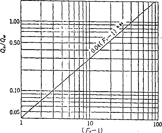
Fig. 2.66-1 Volume of Air Required

Fig. 2.66-2 Air Supply Device
. Air duct to prevent negative pressure and cavitation at a stream sepa
ration place generated around the gate or valve.
An air duct is installed for air circulation at a place where negative pressure is likely to occur, as deep as 300mm to 500mm in general, and the duct should cover the entire negative pressure area. (Refer to (3) Fig. 2.66-2)
. Air pipe to keep the pressure conditions downstream of the gate nor
mal and to smoothly operate the gate when closing under current at a guard gate (coaster gate) of the main outlet equipment and at an intake gate.
The above Paragraph 2 should be applied, but the air velocity inside the pipe is larger than that in Paragraph 2 and the pressure drop inside the pipe is often taken as being larger. It is necessary to decide the location of the opening by taking the direction of the high velocity flow -* into full consideration. _•
In addition, care should W taken so as not to cause trouble with control or to adversely affect the structure in the control room due to lack of air. (Refer (1) Fig. 2.66-2)