- •Section 1 General
- •Material and Allowable Stress
- •Pressure Lining Part
- •I: Interval of stiffeners (cm)
- •It: Moment of inertia of stiffener (cm4)
- •V: Coefficient of kinetic viscosity of flow for water at 20°c 1.0 X io-6 (m2/s)
- •Attachment Installations
- •28 Days design standard strength of concrete (kgf/cm2)
- •Chapter 2 hydraulic gate Section 1 General 1
- •Gate Leaf, Gate. Guide and Anchorage
- •13 : Temp, rising ratio 5.6°c/h (10°f/h) c : Temp, rising ratio 8.4°c/h (15°f/h)
- •Gate Hoist
- •I: Geometrical moment of inertia (cm4) I: Distance between supports of a spindle (cm)
- •Fixed Wheel Gate
- •Radial Gate
- •Long Span Gate
- •Bottom Hinge Flap Gate
- •High Pressure Gates and Valves
- •Velocity of flow
- •Selective Water Withdrawal Equipment and Surface Water Withdrawal Equipment
- •XGatc leaf
- •Trash Rack
- •Section 1 General
- •Section 3 Fabrication and Installation
- •Test piece width/test piece thickness (w/t) Standard tensile strength of hand welding joint
- •Standard tensile strength of automatic welding joint
- •Example (1) Net width of the arrangement of tightening holes as il- lustrated in Fig. 5.6-1 is as follows:
- •Section 2 Riveted Joints
- •Table 5.8-1 Combination of Materials, of Rivets and Parent Metals
- •Section 3 High Strength Bolt Joints
- •Table 5.16-1 Correction of Offset
- •Table 5.16-4 Torque Coefficient
- •. Section 4 Bolted Connections
- •Chapter 6 safety and sanitation
- •I: Geometrical moment of inertia of wheel rail (cm4)
Radial Gate
Article 46. Shape and Structure of a Radial Gate
A radial gate shall be of a shape and structure suitable for the purpose of its use, shall ensure perfect gate operation, and shall not generate vibrations even during partial discharge.
Description:
A radial gate does not need a gate groove and the hydraulic characteristics of its bottom shape are excellent during discharge. The opening' and closing operations are undertaken during rotation around a trunnion pin which makes it possible to reduce the height of the operating pier thus giving both economic and appearance advantages. These types of radial gates are frequently used for crest spillway gates and high pressure outlet discharge gates because of the above mentioned advantages.
There are many different types of frame structures such as horizontal main girders with vertical continuous girders, horizontal main girders with vertical trussed girders, vertical main girders with horizontal continuous girders, etc.
There are trussed shapes and Rahmen shapes for gate arm stiffening types, and 1-sections and H-sections are used for main girders and gate arms. In some cases, a box section is also used. Compared with a fixed wheel gate, the radial gate is a more complicated structure, members which have a larger slenderness ratio are often used, and a large load is concentrated at the trunnion. Therefore, it requires careful design and manufacturing.
Article 47. Framework
In principle, each framework shall be calculated as a Rahmen structure, connecting neutral lines of the gate arm and the main girder, by taking the trunnion pin as a fixing point.
Description:
This Article specifies the horizontal main girder type.
Gate arms and main girders constitute the Rahnien in a flat plane shape. For the shape of the framework, there are gantry types and types.
When using a bearing other than a self-arranging type at a trunnion pin bearing, computation should.be made considering it as a Rahmen with trunnions as a fixing point.
Article 48. Gate Arm and Arm Bracing
The buckling length of the gate arm on a horizontal plane shall be taken from the trunnion pin center to the neutral line of the main girder and the buckling length of a vertical plane shall be the distance between panel points of the arm bracings when trussed type stiffening is conducted.
Members for gate arms and arm bracings shall be decided by taking into account the weight, bending moment by the friction of the trunnions during operation, and the loads of the operating force in addition to the axial forces.
Description:
For buckling length within the vertical plane of the gate arms, the restraint to the displacement of each gate arm at the trussed panel point becomes extremely strong when trussed type stiffening is conducted, and thus the buckling mode seems to be close to that which takes each panel • point as a support. Therefore, the buckling distance of the gate arms within the vertical plane should be taken as the distance between trussed points.
The buckling length when Rahmen type stiffening is used becomes much larger than each panel point distance and therefore it is necessary to study the buckling length thoroughly.
Article 24. of this chapter is applicable to gate arms which should be calculated as columns under compression. The compressive stress of the bending moment should be added.
Two gate arms on one side are used in relatively many cases,.but in some cases three arms are also used for a hydraulic gate that has a large leaf height. A 1-arm gate is also manufactured but is less frequently used. The hydraulic load shared by each gate arm can easily be calculated for two arms because they are static, but consideration of the structural system as a whole is required for three or more gate arms because of an increase in the statically indeterminate degree.
The gate arm is influenced by axial force derived from hydraulic pressure and by moments from gate operating load and friction at the trunnions. Generally the gate arms are arranged closely around the trunnions and thus bracings are hard to place. Therefore, such considerations as enlarging the flanges of the gate arms or enlarging the gusset plates are required.
The dimensions of the arm bracing should be either the member dimensions calculated from Paragraph 2 of this Article or those calculated by assuming that 2% of the gate arm axial compression acts on each panel point, whichever is greater.
Article 49. Fixing Point of Arm Bracing
When making a trussed type stiffening, fixing points of the arm bracing shall be so structured as to retain the strength of a panel point. .
Description:
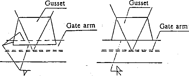
Refer to Fig. 2.49-1 for fixing a gusset. The thickness of a gusset plate should be more than that of a member connected but 8mm must be the minimum thickness.

Fig. 2.49-1 Gusset
Fig.
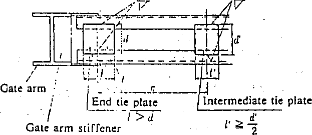
2.49-2 Tie Plate

Members used as a bracing should be as wide as the gate arm (combined members inclusive). An end plate should be arranged as close to each end of the combined member as possible and a tie plate should be used in the middle of the member. Refer to Fig. 2.49-2 for the-size and pitch of the tie plate.
'
a
To (cm)
c
< 5Or (cm)
Pitch of the tie plate
where r: Minimum radius of gyration of the area as each bracing member (cm)
An end tie plate can be placed further inward from the end if a gate arm stiffener is installed.
/•Article 50. Anchorage
Anchorage is an important point where the total hydraulic pressure from the leaf support concentrates and thus the anchorage shall be so structured as to transmit and spread this Hoad surely, widely and safely to the concrete pier. A type suitable for the purpose of its use shall be selected.
Description: • 1
There are several types of anchorages such as the concrete bond type, the bearing plate type and the pre-stressed concrete type, etc.
For a bearing plate type anchorage, an insulation material should be applied for about 1/3 of the total length downstream in order to protect the downstream concrete by avoiding the adherence of the concrete.
In any structure, the anchorage should be placed more than 200mm inside the concrete edge in consideration of safety. For bearing plate type anchorages and bond type anchorages, the shear dangerous section of the concrete should be checked.
The allowable stress for steel for pre-stressed concrete should be based on Article 12. of this chapter but it should not be increased against the load during an earthquake.
A trunnion and its anchorage should be of sufficient strength and care should be taken so as to reduce the sliding friction between the trunnion hub and pedestals because of the thrust load working on those parts due to the inclined gate arms. The anchorage should be of a trouble-free structure even when the-angle of the hydraulic pressure center changes.
