

Fixed Wheel Gate
Article 38. Shape of Fixed Wheel Gate
A fixed wheel gate, suitable for the purposes for which it is being used, should operate without failure and should be of such shape.as to give minimum vibrations during underflow discharge. It should have a minimum down-pull and uplift force.
Description:
Fixed wheel gates arc generally classified into open waterway type gates (three sides watertight) or conduit type gates (four sides watertight). Fixed wheel gates are also classified in terms of the purpose of use in the following ways: t
Flood control
'2. Flow control
Emergency closing
Maintenance and inspection, etc.
It is desirable to obtain a shape which minimizes vibrations, uplift force and down-pull force and ensures, through past testing and experience, that the gate hoisting operation will proceed without failure. Generally, the following items should be considered:
The bottom girder should be placed where it is not exposed to rapid flow during underflow discharge so that the discharge can be stabilized.
Gate vibration may be produced by the vortex flow generated downstream during underflow discharge under a certain water level of the downstream. An attempt should be made to reduce the vibration by not allowing this frequency to coincide with the inherent frequency of the gate leaf.
In order to reduce the down-pull force, the dimensions of the bottom structural portion of the leaf, which are subjected to the influence of the velocity head, should be minimized and this portion should be of such a shape as to cause little influence by the velocity head.
Article 39. Main Girder
The main girder shall be of a shape that provides the required strength and rigidity, and the structure shall be such that each girder can share the total hydraulic pressure rationally.
Each main girder should have the same sectional shape and each girder should share the hydraulic pressure equally. Thus it is desirable to arrange the girders so that the same deflection occurs. The girders cannot share the hydraulic pressure equally when the main girders are arranged on the top and bottom, and in this case it is better to use girders whose cross sections have the same deflection. However, the above is not necessarily required for a gate leaf having high.distortion rigidity.
The shapes and numbers of the main girders should be decided so that there will be no trouble with their manufacture, transport or installation and should take into account the skin plate thickness, the number and the arrangement of main rollers, and the influence during underflow discharge.
Article 40. Auxiliary Girder
Auxiliary girders shall be of a structure designed by taking into account the skin plate support reinforcement, the main girder connection reinforcement and the gate leaf rigidity.
Description:
An auxiliary girder to support the hydraulic pressure can be calculated by regarding it as a beam subjected to a tortoise-shell type distribution load (mean hydraulic pressure of the section), and by referring to Article 19. of this chapter for a clear width when the skin plate is intended to serve as a flange.
For an auxiliary girder subjected to hydraulic pressure either on its upper or lower part, sufficient girders to support these loads should be used. For the structure of the back skin plate, it is necessary to use a sufficient number of auxiliary girders to prevent the flange on the compressive side from lateral tipping due to the main girder’s bending moment.
Properly spaced vertical girders of plate or trussed structure should be installed to increase the rigidity of the gate leaf of a large size hydraulic gate. When the main girders are widely spaced and the rigidity of the gate leaf against a hanging load and a horizontal load is required, back sway bracing can be used.
Article 41. Side Girder
A side girder shall be so structured as to safely transmit hydraulic pressure to the main rollers.
A side girder should be calculated as a simple beam or continuous beam to support a main girder’s concentrated load at the supports of the main rollers and stiffeners should be fixed at the load concentration points where the main girders and the main rollers are attached so as to transmit the loads to the web plate smoothly.
In addition to the above, the side girder is subject to hydraulic pressure, guide roller reaction and suspension load when the gate is operated, and thus some of the above items which have great influence should be studied.
Article 42. Main Rollers
The size, number and fixing places of the main rollers shall be decided so that they can safely transmit hydraulic pressure, their own weight and » the wind load to a gate guide in any position of the gate.
When under load, the main rollers shall rotate smoothly and shall be ■' easy to maintain.
Description:
Two-point-support on one side is desirable for the arrangement of the main rollers. When arranging three or more rollers on one side, it is preferable to provide some adjustment measures to align the seating faces of the rollers.
A rocker beam is recommended when multiple rollers are arranged at one support of a gate subject to a large load due to restrictions in dimensions and strength.
In order to prevent partial tread due to gate deflection, in many cases curvature is provided for the roller or for the roller rail seating faces. Curvature is not needed for a gate with high rigidity or when an automatic alignment bearing is used.
The Hertz formula should be used for calculating the strength of a roller, and the stress should be less than the allowable contact stresses of Paragraph 3.
(1) For line contact (when curvature is not provided for the roller and the roller rail seating faces)
![]()
![]()
Z = O.78C
where p: Hertz’s contact stress (kgf/cm2)
P: Working lead of roller (kgf)
E: Modulus of elasticity of roller = 2.1 x 10⁶ (kgf/cm2)
Bo: Clear seating width of roller (cm)
R: Radius (cm)
C: Half the contact width (cm)
Z: Depth where maximum shearing stress occurs (cm)
(2) For point contact (when curvature is provided for the roller or the roller rail seating faces)
_ 3 P
2tt a b
a=
1.109m a
(>1 + B)E
'(a+~b)e
Z = 0b
where p: Hertz’s contact stress (kgf/cm2)
P: Working load of roller (kgf)
a: Half the contact width (major diameter) (cm)
b: Half the contact width (minor diameter) (cm)
'm: Shape factor
E: Modulus of elasticity of roller = 2.1 x IQ6 (kgf/cm2) n: Shape factor
Z: Depth where maximum shearing stress occurs (cm)
0: Factors to give the depth where maximum shearing stress occurs. Refer to Table 2.42-1
A: Factor
B: Factor
R: Radius (cm)
R': Radius of curvature of roller or roller rail seating face (cm) '
Shape factors (m) and (n) are those decided by the rollers shape. Refer to Table 2.42-2 for these factors, 9 in this Table is obtained from:
cos-1
B-A
A + B

B A 21R R'
Table 2.42-1 Factors Giving the Depth Where Maximum Shearing Stress Occurs
a/b |
1.0 |
1.5 |
2.0 |
2.5 |
3.0 |
3.5 |
4.0 |
5.0 |
6.0 |
■ d |
0.47 |
0.56 |
0.625 |
0.674 |
0.712 |
0.738 |
0.756 |
0.774 |
0.775 |
Table 2.42-2 Shape Factors
0° |
30 |
35 |
40 |
45 |
50 |
55 |
60 |
65 |
70 |
75 |
80 |
85 |
90 |
m |
2.731 |
2.397 |
2.136 |
1.926 |
1.754 |
1.611 |
1.486 |
1.378 |
1.284 |
1.202 |
1.128 |
1.061 |
1.000 |
n |
0.493 |
0.530 |
0.567 |
0.604 |
0.641 |
0.678 |
0.717 |
0.759 |
0,802 |
0.846 |
0.893 |
0.944 |
1.000 |
(3) Allowable Contact Stress
where pa: Allowable contact stress (kgf/cm2)
p: Safety factor = 1.3 (for line contact) Safety factor = 1.0 (for point contact)
Hu: Roller’s Brinell Hardness* (kgf/mm2)
* However, the hardness of a roller’s seating face is used when the hardness of the roller rail’s seating face is lower than that of the roller seating face.
Bearing should be calculated as follows:
Plain bearing
Pa = aadl>P , - ? -
where Allowable load (kgf) ’
aa: Bearing’s allowable bearing pressure (kgf/cm2)
d: Diameter of wheel pin (cm)
/: Clear width of bearing (cm)
P: Roller’s working load (kgf)
Roller bearing
p. = s >p -
where Pa: Allowable load (kgf)
f: Safety factor (1.2 -1.5)
Co: Basic static rating load (kgf) P: Rollers working load (kgf)
Refer to Description of Hinged Supports, Article 18. of this chap-
’ ter, for allowable bearing pressures of a plain bearing.
It is permissible to take the allowable bearing pressure of a plain bearing subjected to loads under static conditions as twice those in Article 18. of this chapter.
Theoretically, stress distribution in such a short span beam, as com- .... pared with its diameter as a wheel pin, is different from that in an or-
' dinary beam, however in this standard, when calculating the wheel pin, checking the bend and shear is sufficient based on the assumption that a uniform load will act on the bearing width.
It is desirable to avoid stress concentration when a cross section is abruptly changed.
Side girders to support two wheel pins forming a rocker beam are re- ' quired to work together as a mono-structure when considered from the
point of view of a thrust load.
Article 43. Guide Roller
Two or more front rollers or shoes and side rollers or shoes shall be provided on each side of the gate leaf as guide rollers so that the gate leaf can be held exactly and can be smoothly operated.
Guide rollers are required so as to smoothly operate the gate leaf along the gate guides and it is desirable to take the distance between the upper and lower rollers as being as large as possible.
Strength of the guide rollers should be studied for the wind load during operation and storage and for the inertia force during air earthquake. When the gate leaf is 1-side-suspended, it is permissible for the guide rollers to be deformed, but the leaf should not be fatally damaged.
Some guide rollers are equipped with springs. Main rollers can serve as guide rollers and side rollers can serve as front rollers.
Article 44. Gate Guide
A gate guide shall be so structured as to safely transmit the load from the leaf support, and shall have an appropriate shape suitable for the pur-" pose of its use.
/
Description:
The gate guide should be of proper shape in terms of hydraulics and strength.
Generally maintenance and inspection of a gate guide is difficult and so it is preferable that the hardness of the wheel track be higher than that of the wheel tread. However, the material should be decided by . taking anti-corrosiveness into consideration. As a result of this, if the hardness of the wheel track becomes lower than that of the wheel tread, the roller’s contact stress should be checked by using the hardness of
• the wheel track.
The following two crack generating mechanisms around the guide are considered:
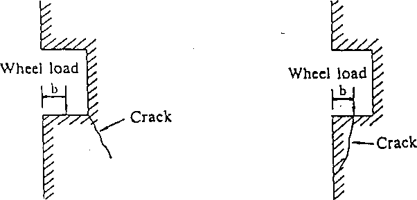
(a) Tensile crack (b) Shearing crack.
Fig. 2.44-1 Mechanism of Crack Occurrence
Tensile Crack: Cracks occur by tensile force inside the concrete
(Fig. 2.44-1(a)).
Shearing Crack: Cracks occur by shearing force inside the concrete
(Fig. 2.44-1(b)).
In order to design for these phenomena, the first stage concrete should be steel-reinforced as appropriate.
The distance between the guide of a large hydraulic gate and the pier side can generally be obtained from:
6 >20 + 0.1P
where b: Distance from pier side to wheel load center (cm) P: Load per wheel (tf)
In computation of wheel rails, the formulae of Andre, Hiitte, Timoshenko, and Skinner are available, but Andre’s formula is com- ’ • monly used, i.e.:
, AOZP3/4 J 2 b/kEm
k = 0.0588^
a
= 0.75
P
kbj

L ,.-ZJ
i—L~—zi;
| bf——1 ' ■
Fig. 2.44-2 Cross Section of a Wheel Rail
In addition, when the distance between adjacent wheels is smaller than half the stress distribution length of the concrete at the bottom of the wheel rail (a), the effect of the adjacent wheels should be considered.
It is desirable that the thickness of the rail be more than four times the depth where the maximum shearing stress occurs.
In addition to the calculation in Paragraph 3, local stress should be checked. An example is shown below:
(1) Local stress in the web plate
> When the wheel rail is welded, local stress in the web plate just below the roller can be obtained from the following formula:
P
°b b t
where ab: Local stress in the web plate (kgf/cm2)
P: Working load of the wheel (kgf)
bp: Width subject to pressure = 2C + 2 (tr + rz) (cm) tu: Thickness of the web plate (cm)
2C: Contact width of Hertz (cm)
tr: Thickness of the wheel track (cm)
tf. Thickness of the upper flange of the wheel rail (cm)

Fig. 2.44-3 Contact of Wheel and Wheel Rail
When a hydraulic gate is in full-time use, the allowable local stress of the web plate should be based on the bearing stress of Article 12., Chapter 1.
(2) Bending stress of the wheel rail bottom flange
w kb?
M,- j-
![]()
6
'where M/ Bending moment (kgf-cm/cm)
k: Stress of concrete determined from Paragraph 3 (kgf/cm2)
bp Width of wheel rail bottom flange (cm)
a: Bending stress (kgf/cm2)
t'p Thickness of wheel rail bottom flange (cm)
Article 45. Operating Load
The operating load shall be calculated in combination with the following items so as to be prepared for all imaginable operating conditions:
Weight of the gate leaf and weight of the ballast
Frictional force of wheel rotation
Rubber seal frictional force
Frictional force of sedimentary silt
Buoyancy
Uplift and down-pull force of the overflow
Uplift and down-pull force of the bottom flow
Description:
The operating load should be calculated in appropriate combination with the above items. It is desirable for the allowance of the closing force to be more than 25% of the total resistance force. When there is a lack of closing force, it is recommended that ballast be added to the gate leaf.
Frictional forces of the wheel rotation are generally calculated using the following formulae:
(1) Fixed wheel gate:
/ d\
—~p
2
where Fw: Frictional force of the wheel rotation (tf)
P: Total hydraulic pressure during gate operation (tf) /i,: Coefficient of rolling friction of the wheel (0.1) (cm) /z2: Coefficient of sliding friction of the pin (Refer to Article 18. of this chapter for roller bearing.) d: Diameter of the wheel pin (cm) D: Wheel diameter (cm)
(2) Caterpillar gate:
P (mi + p-i)P . n\P
2
where F/. Frictional force of the roller rotation (tf)
P: Total hydraulic pressure during gate operation (tf)
/x(: Coefficient of rolling friction between the first plane and the roller (cm)
H2: Coefficient of rolling friction between the second plane and the roller (cm)
/Xj = ^2 = 0.1
D: Diameter of the roller
The frictional force of the rubber seal is determined from:
F=p.r(q + Pb)Ll
where. Ff: Frictional force of the rubber seal (tf)
Coefficient of sliding friction between metal and rubber (Refer to Article 17. of this chapter) q: Initial pressing force of rubber (tf/m) P: Mean hydraulic pressure working on the rubber (tf/m2) b: Clear width of rubber subject to pressure (m) E/: Total sliding length of the rubber (m)
The frictional force by sedimentary silt (sliding frictional force between sedimentary silt and the skin plate) is determined from:
«•
where Ff: Frictional force by sedimentary silt (tf) y.t: Coefficient of sliding friction between metal and silt = 0.3 to 0.5
Pe: Total sedimentary silt pressure during gate operation (tf)
Buoyancy
Fb = 7o F
where Fb: Buoyancy (tf)
70: Water unit volume weight (tf/m3)
V\ Water volume displaced by the gate leaf (m3)
Uplift and down-pull force by overflowing water is determined from the following formula:
Fu = knoHDB
where Fu: Uplift and down-pull force by overflowing water (tf) kx: Coefficient assumed from the shape of the overflow 70: Water unit volume weight (tf/m3)
H: Water depth of overflow (m)
D: Length of overflow plate (m)
B: Width of overflow plate (m)
Uplift and down-pull force during underflow discharge is determined from:
F<i =
where Fd: Uplift and down-pull force during underflow discharge (tf) ki. Coefficient assumed from experimental values y0: Water unit volume weight (tf/m3)
Hd: Design head (m)
A: Area under pressure (m2)