

Gate Leaf, Gate. Guide and Anchorage
Article 12. Allowable Stress
The allowable stress used for a gate leaf, gate guide, anchorage and trash rack shall be as follows:
1. Hydraulic gate in full-time use
Table 2.124(a) Structural Steel < .
(unit:kgf/cm2)
Steel Stress |
5541, SM41, SMA41 |
SM50 |
SMA50 |
|||
Thickness 340mm |
>40 |
Thickness 340mm |
>40 |
Thickness 3 40mm |
>40 |
|
1. Axial tensile stress (for net ■ |
. _—_l,200 |
|
1,600 |
— |
1,800 |
|
sectional area) |
• * A ' - |
|
|
|
|
|
2. Axial compressive stress (for gross sectional area) |
7320: 1,200 |
|
-315: 1,600 r - |
|
7314: 1,800 |
_■ |
Compressive member /: buckling length of member |
20<y393: |
|
l5<y380: r - |
|
14<j376: f |
|
(cm) r. radius of gyration of area |
1,200 - 7.5(2—20) |
|
1,600-11.2(--15) |
|
1,800-13.3(2—14) |
|
for the gross section of members (cm) |
n, / 10,000,000 93<r H 6,700+(7/ |
|
1 10,000,000 80<r /, 5,000+(7) |
|
„ / 10,000,000 76^r: |2 4.500+(7) |
|
Compressive splice plate |
1,200 |
0.92 times the left stress |
1,600 |
0.94 times the left stress |
1,800 |
0.95 times the - left stress |
3. Bending stress girder’s tensile side (for net sectional area) girder’s compressive side (for gross sectional area) |
1,200 Ft |
1,600 |
1,800 |
|||
gross sectional area of wpb plate (cm2) |
—<—<30: Kb = |
|
|
|
|
|
/4r: gross sectional area of |
1 |
|
I |
|
t |
|
compressive flange (cm2 |
1,200-11(Kt-9) |
|
1,600-16(K--8) |
|
1,800-19(^7 -7) |
|
/: distance between fixed |
b |
|
b |
|
|
|
points of compressive |
„ „ Aw |
|
|
|
, - Aw |
|
flange (cm) |
But, Say — <2, |
|
But, Say y<2. |
|
But, Say — <2 |
|
b: width of compressive flange (cm) |
K=2 with |
|
K=2 with |
|
K=1 with ‘ |
|
K= 3 +An |
|
|
|
|
|
|
J 24c |
|
|
|
|
|
|
When directly fixed to the ■' skin plate etc. |
1,200 |
|
1,600 |
|
1,800 |
|
f 4. Shearing force |
700 |
|
900 |
|
1,050 |
|
Table 2.124(b) Steel Castings and Steel Forgings
(unit kgf/cm2)
_ Steel |
SC46 |
SF45 |
Stress ~~ •— |
||
1. -Axial tensile stress |
1,200 |
1,200 |
2. Axial compressive stress |
1,200 |
1,200 |
3. Bending stress |
1,200 |
1,200 |
4. Shearing stress |
700 |
700 |
5. Bearing stress |
1,700 |
1,700 |
Note: Axial compressive stress is not considered to be buckling.
High pressure hydraulic gate in full-time use
Table 2.12-2(a) Structural Steel
(unit:kgf/cm2)
Steel Stress *— |
SS41, SM41, SMA41 |
SM50 |
SMA50 |
|||
Thickness g 40mm |
>40 |
Thickness s 40mm |
>40 |
Thickness s 40mm |
>40 |
|
1. Axial tensile stress (for net |
1,050 |
|
1,400 |
|
1,550 |
|
sectional area) |
|
|
|
|
|
|
2. Axial compressive stress (for gross sectional area) |
— <20: 1,050 r - |
|
ySl5: 1,400 |
|
—<14: 1,550 r - |
|
Compressive member /: buckling length of member |
20 <-<93: r - i |
|
15<—<80: r - |
|
I4<—<76: r ~ |
|
(cm) r: radius of gyration of area |
l.050-6.1(--20) |
|
l,400 - 9.4(y-15) |
|
1,550- 10.9(y-14) |
|
for the gross seaion of members (cm) |
/ 9,000,000 < t ' / 2 |
|
OA / 9,000,000 80< f. f |
|
,, 1 9,000,000 76< r. 1 |
ia |
|
6,700 + (/) |
|
5,000+ (7)2 |
|
4,500+(7)2 |
|
Compressive splice plate |
1,050 |
0.92 times the i,r, |
1,400 |
0.94 times the |
1,550 |
0.95.* times the 1-f. |
1 Bending stress - girder's tensile side |
1,050 |
1,400 |
l;550 |
|||
(for net sectional area) |
|
ICII |
|
leu |
|
ICll |
girder’s compressive side (for gross sectional area) |
-S|: 1,050 |
stress |
— : 1,400 b~ K |
stress |
1,550 b~ K |
stress |
Aj. gross sectional area of |
|
|
8 -1 ,n. |
|
7 1 |
|
web plate (cm2) |
I? |
|
—<—<30: K b |
|
7^ |
|
A ft gross sectional area of |
* 1 |
|
I |
|
1 |
|
compressive flange (cm2) |
l,050-9(K—-9) |
|
1,400- 14(K—-8) |
|
l,550- 16(/4-7) |
|
/: distance between fixed |
b |
|
b ' |
|
v b 1 |
|
points of compressive |
|
|
|
|
A u/ |
|
flange (cm) |
But, Say —<2, |
i |
But, Say -7 <2, K = I with |
|
But, Say ^<2 |
|
b: width of compressive flange (cm) |
Af K ~ 2 with |
1 |
|
K-l with |
|
|
K= B+-— |
|
|
|
|
|
|
< 2Af |
|
|
|
|
|
|
When directly fixed to the skin plate etc. |
1,050 |
|
1,400 |
|
1,550 |
|
4. Shearing force |
600 |
|
800 |
|
900 |
|
Table 2.12-2(b) Steel Castings and Steel Forgings
(unit kgf/cm2)
— Steel Stress -— |
SC46 |
SF45 |
1. Axial tensile stress |
1,050 |
1,050 |
2. Axial compressive stress |
1,050 |
1,050 |
3. Bending stress ' |
1,050 |
1,050 |
4. Shearing stress |
600 |
600 |
5. Bearing stress |
1,500 |
1,500 |
Note: Axial compressive stress is not considered to be buckling.
Hydraulic gate not in full-time use
Table 2.12-3(a) Structural Steel
(unit:kgf/cm2)
Steel Stress |
SS41, SM41, SMA41 |
SM50 |
SMA50 |
||||
Thickness § 40mm |
>40 |
• Thickness g 40mm |
>40 |
Thickness 5 40mm |
>40 |
||
1. Axial tensile stress (for net |
1,350 |
|
1,800 |
|
2,000 |
|
|
sectional area) |
|
|
|
• |
|
|
|
2. Axial compressive stress (for gross sectional area) |
7<20: 1,350 |
|
7*15: ■ 1,800 |
|
yS14: 2,000 |
|
|
Compressive member |
1 |
|
1 |
|
|
|
|
1: buckling length of member |
20<—<93‘* r ~ |
|
!5<y^80: |
|
„ 14<—<76: r - |
|
|
(cm) r: radius of gyration of area |
1,350-8.l(y-20) |
|
1,800-I2(y-15) |
|
2,000-I4.1(y-14) |
|
|
for the gross section of |
|
|
|
|
|
|
|
members (cm) |
I 11,600,000 93<f: 6,700+(-7) |
|
5.000+C7)2 |
|
„ I 11,600,000 »<r 1, 4,500 4 (7)’ |
aa |
|
Compressive splice plate |
1,350 |
0.92 times the left stress |
1,800 |
0.94 times the left stress |
2,000 |
0.95 times the left stress |
|
3. Bending stress girder's tensile side (for net sectional area) girder’s compressive side (for gross sectional area) |
1,350 |,35O b~K |
' 1,800 1,800 b~K |
2,000 2,000 b~K |
||||
A w: gross sectional area of |
9 I |
|
* 1 |
|
1 1 „ |
|
|
web plate (cm2) |
|
|
|
|
K<b~21' |
|
|
A,:, gross sectional area of |
1 |
|
|
|
1 |
|
|
compressive flange (cm2' |
1,350-l2(/f-[--9) |
|
1,800-18(K--8) |
|
2,000 - 22(K—-7) |
|
|
/: distance between fixed |
b |
|
b |
|
b |
|
|
points of compressive |
„ r. <4W |
|
|
|
Aw |
|
|
flange (cm) |
But, Say ^"<2, |
|
But, Say ^"<2, |
|
But, Say — <2 |
|
|
b: width of compressive flange (cm) / x= 1) + ^ |
K-l with C |
|
K=2 with ' |
|
K = 2 with |
- |
|
4 L4r |
|
|
|
|
|
|
|
When directly fixed to the skin plate etc. |
1,350 |
|
1,800 |
|
2,000 |
|
|
4. Shearing force |
800 |
|
1,050 |
|
1,150 |
|
|
Steel Stress ~ “—— |
SC46 |
SF45 |
1. Axial tensile stress |
1,350 |
1,350 |
2. Axial compressive stress |
1,350 |
1,350 |
3. Bending stress |
1,350 |
1,350 |
4. Shearing stress |
800 |
800 |
5. Bearing stress |
1,900 |
1,900 |
Table
2.12-3(b) Steel Castings and Steel Forgings
(unit
kgf/cm2)
Note:
Axial compressive stress is not considered to be buckling.
The allowable stresses of materials not specified above shall be determined based on the above provisions.
When other stress in addition to axial stress exists, the combined stress shall be determined from the following formula, and the stress should be within the allowable value.
og = Va/ + a22 - oxo2 + 3-r
where op combined stress (kgf/cm2)
op axial stress (tension taken as positive) (kgf/cm2) op axial stress square to at (tension taken as positive) (kgf/cm2)
r: shearing stress (kgf/cm2)
Allowable values for combined stress
Normally 1.5 au
' During earthquake 0.9 av
where op allowable stress (kgf/cm2)
op yield stress
Steel for joint
Table 2.12-4 Steel for Joint
(unit kgf/cm2)
Steel Stress |
SS41, SM41 |
SM50 |
||
Thickness g 40mm |
>40 |
Thickness^ 40mm 1 |
>40 |
|
Rivet |
SV34 |
|
SV41 |
|
1. Shearing stress |
|
Same as |
|
Same as |
Shop rivet |
950 |
the left |
1,200 |
the left |
Field rivet |
850 |
stress |
1,050 |
stress |
2. Bearng stress |
|
0.92 times |
|
0.94 times |
Shop rivet |
1.950 |
the left |
2,550 |
the left |
Field rivet |
1,700 |
stress |
2,300 |
stress |
Bolt |
SS41, S20C |
S35C |
|
|
1. Shearing stress |
|
Same as |
|
Same as |
. Finished bolt. |
750 |
the left |
1,000 |
the left |
' Anchor bolt |
500 |
stress |
650 |
stress |
2. Bearing stress |
|
0.92 times |
... ■■■• |
0.94 limes |
Finished bolt |
1,700 |
the left |
2,300 |
the left |
Pin |
1.700 |
stress |
2,300 |
stress |
High strength bolt for friction joint
Table 2.12-5 High Strength Bolt for Friction Joint
(unit kgf/cm2) |
|
Stress |
Shearing stress |
F8T |
920 |
F10T |
1,140 |
The'allowable tensile stress of steels for pre-stressed concrete shall be the smaller of the values in the right column in Table 2.12-6, corresponding to each application stage in the left column.
'Table 2.12-6 Steel for Pre-Stressed Concrete
Application " |
Steel |
Allowable stress for uncoated stress-relieved steel wire and strand for pre-stressed concrete, and steel bar for pre-stressed concrete |
During Pre-slressing |
|
0.60 apu or 0.70 apv |
After Pre-stressed |
|
0.50 apu or 0.60 apy |
After completed |
|
0.40 apu or 0.55 apy |
where apu: Tensile strength of steel for pre-stressed concrete apv: Yield stress of steel for pre-stressed concrete
Description:
Allowable stresses used in calculation for hydraulic gates, gate guides and anchorages have been set at 1/2 yield stresses.
There are two types of hydraulic gates: one in full-time use and the other not in full-time use. The former is further divided into low pressure gates such as crest spillway gates and high pressure gates such as high hydraulic gates. Taking into account importance, safety, economy and technical difficulty of these hydraulic gates, it has been decided to consider the allowable stresses separately for the following three types: hydraulic gates and high pressure gates which are in full-time use and hydraulic gates which are not in full-time use.
In view of the occurrence of vibrations and other unexpected increases in stress, the allowable stress of a high pressure hydraulic gate has been set at 87.5% the value in paragraph one (hydraulic gate in full-time use), and its application is shown below. This concept is also applied to a valve substitute for a gate.
High pressure outlet equipment for dam
FOR 1
Chapter 1 STEEL PENSTOCKS 7
Section 1 General 7
Section 2 Design 4
Description, 19
2. Material and Allowable Stress 31
Description: 31
3. Pressure Lining Part 46
P‘=2-59£-7&: . 48
(cwlT+U^V.- 51
Description: 56
4. Attachment Installations 91
Description: 97
Section 3 Manufacture 101
Section 4 Installation 107
Section 5 Maintenance 119
Section 6 Anchor Block and Support 127
Chapter 2 HYDRAULIC GATE 137
Section 2 Outline of Design 153
2. Gate Leaf, Gate. Guide and Anchorage 162
Description: 196
Description: 201
3. Gate Hoist 201
Description: 202
Description: 205
Description: 206
Description: 206
Description: 210
Section 3 Design Particulars 213
1. Fixed Wheel Gate 213
Description: 223
—~p 223
F=p.r(q + Pb)Ll 224
2. Radial Gate 225
Description: 225
Description: 226
Description: • 1 228
3. Long Span Gate 229
Description: 221
4. Bottom Hinge Flap Gate 222
Description: 222
Description: 224
5. High Pressure Gates and Valves 226
Description: 226
Description: 229
6. Selective Water Withdrawal Equipment and Surface Water Withdrawal Equipment 235
Description: 235
Description: 236
Description: 236
7. Trash Rack 240
Description: 241
Section 4 Manufacture 245
Description: * 245
Description: 245
Section 5 Installation 246
Description: ' ' : ''f. .1.... ' .a? a ' 247
Description: 247
Description: 248
Description: 254
Description: 256
Section 6 Inspection 257
Description: 258
Section 7 Maintenance 259
Description: 259
Description: 259
Description: 259
Description: 260
Description:. - 260
Description: 261
Description: 261
Description: 262
Description: 262
. Chapter 3 STEEL STRUCTURE 269
Description: 269
Description: 269
Section 2 Design 269
Description: 270
Description: 270
Description: 270
Description: - ■ ' 271
Description: 273
Chapter 4 WELDING 274
Section 1 General 274
Description: 274
Description: - 277
Description: 292
Section 2 Welded Joint 296
Description: 296
Description: 289
Description: 293
Description: ".'A • 295
Description: 297
Description: 298
Description: ; ■ 300
Section 3 Welding Procedure 302
Description: 302
Description: 305
Description: 307
Description: 308
Description: 309
Description: 309
Description: 311
Description: 313
Description: 313
f 313
Description: 315
Description: 323
Section 4 Heat Treatment 327
Section 5 Test and Inspections 334
» Description: 335
Description: 336
Chapters 340
RIVETED, HIGH STRENGTH BOLTED AND BOLTED CONNECTIONS 340
Section 1 General 340
19. Description: 358
79. Description: Omitted 352
81. Description: Omitted 352
84. Description: Omitted 352
111. Description: 354
193. Description: 359
198. . Section 4 Bolted Connections 361
217. Chapter 6 SAFETY AND SANITATION 365
tailrace gate para. 3
For irrigation
intake gate (when closing under current) para. 2
intake gate (when operating hydraulic balance) para. 3
Diversion tunnel gate para. 3
Where the high pressure outlet equipment discharges the water - reservoir through a spillway of a pipeline.
The water level for a guard gate at the time of closure under current may be determined separately each time.
The web plate, flange plate and trussed member of a hydraulic gate’s structural member, as well as the shell plate of a shell-type hydraulic gate should be checked for the combined tensile, compressive and shear- injjetre^s, and attention should be paid so as not to cause local buckling. Refer to Article 21. of this Chapter for the slenderness ratio.
The allowable tensile stress, when using a material not specified in the previous paragraph, should be within 1/2 the yield stress of the material concerned, and should be proportional to each allowable stress in the previous paragraph. The allowable stress whose yield point is not specified in JIS should be determined in proportion to the tensile strength.
Refer to Article 13., Chapter 4 for the joint efficiency when materials are welded.
When it is necessary to calculate the combined stress to a skin plate, the shearing strain energy theory (Mises-Henky-Huber Theory) has been adopted, as in Article 15. of Chapter 1.
The allowable stress of the steel for joints is specified for the ca^e in Para. 1.
The allowable stress of a friction joint high strength bolt should be based on the allowable shearing force determined by using the sectional area, taking the external diameter of the threads as the diameter.
Aside from the above, the allowable force of a high strength bolt can generally be determined from the following formula:
P, = ±V.N
N = a'ar'A
where Pa: Allowable force of the friction joint of a high strength bolt v: Safety factor for slide (take as 1.85) n: Sliding factor as a basis for design (take the ratio of bolt axial force to sliding load as 0.4)
N: Bolt axial force regarded in design as basis a: 0.85 (F8T), 0.75 (F10T) ar: Proof stress of bolt (from JIS Bl 186) A: Effective sectional area of bolt’s threaded portion (from J1SB1180)
p is the safety factor against the sliding of a friction joint, and is usually proportional to the ratio of the yield stress of steels to the allowable stress. The ratio for a hydraulic gate in this standard is taken as 2, and if a slide at a joint before yield of material is permissible.
/x may be somewhat smaller than the above ratio. Accordingly, the ratio for: has been set at 1.85. The value comes close to 0.5 for a small test-piece surface with an unfinished surface and deep rust, dust, oil and grease removed, and this value tends to increase as-the strength of the steel increases. Therefore, if approximately 80% is taken as a sliding factor for design, it is said to be safe, taking the variance of sliding loads, creep and relaxation bolts into consideration. Since 0.4 to 0.45 is adopted for bridges and structures, 0.4 has been set in this ' standard provided that the friction face is processed as stated in Article 16. of Chapter 5.
Based on the above values, the allowable shearing stress in this Article can be obtained by converting and arranging for a sectional area by taking the screw thread external diameter as the diameter. If the , allowable force is determined from this Article, it is not necessary to check the shearing stress of the bolt itself or the bearing stress of a plate.
Comparing the figures in Paragraph 7 of this Article with a shop rivet, F8T corresponds to SV34.
When a tensile force acts in the direction of bolts axial on a friction joint, the compressive force on a joint surface decreases and the proof stress of the bolt is reduced so the allowable friction force should be reduced. A decrease in allowable force can be determined from the following formula:
Po = A(l-^-)
where Po: Allowable shearing force for one friction joint high strength bolt per one friction face simultaneously subject to tensile force.
Pa: Allowable shearing force for one bolt per one friction face 7V0: Tensile force acting on one bolt when NQ < N N: Bolt axial force regarded in design as basis
As reference, data for friction joint high strength bolts is listed in Table 2.12-7 and Table 2.12-8.
Table 2.12-7 Proof Stress of Bolts (unit: kgf/cm2)
Class of the bolt |
F8T |
F10T |
Proof stress of the bolt |
§64 |
§90. |
Table 2.12-8 Sectional Area of Bolts (unit: cm2)
Size of the bolt |
M16 |
M20 |
M22 |
M24 |
Effective sectional area of the bolt |
1.57 |
2.45 |
3.03 |
3.53 |
Sectional area calculated considering the outer diameter of the bolt thread as the diameter |
2.01 |
3.14 |
3.80 |
4.52 |
As for the allowable tensile stress for pre-stressed concrete, it has been specified that it be used as an anchor of a high pressure gate and large radial gate.
Concrete used together with steels for pre-stressed concrete should be of high quality.
Article 13. Increase in Allowable Stress during an Earthquake The allowable stress, when the effects of an earthquake are considered, may be increased by 50% above the value in the previous Article, but this shall not apply to steels for pre-stressed concrete.
Description:
The duration of an earthquake is so short that it is set to permit the allowable stress to increase by 50% above the value in Article 12. of this
Chapter. However, the earthquake combined stress should not exceed 9O°7o / of the yield stress.
Article 14. Loads to be Considered
In designing a hydraulic gate, consideration shall be given to the fol-
- lowing loads and effects: weight of the gate, hydrostatic pressure, sediment pressure, wave pressure, buoyancy, gate operating force, ice pressure, dynamic pressure during earthquake, inertial force during earthquake, wind load, snow load, effects of temperature changes, changes in hydraulic pressure by flowing water, and load increase due to vibrations caused by changes in the hydraulic pressure.
Description:
(T. Hydrostatic pressure
Hydrostatic pressure of the reservoir water acts on the contact face of a hydraulic gate at a square. Hydrostatic pressure is determined from the following formula:
P = W.h.
where P: Hydrostatic pressure at a given point on the contact face
(tf/m2)
Wo: Weight of water per unit volume (tf/m3)
/ h0: Head from water level just upstream of a gate plus the wave
/ height to any point on the contact face (m)
/When calculating hQ, the wave height is as follows:
when the water level just upstream of the gate is normal water level: wave height by wind + wave height by earthquake '
when the water level just upstream of the gate is the surcharge water
level: wave height by wind + 1/2 wave height caused by earthquake
when the water level just upstream of the gate is the flood water level for design:
wave height'by wind ,
The
sediment pressure for the vertical force should be taken as the
weight of sedimentary silt in the water and the horizontal force should be determined from the following formula;
Pt = CeW\d
where Pp. Horizontal force of sediment pressure at a given point on the contact face (tf/m2)
Cp Sediment pressure factor
Wp Unit weight of sedimentary silt in water (tf/m3) d: Depth from deposit level of sediment to given point on contact face (m)
As for sedimentary silt, particles of the sediment are not drifting in the water, but the voids of the sedimentary silt are filled with water, and they are mixed together. Thus the weight of the sedimentary silt is:
Wx = jy - (i - p)w/0
where H7: Apparent unit weight of sedimentary silt (tf/m3) p: Void ratio of sedimentary silt
Wo: Unit weight of water (tf/m3)
- Generally, the following values have been used:
W7: 1.5 ~ 1.8 (tf/m3) p: 0.30 ~ 0.45
WQ: 1.0 (tf/m3)
Cp 0.4 ~ 0.6
Wave height by wind
Where the upstream face of a concrete dam is almost vertical, the wave height should be. determined by the S.M.B (Sverdrup-Munk- Bretschneider) method.
hw = 0.00086 J/i-’F0-45
where hw: Total wave height (one third maximum wave (m))
F: Distance to opposite bank (m)
V: Wind velocity (average of 10 minutes) (m/s)
Whpre the upstream face of a dam is inclined like a fill dam, a combination of the S.M.B method and Saville method can be used.
(4) Wave height by earthquake '
![]()
where hp One half wave height (m)
k: Seismic intensity of design
r: Seismic period (s)
g: Acceleration of gravity (m/s2)
H: Water depth from reservoir water level to foundation ground (m)
Dynamic pressure during earthquake
The dynamic pressure acting on a gate leaf can be determined from . the Westergaard formula:
![]()
where Pfl: Dynamic pressure (tf/m2)
oj0: Unit weight of water (tf/m3)
k: Seismic intensity of design
H: Water depth from reservoir water level to foundation ground (m)
(wave height by wind and earthquake not included)
h: Water depth from reservoir water level to a given point (m)
The external force acting on the bank includes dynamic pressure in addition to the inertial force during the earthquake.
In order to determine the dynamic pressure, the Westergaard formula or the Zangar empirical formula is often used. However, here Westergaard’s simplified formula is shown. This formula was originally derived from conditions when an upstream dam face is vertical, but if the upstream face higher than 1/2 the total depth is almost vertical, the Westergaard’s formula can be used.
Cm
Fig. 2-14-1 0-Cm Curve
In the Westerguard formula, the total dynamic pressure Epd and the height from the foundation ground to the working point of the total dynamic pressure hd can be expressed as follows:
Epd = 0.583gjo£H-
hd = QAH
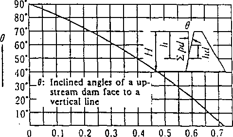
In addition, when the upstream face is of a gentle gradient and a special study is required to find the dynamic pressure, Zangar’s formula can be used:
Pd=CwokH
where C,„: Value of C when EPd becomes maximum
(refer to Fig. 2.14-1)
In Zangar’s formula, the total dynamic pressure (EpJ above the depth of water (/i), and the height from (h(/) to a working point of total dynamic pressure can be expressed as follows:
C
Epd = a uakPF sec 6 hd = ,0h
and a, 0 can be obtained from Fig. 2.14-2.
When a dam’s upstream face consists of a vertical face and an inclined face, the inclined angle (0) in Zangar’s .formula is as follows:
. When the vertical height of the dam’s upstream face is more than
1/2 the dam’s height, the whole upstream face is regarded as vertical.
. When the vertical height of the dam’s upstream face is less than 1/2
the dam’s height, the following gradient is used, i.e. the gradient of a straight line connecting a point where the dam’s upstream face intersects the water level with a point where the above face intersects the‘foundation level.
k: Seismic intensity of design
r: Seismic period (s)
g: Acceleration of gravity (m/s2)
H: Water depth from reservoir water level to foundation ground (m)
5. Dynamic pressure during earthquake
The dynamic pressure acting on a gate leaf can be determined from . the Westergaard formula:
pd - ^k ^/Hh
where Pd: Dynamic pressure (tf/m2)
uj0: Unit weight of water (tf/m3) k'. Seismic intensity of design H\ Water depth from reservoir water level to foundation ground (m) (wave height by wind and earthquake not included)
A: Water depth from reservoir water level to a given point (m)
The external force acting on the bank includes dynamic pressure in addition to the inertial force during the earthquake.
In order to determine the dynamic pressure, the Westergaard formula or the Zangar empirical formula is often used. However, here Westergaard’s simplified formula is shown. This formula was originally derived from conditions when an upstream dam face is vertical, but if the upstream face higher than 1/2 the total depth is almost vertical, the Westergaard’s formula can be used.

Fig. 2-14-1 0-Cm Curve

Fig. 2-14-2 a— ■■ Curve and (3— Curve H H
Seismic intensities for design should be determined based on the actual situation depending upon the type of dam and region, etc. In Japan, however, the values in Table 2.14-1 should be employed.
Table 2.14-1 Seismic Intensities for Design
Type of |
—— Region dam --—_ |
Violent seismal area |
Medium seismal area |
Weak seismal area |
Concrete gravity darn |
0.12 |
0.12 |
0.10 |
|
Arch (.lain |
0.24 |
0.24 |
0.20 |
|
Fill , dam |
Dam dike with almost uniform materials |
0.15 |
0.15 |
0.12 . |
|
Others |
0.15 |
0.12 |
0.10 |
Seismic intensities should be around the values in Table 2.14-2, taking account of areas, conditions of foundation grounds and types of dam. But the seismic intensities for design more than those listed Table 2.14-2 should be decided, taking account of the earthquake occurence in the past of the area and the dynamic characteristics of the dam, when big earthquakes had ever taken place at the site concerned or frequently occurred or there exist some geographical problems. In this case, a seismic stability may be studied by the dynamic analysis in addition to the seismic method described in this standard. When the water level just upstream of a non-overflow part at an arched concrete-dam is surcharge water level, the seismic intensities can be half those in Table 2.14-2.
When the gate of an arch dam is installed at a place other than the dam, the intensities can be more than half those in Table 2.14-1.
Table 2.14-2 Seismic Intensities for Design
1 |
Conditions of dam I Foundation ■ i |
Concrete gravity dam. Hollow gravity dam |
Arch dam |
Rock Till dam |
iiarth fill dam |
|
Normal bedrock [ foundation |
0.12 — 6.15 |
0.24-0.30 |
0.15 |
0.15-0.18 |
Violent seismal area |
Bedrock Foundation having a conspicuous weathering and fracturing or Neocene unconsolidated sediments |
0.15 |
— |
0.15-0.18 |
0.20 - 0.22 |
|
Gravel foundation, soil foundation |
|
— |
0.20 |
0.25 |
- |
Normal bedrock foundation |
0.12 |
0.24 |
0.12-0.15 |
0.15 |
Medium seismal area |
Bedrock foundation having a conspicuous weathering and fracturing or Neocene unconsolidated sediments |
i 0.15 i i |
— |
0.15 |
0.18 |
|
Gravel foundation, soil foundation |
— |
— |
0.18 |
0.22 |
• |
Normal bedrock foundation |
0.10-0.12 |
0.20-0.24 |
0.10-0.12 |
0.12 |
Weak . seismal area |
Bedrock foundation having a conspicuous weathering and fracturing or Neocene unconsolidated sediments Gravel foundation, soil foundation |
i 1 j 0.12 1 1 |
— |
0.12 0.15 |
« 0.15 1 0.18 |
Inertia force during earthquake
An inertia force during earthquake acting on the gate leaf should be the value obtained by multiplying the weight of the gate leaf by the seismic intensity. This force acts horizontally.
The seismic intensity used for a structural calculation of a gate for a movable weir should be 0.12 for violent or medium seismal areas, and 0.10 for weak seismal areas.
The seismic intensity for design of a hydraulic gate installed on top of a dam should be a seismic intensity of the dam different from the
above value.
The seismic intensity for design upward and downward is not normally considered, but if this directional earthquake force is considered to greatly influence the stability of a hydraulic gate it should be included in the study.
• 71 Wind load
A wind load is assumed to act on a clear projected area, and can be obtained by multiplying the following value by shape factors.
for a vertical projected area 300kgf/m2
where shape factor is:
FOR 1
Chapter 1 STEEL PENSTOCKS 7
Section 1 General 7
Section 2 Design 4
Description, 19
2. Material and Allowable Stress 31
Description: 31
3. Pressure Lining Part 46
P‘=2-59£-7&: . 48
(cwlT+U^V.- 51
Description: 56
4. Attachment Installations 91
Description: 97
Section 3 Manufacture 101
Section 4 Installation 107
Section 5 Maintenance 119
Section 6 Anchor Block and Support 127
Chapter 2 HYDRAULIC GATE 137
Section 2 Outline of Design 153
2. Gate Leaf, Gate. Guide and Anchorage 162
Description: 196
Description: 201
3. Gate Hoist 201
Description: 202
Description: 205
Description: 206
Description: 206
Description: 210
Section 3 Design Particulars 213
1. Fixed Wheel Gate 213
Description: 223
—~p 223
F=p.r(q + Pb)Ll 224
2. Radial Gate 225
Description: 225
Description: 226
Description: • 1 228
3. Long Span Gate 229
Description: 221
4. Bottom Hinge Flap Gate 222
Description: 222
Description: 224
5. High Pressure Gates and Valves 226
Description: 226
Description: 229
6. Selective Water Withdrawal Equipment and Surface Water Withdrawal Equipment 235
Description: 235
Description: 236
Description: 236
7. Trash Rack 240
Description: 241
Section 4 Manufacture 245
Description: * 245
Description: 245
Section 5 Installation 246
Description: ' ' : ''f. .1.... ' .a? a ' 247
Description: 247
Description: 248
Description: 254
Description: 256
Section 6 Inspection 257
Description: 258
Section 7 Maintenance 259
Description: 259
Description: 259
Description: 259
Description: 260
Description:. - 260
Description: 261
Description: 261
Description: 262
Description: 262
. Chapter 3 STEEL STRUCTURE 269
Description: 269
Description: 269
Section 2 Design 269
Description: 270
Description: 270
Description: 270
Description: - ■ ' 271
Description: 273
Chapter 4 WELDING 274
Section 1 General 274
Description: 274
Description: - 277
Description: 292
Section 2 Welded Joint 296
Description: 296
Description: 289
Description: 293
Description: ".'A • 295
Description: 297
Description: 298
Description: ; ■ 300
Section 3 Welding Procedure 302
Description: 302
Description: 305
Description: 307
Description: 308
Description: 309
Description: 309
Description: 311
Description: 313
Description: 313
f 313
Description: 315
Description: 323
Section 4 Heat Treatment 327
Section 5 Test and Inspections 334
» Description: 335
Description: 336
Chapters 340
RIVETED, HIGH STRENGTH BOLTED AND BOLTED CONNECTIONS 340
Section 1 General 340
19. Description: 358
79. Description: Omitted 352
81. Description: Omitted 352
84. Description: Omitted 352
111. Description: 354
193. Description: 359
198. . Section 4 Bolted Connections 361
217. Chapter 6 SAFETY AND SANITATION 365
/8. Snow load
The snow load is largely different depending on each area. The rough, values are as follows:
Less compact snow which has just fallen 150 (kgf/m3) Slightly compacted snow 300 (kgf/m3)
Compacted snow or snow which has absorbed a large amount of water 500 — 700 (kgf/m3) / 9. Ice pressure
Ice pressure should be considered depending on various conditions such as the rising temperature ratio, ice thickness, conditions of both banks at a reservoir, direct sunshine on a frozen ice surface, etc. Am example of the above is shown in Fig. 2.14-2.