

TECHNICAL STANDARDS
FOR
GATES AND PENSTOCKS.
HYDRAULIC GATE AND PENSTOCK ASSOCIATION
It is sincerely hoped that the recently revised edition will serve the purpose of assisting those engineers who are engaged in construction and administration of hydraulic gates and penstocks overseas.
Chairman of the Technical Committee Hydraulic Gate and Penstock Association
Table of Contents
FOR 1
Chapter 1 STEEL PENSTOCKS 7
Section 1 General 7
Section 2 Design 4
Description, 19
2. Material and Allowable Stress 31
Description: 31
3. Pressure Lining Part 46
P‘=2-59£-7&: . 48
(cwlT+U^V.- 51
Description: 56
4. Attachment Installations 91
Description: 97
Section 3 Manufacture 101
Section 4 Installation 107
Section 5 Maintenance 119
Section 6 Anchor Block and Support 127
Chapter 2 HYDRAULIC GATE 137
Section 2 Outline of Design 153
2. Gate Leaf, Gate. Guide and Anchorage 162
Description: 196
Description: 201
3. Gate Hoist 201
Description: 202
Description: 205
Description: 206
Description: 206
Description: 210
Section 3 Design Particulars 213
1. Fixed Wheel Gate 213
Description: 223
—~p 223
F=p.r(q + Pb)Ll 224
2. Radial Gate 225
Description: 225
Description: 226
Description: • 1 228
3. Long Span Gate 229
Description: 221
4. Bottom Hinge Flap Gate 222
Description: 222
Description: 224
5. High Pressure Gates and Valves 226
Description: 226
Description: 229
6. Selective Water Withdrawal Equipment and Surface Water Withdrawal Equipment 235
Description: 235
Description: 236
Description: 236
7. Trash Rack 240
Description: 241
Section 4 Manufacture 245
Description: * 245
Description: 245
Section 5 Installation 246
Description: ' ' : ''f. .1.... ' .a? a ' 247
Description: 247
Description: 248
Description: 254
Description: 256
Section 6 Inspection 257
Description: 258
Section 7 Maintenance 259
Description: 259
Description: 259
Description: 259
Description: 260
Description:. - 260
Description: 261
Description: 261
Description: 262
Description: 262
. Chapter 3 STEEL STRUCTURE 269
Description: 269
Description: 269
Section 2 Design 269
Description: 270
Description: 270
Description: 270
Description: - ■ ' 271
Description: 273
Chapter 4 WELDING 274
Section 1 General 274
Description: 274
Description: - 277
Description: 292
Section 2 Welded Joint 296
Description: 296
Description: 289
Description: 293
Description: ".'A • 295
Description: 297
Description: 298
Description: ; ■ 300
Section 3 Welding Procedure 302
Description: 302
Description: 305
Description: 307
Description: 308
Description: 309
Description: 309
Description: 311
Description: 313
Description: 313
f 313
Description: 315
Description: 323
Section 4 Heat Treatment 327
Section 5 Test and Inspections 334
» Description: 335
Description: 336
Chapters 340
RIVETED, HIGH STRENGTH BOLTED AND BOLTED CONNECTIONS 340
Section 1 General 340
19. Description: 358
79. Description: Omitted 352
81. Description: Omitted 352
84. Description: Omitted 352
111. Description: 354
193. Description: 359
198. . Section 4 Bolted Connections 361
217. Chapter 6 SAFETY AND SANITATION 365
Article 21. Rigidity, Minimum Plate Thickness
FOR 1
Chapter 1 STEEL PENSTOCKS 7
Section 1 General 7
Section 2 Design 4
Description, 19
2. Material and Allowable Stress 31
Description: 31
3. Pressure Lining Part 46
P‘=2-59£-7&: . 48
(cwlT+U^V.- 51
Description: 56
4. Attachment Installations 91
Description: 97
Section 3 Manufacture 101
Section 4 Installation 107
Section 5 Maintenance 119
Section 6 Anchor Block and Support 127
Chapter 2 HYDRAULIC GATE 137
Section 2 Outline of Design 153
2. Gate Leaf, Gate. Guide and Anchorage 162
Description: 196
Description: 201
3. Gate Hoist 201
Description: 202
Description: 205
Description: 206
Description: 206
Description: 210
Section 3 Design Particulars 213
1. Fixed Wheel Gate 213
Description: 223
—~p 223
F=p.r(q + Pb)Ll 224
2. Radial Gate 225
Description: 225
Description: 226
Description: • 1 228
3. Long Span Gate 229
Description: 221
4. Bottom Hinge Flap Gate 222
Description: 222
Description: 224
5. High Pressure Gates and Valves 226
Description: 226
Description: 229
6. Selective Water Withdrawal Equipment and Surface Water Withdrawal Equipment 235
Description: 235
Description: 236
Description: 236
7. Trash Rack 240
Description: 241
Section 4 Manufacture 245
Description: * 245
Description: 245
Section 5 Installation 246
Description: ' ' : ''f. .1.... ' .a? a ' 247
Description: 247
Description: 248
Description: 254
Description: 256
Section 6 Inspection 257
Description: 258
Section 7 Maintenance 259
Description: 259
Description: 259
Description: 259
Description: 260
Description:. - 260
Description: 261
Description: 261
Description: 262
Description: 262
. Chapter 3 STEEL STRUCTURE 269
Description: 269
Description: 269
Section 2 Design 269
Description: 270
Description: 270
Description: 270
Description: - ■ ' 271
Description: 273
Chapter 4 WELDING 274
Section 1 General 274
Description: 274
Description: - 277
Description: 292
Section 2 Welded Joint 296
Description: 296
Description: 289
Description: 293
Description: ".'A • 295
Description: 297
Description: 298
Description: ; ■ 300
Section 3 Welding Procedure 302
Description: 302
Description: 305
Description: 307
Description: 308
Description: 309
Description: 309
Description: 311
Description: 313
Description: 313
f 313
Description: 315
Description: 323
Section 4 Heat Treatment 327
Section 5 Test and Inspections 334
» Description: 335
Description: 336
Chapters 340
RIVETED, HIGH STRENGTH BOLTED AND BOLTED CONNECTIONS 340
Section 1 General 340
19. Description: 358
79. Description: Omitted 352
81. Description: Omitted 352
84. Description: Omitted 352
111. Description: 354
193. Description: 359
198. . Section 4 Bolted Connections 361
217. Chapter 6 SAFETY AND SANITATION 365
Chapter 1 STEEL PENSTOCKS
Section 1 General
Article 1. Application
This standard is applicable to steel penstocks to be used for all hydroelectric power stations.
Description:
This standard is applicable only to so-called steel penstocks defined in Article 2., and is not applicable to reinforced concrete pipes or wooden - pipes, etc.
Hydroelectric power stations have a wide variety of sizes and scales ranging from big ones having large capacities and high heads to small ones utilizing streams, but no matter how small-scaled a hydroelectric power station is, there is no difference in design whatsoever for steel penstocks, and thus this standard is applicable to all hydroelectric power stations.
Article 2. Definition
Steel penstocks referred to in this standard mean structures installed to guide water directly from intakes, head tanks or surge-tanks to hydraulic turbines, i.e. steel penstocks consist of penstocks to be pres-
. sure lining parts and their attachment installations (excluding linings r just for the purpose of preventing water leakage).
Pressure Lining Parts referred to in this standard mean pipe shells of steel penstocks.
Attachment installations referred to in this standard mean those listed below:
Expansion joint
Manhole
Air pipe and air valve
Guard valve and its by-pass pipe and by-pass valve
Drainage pipe and drainage valve
Supporting structure
Stiffener and others closely related to the pressure lining part (37 J’^yoA
A Longitudinal Joint referred to in this standard means an axial joint subjected to circumferential forces.
A Circumferential Joint referred to in this standard means a joint in a circular direction, subjected to axial forces.
Description:
‘Guide water directly’ means a pipeline to guide water from an intake to a hydraulic turbine or a pipeline from a head tank or surge-tank to a hydraulic turbine, in a dam type power station or a dam and conduit type j?ower station where a surge-tank is omitted due to a short conduit, and such hydraulic pressure pipes as syphons etc., installed in a headrace between an intake and a head tank or a surge-tank are excluded from this standard.
A pipeline which is provided only for the purpose of preventing water leakage installed in bedrocks between a head tank or a surge-tank and a hydraulic turbine is also excluded because such a pipeline’s design conditions are different from those in this Chapter. ,
Terms of ‘steel lining’, ‘hydraulic pressure pipe’, etc., similar to ‘ steel - penstock’ in this standard are specified in Article 2., Chapter 3.
Omitted
A guard valve is installed either halfway of the steel penstock or at the inlet of a hydraulic turbine, and. the former is called a penstock valve £nd the latter an inlet or main valve in Japan.
‘Something closely related to a pressure lining part especially’ means branch pipes, cooling pipes diverging from a steel penstock and a structure working together with a pressure lining part, and influencing greatly on its strength.
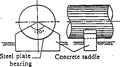
Supporting structures can systematically be expressed as follows:
r—Saddle
support —
Support
Supporting
r~
structure of—
exposed pipe
Supporting
structure of_ steel penstock
(Movable
part) — Steel plate bearing _ ■ —Concrete bearing, —Others
(Support)
Concrete saddle. Steel saddle - Others
*—Ring
support
.
, (thrust collar/ Anchor anchor band/ block anchor
bolt inclusive)
Supporting
.-Filling concrete
(Movable
part) —Rocker bearing . —Roller bearing - — Slide bearing t
—Pin bearing
(Support)
Ring
girder ‘
embedded
LGround
(embedded underground)
pipe
Example
of saddle support
Ring
girder
Ring
girder leg
Rocker
bearing
Bearing
Support
Example
of ring support
Fig.
1.2-1 Example
of Support![]()
![]()

Section 2 Design
7. General
Article 3. Design of Steel Penstock
A steel penstock shall be designed taking account of not only safety but also its economy and workability.
Description :
Steel penstocks, one of the most important structures in a hydroelectric power station, should be designed to be most economical, taking account of their workability' and maintainability based on the securing of safety of the installations. Penstocks, however, are positioned in the whole plan of a hydroelectric power station ranging from an intake to an outlet, and thus it is hard to evaluate steel penstocks from only their economic, "A * *
viewpoint. Therefore, steel penstocks should be generally reviewed and studied in terms gf route, number of lines, diameter, etc., under various conditions derived Jro pa a hydroelectric power station plan. *
Steel penstocks should be designed taking the following factors into consideration:
Type of power station
Power stations in terms of generating system can be grouped into general hydroelectric power stations of either run-of-river type or reservoir type and pumped storage power stations. Dependent upon these power station types, annual operating hours greatly differ.
In deciding on the scale of steel penstocks, an economical design is necessary taking these conditions into consideration and in planning a pumped storage power station of large scale and fewer_annuai
operating hours compared with a general hydroelectric power station, emphasisjs placed on a decrease in construction cost.
Route
It is desirable that steel penstocks be straight,.taking account of conditions of topography, geology and environment. A longitudinal gradient should be selected so that the penstock is below the hydraulic gradient line even if the water level of the intake installation, head tank or surge-tank is lowest, and should be selected so as not to produce negative pressures with fluctuating loads.
Type of steel penstock
Type of steel penstocks.can be classified as exposed and embedded pipes. In either type, the penstock should support all of the internal pressure basically,'but part of the pressure can be shared with surrounding bedrocks in case of an embedded pipe, provided that there exists no problem in structure and material of pipes, and . topography, geology and bedrock conditions be well-known.
Construction works of steel penstock
In a pumped storage power station having a high head and a large capacity, the construction work of steel penstocks may influence the progress of the entire construction schedule of a power station because embedded pipes are often used, thus requiring a design emphasizing its construction work.
Number of pipelines and branch position
As the construction cost of steel penstocks increases in proportion to thenumber-otlines. it is thus desirable, if the lines are long, to decrease the number by installing branches at proper positions, taking the availability of material into consideration.'
Diameter
Diameter of steel penstocks should be decided taking account of economy of the installations and workability, etc.
Materials
Materials used for steel penstocks should be those specified in JIS in principle, and special attention should be paid to the weldability of 70 and 80 kg/mm2 class high tensile steels, thick plates, /■ forging steels, etc., not specified in JIS.
Repair and replacement of existing installations.
In designing repair and replacement of existing steel penstocks, this standard should be applied in principle. But, in case that it is hard to apply this standard due to the conditions of the existing installations and the topography and so forth, the existing installations can effectively be used after reviewing their safety.
Economical diameter
Economical diameters of steel penstocks can be determined taking account of their construction cost, and loss of electric power and energy. Approximate values of an economical penstock diameter can be determined as follows. This method and these calculation formulae have been used so far.
An economical diameter is determined so that the sum of the construction cost and the decrease in power generating power due to loss Of-head* in steel penstocks may become to be minimum.
Friction head loss is calculated usually as the most influential factor, but a joint, reducing, bend and branehjaortjons should also be of structure with a minimum loss.
There are several ways in determination, however, two methods are stated hereinafter: one based on the cost of steel penstock; the other based on the total cost of the penstock and the hydraulic turbine generator. . •
(1) Formulae: Considering cost of the steel penstocks
Qp
Tpyi
VpQ3
(1)

n 5><78,V ^3/ ,
+y) R2' (e.r + e^r.)
2) Any portion (where a thickness of steel penstock is determined by design pressures)
D
( 5x78,4/0*
_
(1
+y)
•IsQgtQiyi
+ Q^yiTg) +
VpQ3
J.
(2)


where £>' Diarnetec of steel penstock (m)
/: Friction loss coefficient.
X: Ratio of the sum of operation and maintenance cost and interest of construction cost of power station over the total construction cost g : Accelen&on of gravity ( = 9.8m/s2)
Cp\ Uoitcost of steel penstock construction (yen/tf)
■ /v; Specific gravity of steel penstock ( = 7.85) t: Thickness of steel penstock (m) y: Ratio of weight increase by stiffeners, etc. of steel penstocks ( = 0.10 — 0.25)
: Combined efficiency of a hydraulic turbine and a generator during power generation
Q_: Discharge used, during power generation (mVs).
 Qi:
Reduction ratio of transmission loss (kW) during power generation
Qi:
Reduction ratio of transmission loss (kW) during power generation
Qi: Reduction ratio of transmission loss (kWh) during ' power generation <
Vi ’• kW price (yen/kW) ' -
7i: kWh price (yen/kWh)
Tt: Annual power generating hours (h) -
Qp: Discharge during pumping-up (m3/s)
Tp: Annual pumping hours (h)
y3: kWh cost for pumping-up (yen/kWh)
tjp: Combined efficiency of pump and motor during - pumping-up
: Reduction ratio of reception loss (kWh) during pumping-up
<p : Joint efficiency of steel penstock
a: Allowable stress of steel penstock (kgf/cm2) p : Design pressure (kgf/cm2)
(2) Formulae: Considering total cost of the steel penstock and hydraulic turbine generator
In the previous formulae, the construction cost only for steel penstocks is taken into consideration but manufacturing cost for the hydraulic turbine and generator are excluded. But the fly-wheel effect of a generator GD2 and a steel penstock design may be changed depending upon how to determine the momentary speed variation zJzi, the momentary pressure variation AP of the hydraulic turbine and the required closing time of the governor. Thus, the • ' most economical penstock diameter can be determined by incorporating the above factors, as follows:
GD2
=
Cp/i(l+j)L2G(GD2)ul«
± —;
2
Qm 2
+ eq
![]()
![]()
![]()

![]()
![]()
An2)
364/^1+-^
e=
v
Mr
(3)-3
GD2
.
2e
e
(3)-4
Ap
=
(3)-5


where GD2: Generator’s fly-wheel effect required for hydraulic turbine (tf-m2)
L: Length of steel penstock (m) (GD2)/ Normal GD1 given by a manufacturer without considering the requirement for a hydraulic turbine (tf/m2)
# Ct: Construction cost per ton of a generator (yen/tf) .Wu: Generator weight usually given by output (tf) Qm: Annual mean discharge (m’/s) e: Dead time of governor (s)
Ve: Propagation velocity of water hammer (m/s) Ap : Momentary pressure variation
: Runaway speed increase ratio of hydraulic turbine = ( runawa? ^eed ~ N)
N
* An : Momentary speed variation of hydraulic turbine Limit of An is 45% for Francis turbine and 60% for Kaplan turbine from mechanical strength, but 40% should be the limit taking voltage regulation into consideration.
A7: Revolutions of turbine (r.p.m.)
K\ Coefficient (= 0.8-0.9)
T: Required closing time for turbine governor (s) u : Average velocity of steel penstock (m/s) H: Hydrostatic pressure (m)
D should be obtained from formula (3)-l, and GD2 from formula (3)-2 by assuming AP, and T should be gotten by substituting GDZ for (3)-4. Then, if the value of AP substituted for (3)-5 is equal to the value of AP assumed in(3)-2, it is satisfactory. In case that GD required for a turbine obtained from (3)-2 is larger than that of the generator itself (i.e.CG-D2)^), the GD required for the turbine should be reduced so that GD becomes equal to (GZ)2)^, or (GD)u of the generator itself should be increased.
As the construction cost for a hydraulic turbine and a generator increases in proportion to GD, an increase in (GZFju means an increase in'the construction cost of a generator, whilst a decrease in GD2 with a constant momentary speed variation of a turbine results in shortening the required closing time, enlarging the momen- . tary pressure variation AP, and increasing the shell thickness of steel penstocks, and thus the construction cost of the penstocks increases. Consequently, which should be selected must be based on a comparison of the economic factors. Contrary to the above, when the GD required for a turbine is smaller than the (GD2)^ o-f the generator itself, an economical penstock diameter should be determined by increasing the momentary pressure variation to lessen the GD2, and by increasing the average velocity with a smaller diameter until requirement of the original design is matched with the construction cost.
Article 4. Design Internal Pressure
The internal pressure to be used for designing shall be the maximum value foreseeable in consideration of the hydrostatic pressure and the pressure risejdue to wateMiammering^and surging.
Description:
Internal pressures working in steel penstocks are. jn_addjtion to the hydrostatic pressure, pressure variations caused by surging in a surge-tajik and water hammering in penstocks generated by turbine load variation. Steel penstocks should be safe from the maximum internal pressure possible to be generated.
When sumjningjjp the pressure rises both by surging and by water hammering, the maximum value which can take place simultaneously should be taken. In casejaLa simple surge-tank, however, it is permissible to consider that the pressure rise by water hammering does not overlap on the
pressure rise by surging. In such a case, it should be noted that “hydrostatic pressure + pressure rise by surging” may become larger than “hydrostatic pressure + pressure rise by water hammering” at the upper portion of a penstock.

Fig. 1.4-1 Example of Design Internal Pressure
(Example of simple surge-tank)
The hydrostatic pressure should be the difference of the heights from the center of the penstock or the hydraulic turbine (the tangent line of the runner in the case of a Pelton turbine) to the crest top of the head tank in the case of a run of river type-power station, and to the maximum design water level of the reservoir or regulating reservoir in the case of a dam or dam^and conduit type, power statinn.
The maximum pressure rise due to surging should be the difference of the .heights from the maximum overflow level to the crest top of a head tank for a run-of-river type and for types with a surge-tank the difference of heights from the maximum water level in the surge-tank to the maximum design water level of the reservoir or regulating pondage at shutting-off in all loads under generating condition.
The pressure rise due to water hammering d£pends_on, the efficiency of the surge-tank, closing equipment, pressure regulator, and pipeline constants, etc. But the maximum value takes place at the center of the closing equipment. (The maximum value is produced in a guide vane for a Francis turbine and in a needle valve for a Pelton turbine,-but the center
1 iJ. f
aexc*/\(g_(n _ io -
tv?) S' -r J-VUnJ- # LLc .ulwt
of the turbine should be assumed in computation.) It gradually_reduces along a pipeline, and vanishes in a head tank or surge-tank. It is assumed . that the reducing ratio of pressure rise by water hammering is propor- tional to the length of the pipeline. The places where the pressure rise by water hammering vanishes should be as follows:
. (a) Head tank, simple surge-tank : place where the water surface expands
Differential surge-tank : overflow top of a riser
Chamber surge-tank : place where the water surface expands if an upper chamber exists; for others at the shaft overflow top
But, in case that a surge-tank is relatively slender or of the restricted orifice type, the pressure rise does not vanish at the surge-tank bottom, and thus the pressure rise should be determined by calculation. The pres-
sure rise by water hammering at the center of a Pelton turbine should be faken as-more than UWof the hydrostatic pressure, despite less than 10% in computation.
It should be noted that the pressure rise by water hammering may sometimes be larger under partial loading than under maximum loading. For
mulae for the pressure rise due to the water hammering without pressure
regulators are classified into the following (A) and (B) depending upon Allievi’s pipeline constant q:
Notations
_ auo 6'2gHo 2L0 |
Allievi’s pipeline constant Closing time constant of a closing equipment |
n= q/6
where ha : Pressure rise due to water hammering at a closing equipment (m)
Hq : Hydrostatic pressure after entirely shutting, off a closing equipment at the turbine end (m)
Lq : Length of pipeline (m)
v’o = |
= : Average velocity (m/s) |
|
A '2 As |
|
/ - 11 - . |
where /,•: Pipe length of velocity ui (m)
u,: Velocity of length li (m/s)
T: Closing time of a closing equipment (s) g : Acceleration of gravity (m/s2)
a : Propagation velocity of pressure wave (m/s)
(A) In case of q > 1:
when |
A-^50% HO ~ |
A_ Ho |
n 1 ri— yln-l-jn2 + 4 |
(1) |
when |
A-<50% |
ho |
2n |
|
rro |
Ho~ |
2 — n |
(2) |
|
when |
He |
ho . Ho^ |
l.lOn |
• "(2)' |
(B) |
In case of q < 1: |
|
|
- |
|
ha' In |
|
|
|
|
l + n(4-l) |
|
|
V-A |
Conditions of (A) and (B) are those similar to Schlag’s, formula (1) is'Allk-d‘s and (2) is Ssurrre’s. Formulae (2)'and (3) are called Calame- Gadeu's formulae too.
■ For a Francis turbine, the following empirical formula applicable to both (A) and (B) conditions is proposed:
K=S^+u5)n (4)
' Pressure rise by the water hammering with a pressure regulator may biCdleulftted by formula (5) taking account of the effect of the pressure regulator if its actual function is clear (in case of replacing existing steel penstocks, thorough consideration should be given to reliability of the pressure regulator), but in this case, at least more than 50% of the value calculated on ano-press arc-regulators basis should be taken.'
In this case, the formula for pressure rises due to the water hammering is as follows:
![]()
![]()
![]()
where r = '
T •
t: Difference in time between the start of a guide vane’s closing and the start of a pressure regulator’s operation(s) But, in this case, the pressure rise does not decrease from'the turbine to a place (L — ).
2 ' * ■
Examples of calculation of the pressure rises and actual measurements are listed in Table 1.4-1:
Tabic 1.4-1 Examples of Calculation of Pressure Rises and Actual Measurements
A. Pressure rises with pressure regulators inoperative
Power station |
Load |
n |
e |
0 |
Calculated value °7o |
Actual measure- meats |
||||||
Formula (1) |
(I)”4 |
Formula (2) |
Formula (2)' |
Formula (3) |
Formula (4) |
|||||||
Power |
kW 1,212 |
0.227 |
7.10 |
1.61 |
25.4 |
- |
25.6 |
25.0 |
19.1 |
29.3 |
27.8 |
|
station |
1,908 |
0.239 |
9.59 |
2.29 |
26.9 |
— |
27.1 |
26.3 |
15.7 |
30.6 |
32.0 |
|
T*1 |
2,220 |
0.247 |
10.7 |
2.64 |
27.9 |
|
28.2 |
27.2 |
14.6 |
31.4 |
31.4 |
|
|
2,532 |
0.225 |
13.6 |
3.06 |
25.2 |
— |
25.4 |
24.8 |
11.7 |
28.4 |
26.4 |
|
Power |
1/4 |
0.145 |
1.53 |
0.222 |
15.5 |
27.1 |
15.6 |
|
26.9 |
23.9 |
33.1 |
|
station |
2/4 |
0.217 |
2.23 |
0.484 |
24.1 |
28.8 |
24.3 |
|
34.3 |
32.0 |
30.1 |
|
H*2 |
3/4 ■ |
0.260 |
2.43 |
0.632 |
29.6 |
29.1 |
29.9 |
|
37.9 |
37.6 |
32.7 |
|
B. Pressure rises with pressure regulators operating
Power station |
Load |
Calculated v? ue, formula (5) °7o |
Actual measurement % |
Power station H*3 |
1/4 |
6.4 |
6.7 |
|
2/4 |
6.0 |
9.2 |
|
3/4 |
6.3 |
9.3 |
Power station S |
1,600 kW |
27.5 |
22.2 |
|
3,000 |
26.9 |
24.0 |
|
3,000 |
13.1 |
16.1 |
|
3,000 |
21.6 |
24.4 |
|
4,500 |
14.3 |
17.8 |
|
4,500 |
19.9 |
17.3 |
|
6,000 |
31.6 |
29.5 |
|
10,000 |
52.5 |
37.1 |
Dimensions of power stations
|
Power station T |
Power station H |
Power station S |
L? m Ho m |
110.8 |
600 |
217 |
38.33 . |
292 |
43 |
|
Q m3/s |
8.35 |
14 |
26 |
5mm |
1,900 |
2,500-1,300 |
3,600-2,700 |
Output kW |
2,400 |
36,000 |
9,000 |
|
Differential surge-tank |
•Conduit type |
Note: ‘1 With q > 1, (1), (2), (2)’, and (4) can be applied the values by (1), (2) and (2)’ are similar, and those by (4) are somewhat larger and are close to the actual measurements.
*2 With p < 1, calculated values by (3) and (4) show good results.
*3 Compared with *2, an effect of a pressure regulator isshown.
*4 Values by Allicvi’s sequential method.
In some cases, actual measurements of the pressure rises by water hammering may differ 10 to 15% from the calculated values, under the influence of turbine characteristics, and thus it is desirable to take about 20% allowance. The above formula (4) includes a 2O°7o allowance.
It is necessary to make either a graphical solution or sequential calculation in the cases below:
For branches, when the furcate point is far away from the hydraulic turbine compared with the pipeline length.
When rising of water level by surging is rapid as in the case of a differential surge-tank. (In many cases' formulae (1) to (5) are applicable.)
In case of restricted orifice surge-tanks (Jaeger’s formula may be used also.)
In case of pump turbines
Reversible pump turbines are mostly employed as main machinery at a pumped storage power station in Japan. The characteristic of ■ the water hammering in this case is that the pressure variation in ■ transient operations is far greater than values calculated from Al- . lievi’s formula. The main reason for this is'that the non-linearity of Q/'/H to the time is more remarkable in case of pump turbines compared with the case of ordinary turbines..
Article 5. Design External Pressure
As for design external pressures of steel penstocks, the maximum pressures which may take place during drainage, when a pipeline is empty, - as well as under construction shall be taken into consideration.
Description:
Various pressures act on steel penstocks such as negative pressures during drainage, seepage pressures of bedrocks working on embedded portions, . and concrete pressures and grout pressures' during construction works. A steel penstock must be of a structure capable of withstanding maximum external pressures possible to take place taking the above into consideration.
’ In orderjo, prevent collapse due to the negative pressure of a pipeline during drainage, air pipes or air valves are installed. Since they are designed to ensure to introduce the amount of air required with less than - 0.2kg/cm2 pressure difference between the inside and outside pipe, normally 0.2kgf/cm2 of pressure difference between the inside and outside pipe should be taken into consideration for exposed pipes. (See Article 26.) This is not necessary, however, when air comes in freely during drainage, i.e. negative pressures cannot take place.
Seepage pressure of bedrocks should be external pressures due to under- . ground water level expected, but its design pressure can be reduced when drainage installations are provided around the steel penstocks to reduce the external pressures.
Deformation of penstocks due to the concrete pressures during construction works should be prevented by means of jigs inside the penstocks, other supports, or stiffeners, etc.
Structural calculations may be made for concrete pressures and grout pressures during construction works, together with including corrosion allowance. In this case, it is permissible to prevent the deformation by . inside supports.
Article 6. Head Loss
Pressure lining parts and attachment installations of steel penstocks shall be designed hydraulically to keep the head losses to a minimum as much ^s possible.
Description:
Head losses in steel penstocks have a large percentage of the total head tosses of a power station.
The number and diameter of a penstock should be decided economically from the relationship of the electric .power loss due to head losses ■and the cohstructibn cost as. in Article 3. Head losses are influenced not Ohly by friction losses of steel penstocks but also by branches, .bend pipes, educing pipes, inlet pipes, expansion joints, guard valves, etc., to some extent, and thus considerations should be given to the design of these structures so as to minimize head losses as much as possible.
It should be noted that the influence of the head loss is great for a power ration having a low head and a big capacity. Important head losses for pipelines can be calculated as follows:
4« Friction Head Loss
h - f _ 2gn 2
J J ' R* 2g' J R'n
.. wh€r€ hf: Friction head loss (m)
n : Kutter’s coefficient of roughness^,
L: Length of pipe (m)
v : Flow velocity (m/s)
R : Hydraulic depth of pipe (m) g: Acceleration of gravity (m/s2)
O
For circular pipes, taking D as the internal diameter of the pipe: f = 124.5n2 R D*”
. •
As for the valuebf n, 0.010 to 0.014 is applicable to normal steel pipes. 2» Head losses of entrance, reducing, enlarging, and bending
CKCukc'-t
-
16 -
" 1. .. -
r - J,'.... (
3. Other head losses
Other head losses of diverging (joining) should be based on the description of Article 22., this Chapter. '
Table 1.6-1 Head Loss
Type
of head loss
Entrance
head loss
Calculation
formula
Remarks
where:
ht
: Entrance head loss ft
: Entrance loss coefficient
V
: Flow velocity after flowing-in
Type
of entrance Square cornered - - Cut cornered _»?—• Rounded
(circular) Rounded (rectangular) Bell mouth of 1/4 ellipse
J
e
0.25
0.1
0.2
—
0.01-0.05
b*.
Reducing
head loss
where:
htt
: Reducing head loss ftc
: Reducing loss coefficient
V
: Flow velocity after reducing
Enlarging
head loss
h
D
■' 2g
where:
htf
: Enlarging head loss
flt
: Enlarging loss
coefficient
K,
: Flow velocity before enlarging
K,
: Flow velocity after enlarging
Enlarging
loss coefficient![]()
![]()


![]()
Type
of
head loss
Bending
head
loss
Calculation
formula
Remarks
V1
~
fbl ’ fbl '
2g
where:
hb
: Bending head loss
fbi
:
Loss coefficient determined by the ratio of bending radius q
to the pipe diameter D
(q/D),
in case that a , center angle of bending is 90°. (See Fig.
(a))
fbi
: Ratio of the loss for a center angle 6
to the loss for a center angle of 90° (See Fig. (b))
V.
:
Flow velocity The following empirical formula is frequently
used for and /M:
A,
= 0.131 + 0.1632
hb
given by the above formula does not include the friction head
loss.
p/D
(a)
Value of (6 = 90°)![]()
![]()


Head loss of a valve differs in hydraulic characteristics depending on each design, and so the loss coefficient should be decided appropriately to its characteristics. ' \£
Slight head losses are generated around expansion joints, manholes, etc., and so it is desirable to add some allowances to the sum of head loss.
![]()
Article 7. Consideration for Water Quality
When the pH value of water in a steel penstock is less than 4, some measures shall be taken to decrease the corrosion of the steel penstock.
Description,
In volcanic zones, there may exist rivers having corrosive water due to sulfurous acid gas, etc., produced there. '
Corrosion progress due to corrosive water is affected by hydrogen ion exponent (pH), specific conductivity, amount of chlorine ions, etc. Generally, pH is used as the index for corrosion progress.
Generally, steel corrosion due to acid water develops very rapidly with a pH value of less than 4.5 and develops especially significantly with a pH of less than 4.0. Steel corrosion progress is hardly affected by a pH value from 4.5 to 10.
Corrosion due to acid water is greatly influenced by the flow velocity and inflow of soil and sand, and thus it should be noted that corrosion may develop when flow velocity and inflow of soil and sand are excessive even if the pH is more than 4.
The value of the pH differs depending upon the flow rate of the river. When the flow rate is high in a wet season, the pH values become relatively high with the acid water diluted and thus the minimum pH values should be taken as a criteria throughout the year.
Table 1.7-1 Example of Actual Measurement in Agatsuma River
.. Power station |
Test place |
Flow velocity in pipe (m/s) |
pH (1965.4 - 1966.3) |
|
Mean value |
-Min. value to Max. value |
|||
Matsuya |
Sukawa intake |
2.77 - 3.15 |
6.2 |
4.5 - 7.8 |
• Kanai |
Head tank |
2.51 - 4.80 |
5.5 |
4.7 - 7.1 |
Saku |
Aficrbay |
1.40 - 3.85 |
5.7 |
5.0 - 7.6 |
Actual measurements made in Agatsuma River in Japan by Tokyo Elec-'
; trie Power Co., Inc. are shown in Table 1.7-1. As a result of the measurements, corrosion barely develops with more than 4.4 pH and with a little flow velocity and less inflow of soil and sand, but it becomes clear that corrosion is prompted widely and remarkably with less than 4.0 pH and 1 ~ 2m/s flow velocity.
Some measures to prevent corrosion are available. One method is to
..a';
paint an acid resisting material or make a lining to the pipe inside, and the other one is to produce a pipe itself using an acid resisting steel. Field tests have been conducted concerning rivers with acid water by Central Research Institute of Electric Power Industry and various electric power companies in Japan.
According to the above researches, chlorinated rubber paint and alkyd resin type paint show excellent properties. Tar-epoxy resin type as a paint using the excellent properties of the epoxy resin has been widely used in recent years.
Stainless steels are superior as acid resisting steel and are used as clad steel from an economic viewpoint.
Corrosion of steel penstocks by acid water develops very rapidly when steel penstocks are worn by flowing sands. In such a case, it is necessary to decrease the corrosion of penstocks by making a lining made of a coal tar enamel having much resistance to wear; or by attaching patches (made of acid resisting steel) to the bottom of pipes or portions subjected to much Influence of corrosion Wear, as well as by preventing the sands from flowing in.