

Метод Т-матриц / 21.09083101
.pdfProgress In Electromagnetics Research, PIER 96, 309{328, 2009
CHARACTERIZATION OF THE VALIDITY REGION OF THE EXTENDED T-MATRIX METHOD FOR SCATTERING FROM DIELECTRIC CYLINDERS WITH FINITE LENGTH
W. Z. Yan and Y. Du
The Department of Information Science and Electronics Engineering
Zhejiang University
Hangzhou 310027, China
Z. Y. Li and E. X. Chen
Institute of Forest Resources Information Techniques
Chinese Academy of Forestry
Beijing 100091, China
J. C. Shi
Institute for Computational Earth System Sciences
University of California
Santa Barbara, CA 93106, USA
Abstract|The T-matrix approach is e®ective in analyzing electromagnetic scattering from ¯nite scatterers. Yet for scatterers with extreme geometry, this approach may fail. One example is its inability to analyze scattering from dielectric cylinders with large aspect ratios. To deal with such di±culty, recently we proposed a method based on an extension of the T-matrix approach, where a long cylinder is hypothetically divided into a cluster of identical sub-cylinders, for each the T matrix can be numerically stably calculated. Special care was paid to ful¯ll the boundary conditions at the hypothetic surface of any two neighboring sub-cylinders. The resultant coupled equations are di®erent from that of multi-scatterer theory. The model results were in good agreement with experiment data available in the literature. However, the validity region of the proposed method was not fully characterized. Now we have developed and validated a method of moment (MoM) code, and are in a position to carry on the task of
Corresponding author: Y. Du (zjuydu03@zju.edu.cn).
310 |
Yan et al. |
characterizing the validity region. The proposed method is found to be applicable to dielectric cylinders of arbitrary length as long as the T matrix is attainable for the elementary sub-cylinder. The conditions for the T matrix to be numerically stably calculated in terms of the equivalent volumetric radius and relative dielectric constant are also empirically obtained.
1. INTRODUCTION
The electromagnetic scattering by canonical physical objects is important in many applications [1{8]. For the case of dielectric cylinder with ¯nite length, an exact analytical solution is still elusive, and several approximation approaches have been proposed in the literature. One popular approach is the generalized Rayleigh-Gans (GRG) approximation [9, 10], where the induced current in the cylinder is approximated by that of in¯nite length. This method is valid for a needle shaped scatterer with radius much smaller than the wavelength. It should be noted that solutions of such approximate methods in general fail to satisfy the reciprocity theorem.
On the other hand, a semi-analytical method called the T-matrix approach [11] is based on the extended boundary condition method (EBCM), with the T matrix being used to relate the exciting ¯eld and scattered ¯eld, where the exciting ¯eld is assumed to be inside the inscribing sphere and the scattered ¯eld outside the circumscribing sphere, respectively. The T-matrix approach is gaining popularity due to its rigor and powerfulness and has been applied to scattering from objects of various shapes, such as spheroids, ¯nite cylinders, Chebyshev particles, cubes, clusters of spheres, and so on [12{17].
However, in treating scattering from dielectric cylinder of ¯nite length, if any of the parameters including length, equivalent volumetric radius, and relative dielectric constant is adequately large, then the T-matrix approach may su®er from slow convergence or even fail to converge [18]. With a focus on ensuring convergence for dielectric cylinders with large aspect ratio (the ratio of length to diameter of a cylinder), recently we have proposed a new iterative technique with extension to the T-matrix approach [19], where a long cylinder is hypothetically divided into a cluster of identical sub-cylinders, for each the T matrix can be numerically stably calculated. Special care was paid to ful¯ll the boundary conditions at the hypothetic surface of any two neighboring sub-cylinders. The resultant coupled equations are di®erent from that of multi-scatterer theory. The model results were in good agreement with experiment data available in the literature.
Progress In Electromagnetics Research, PIER 96, 2009 |
311 |
However, the validity region of the proposed method was not fully characterized. To this end, we have developed and veri¯ed a MoM code, which is based on the combined-¯eld integral equation (CFIE) with Galerkins procedure [20], and are in a position to carry on the task of characterizing the validity region. The proposed method is found to be applicable to dielectric cylinders of arbitrary length as long as the T matrix is attainable for the elementary sub-cylinder. The conditions for the T matrix to be numerically stably calculated in terms of the equivalent volumetric radius and relative dielectric constant are also empirically obtained.
2. T-MATRIX APPROACH
In T-matrix approach, the incident, scattered, and internal ¯elds are expressed in terms of the spherical harmonics, respectively
Einc |
¡ |
r¹0 |
¢ |
= n;m namninc(M)RgM¹mn |
|
¡ |
r¹0 |
¢ |
+ amninc(N)RgN¹mn |
r¹0 |
¢ |
o |
|||||
|
|
X |
|
|
|
|
|
o |
¡ |
|
|
||||||
Esca |
¡ |
r¹0 |
¢ |
= n;m namnsca(M)M¹mn |
r¹0 |
¢ |
+ amnsca(N)N¹mn |
r¹0 |
|
|
|
|
(1) |
||||
|
|
X |
¡ |
|
|
|
¡ |
¢ |
|
|
|
|
o |
||||
Eint |
¡ |
r¹0 |
¢ |
= n;m namnint(M)RgM¹mn |
|
r¹0 |
¢ |
+ amnint(N)RgN¹mn |
r¹0 |
¢ |
|||||||
|
|
X |
|
|
¡ |
|
|
|
|
¡ |
|
|
|||||
|
|
¹ |
¹ ¹ |
|
¹ |
|
|
|
|
|
|
|
|
|
|
||
where RgMmn, RgNmn, Mmn and Nmn are the vector spherical waves |
|||||||||||||||||
respectively as de¯ned in [25]. Owing to the linearity of Maxwell's equations and boundary conditions, the linear relation between the scattered ¯eld coe±cients a¹sca and the incident ¯eld coe±cients a¹inc can be related by a system transfer operator called T-matrix as follows [11]:
sca |
¹ |
inc |
: |
(2) |
a¹ |
= T a¹ |
|
Note that matrix T in (2) contains the full information about the wave scattering and absorption properties of a object. A very attractive feature of the T-matrix approach is that, unlike many other methods of analyzing scattering where the entire calculation needs to be repeated for each new incident ¯eld, the T matrix only needs to be calculated once because it is independent of any speci¯c incident ¯eld. Moreover, utilizing geometrical symmetries of scatterers can drastically reduce CPU-time requirements.
In analyzing scattering from dielectric cylinders of ¯nite length, the applicability of the T-matrix approach depends on the frequency of the incidence wave, and describing parameters of the cylinder including length, equivalent volumetric radius, and relative dielectric
312 |
Yan et al. |
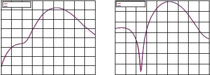
constant. When none of the describing parameters is large, the T- matrix method is applicable [18]. One example is shown in Fig. 1 where the theoretical results of T-matrix method for both vertical and horizontal polarization bistatic scattering cross section are in agreement of that of MoM. In this example, the diameter D of cylinder is 2 cm, the length L is 6 cm and the relative dielectric constant ²r is 4 + i. The frequency of the incidence wave is 5 GHz, and the elevation angle of incident wave is 105± and the azimuthal angle is 90±. The cylinder is located at the origin and its symmetric axis is along z axis. In our treatment of MoM, all the surfaces of cylinders are approximated by planar triangular patches where the edge length is set to ¸=8 and the Rao-Wilton-Glisson (RWG) function [21] is chosen as both basis and test functions. The developed code has been tested extensively against FEKO, a commercial software product for the simulation of electromagnetic ¯elds, and excellent agreement is always obtained. One illustration is shown in Fig. 2, where the simulation parameters are as above except L = 11 cm. Both verticaland horizontal-polarized bistatic scattering cross sections almost completely overlap for the developed MoM code and FEKO.
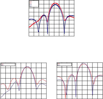
On the other hand, if any of the parameters becomes large, the T-matrix approach may su®er from convergence problem or converges to incorrect values [18]. For example, if we keep the same con¯guration as that of the example in Fig. 1 except that the length is enlarged to 11 cm, then we would be alarmed to observe that the predictive power of the T-matrix method has drastically degraded (see Fig. 3).
|
-15 |
T matrix Method |
|
|
|
|
|
||
|
|
|
|
|
|
|
|||
|
|
MoM |
|
|
|
|
|
|
|
|
-20 |
|
|
|
|
|
|
|
|
|
-25 |
|
|
|
|
|
|
|
|
(dB) |
-30 |
|
|
|
|
|
|
|
|
-35 |
|
|
|
|
|
|
|
|
|
vv |
|
|
|
|
|
|
|
|
|
|
|
|
|
|
|
|
|
|
|
σ |
-40 |
|
|
|
|
|
|
|
|
|
|
|
|
|
|
|
|
|
|
|
-45 |
|
|
|
|
|
|
|
|
|
-50 |
|
|
|
|
|
|
|
|
|
-55 |
|
|
|
|
|
|
|
|
|
0 |
20 |
40 |
60 |
80 |
100 |
120 |
140 |
160 180 |
|
|
|
|
|
θs (Degree) |
|
|
||
(a) Vertical polarization
|
-20 |
T matrix Method |
|
|
|
|
|
|
|
|
|
|
|
|
|
|
|
||
|
|
MoM |
|
|
|
|
|
|
|
|
-25 |
|
|
|
|
|
|
|
|
|
-30 |
|
|
|
|
|
|
|
|
(dB) |
-35 |
|
|
|
|
|
|
|
|
|
|
|
|
|
|
|
|
|
|
hh |
|
|
|
|
|
|
|
|
|
σ |
-40 |
|
|
|
|
|
|
|
|
|
|
|
|
|
|
|
|
|
|
|
-45 |
|
|
|
|
|
|
|
|
|
-50 |
|
|
|
|
|
|
|
|
|
-55 |
|
|
|
|
|
|
|
|
|
0 |
20 |
40 |
60 |
80 |
100 |
120 |
140 |
160 180 |
|
|
|
|
|
θs (Degree) |
|
|
||
(b) Horizontal polarization
Figure 1. The bistatic scattering cross section of a circular cylinder under conventional T-matrix method and MoM where the length is 6 cm and diameter is 2 cm.
Progress In Electromagnetics Research, PIER 96, 2009 |
313 |
|
-10 |
σvv by MoM |
|
|
|
|
|
|
|
-15 |
σvv by FEKO |
|
|
|
|
|
|
|
σhh by MoM |
|
|
|
|
|
|
|
|
|
σhh by FEKO |
|
|
|
|
|
|
|
-20 |
|
|
|
|
|
|
|
|
-25 |
|
|
|
|
|
|
|
(dB) |
-30 |
|
|
|
|
|
|
|
-35 |
|
|
|
|
|
|
|
|
|
|
|
|
|
|
|
|
|
|
-40 |
|
|
|
|
|
|
|
|
-45 |
|
|
|
|
|
|
|
|
-50 |
|
|
|
|
|
|
|
|
-55 |
|
|
|
|
|
|
|
|
0 |
20 |
40 |
60 |
80 |
100 |
120 140 |
160 180 |
|
|
|
|
|
θs (Degree) |
|
||
Figure 2. The bistatic scattering cross section of a circular cylinder under the developed MoM code and FEKO where the length is 11 cm and diameter is 2 cm.
|
-10 |
T matrix Method |
|
|
|
|
|
|
-15 |
||
|
|
MoM |
|
|
|
|
|
|
|
|
|
|
-15 |
|
|
|
|
|
|
|
|
|
-20 |
|
|
|
|
|
|
|
|
|
|
|
|
|
-20 |
|
|
|
|
|
|
|
|
|
-25 |
|
|
|
|
|
|
|
|
|
|
|
|
(dB) |
-25 |
|
|
|
|
|
|
|
|
(dB) |
-30 |
|
|
|
|
|
|
|
|
|
|||
|
|
|
|
|
|
|
|
|
-35 |
||
vv |
|
|
|
|
|
|
|
|
|
hh |
|
-30 |
|
|
|
|
|
|
|
|
|
||
σ |
|
|
|
|
|
|
|
|
σ |
-40 |
|
|
|
|
|
|
|
|
|
|
|||
|
|
|
|
|
|
|
|
|
|
|
|
|
-35 |
|
|
|
|
|
|
|
|
|
-45 |
|
|
|
|
|
|
|
|
|
|
|
|
|
-40 |
|
|
|
|
|
|
|
|
|
-50 |
|
|
|
|
|
|
|
|
|
|
|
|
|
-45 |
|
|
|
|
|
|
|
|
|
-55 |
|
0 |
20 |
40 |
60 |
80 |
100 |
120 |
140 |
160 180 |
|
0 |
|
|
|
|
|
θs (Degree) |
|
|
|
|
||
(a) Vertical polarization
T matrix Method
MoM
20 40 60 80 100 120 140 160 180
θs (Degree)
(b) Horizontal polarization
Figure 3. The bistatic scattering cross section of a circular cylinder under conventional T-matrix method and MoM where the length is 11 cm and diameter is 2 cm.
3. BRIEF DESCRIPTION OF THE PROPOSED ITERATIVE METHOD
It is understood that in the conventional form of the T-matrix formalism, its applicability to scattering from dielectric cylinders of ¯nite length is limited. Any attempt to extend the range of applicability of the T-matrix approach starts from an analysis of the characteristics of the issues at hand. In earth observation using microwave remote sensing means, when tree or crop constituents such as trunks, stems or branches are typically modelled as dielectric cylinders of ¯nite length (e.g., [22, 23]), their diameters or relative
314 Yan et al.
dielectric constants are in general within the reach of T-matrix method at L, C or X band. The major concern is the large aspect ratio. To this end we have recently developed a new iterative technique with extension to the T-matrix approach [19] which we shall brie°y describe as follows.
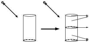
In this method, an elongated cylinder is ¯rst divided into a cluster of N identical sub-cylinder by using N ¡1 hypothetic surfaces, for each the T matrix can be calculated stably in the numerical sense. Then special care is paid to both rigorously ful¯ll the boundary conditions at the hypothetical division interfaces and cast the coupling among sub-cylinder into a rigorous formulism. For illustration purpose, the case of two sub-cylinder division is considered here (Fig. 4). Since the EBCM involves surface integrals and since cylinder division generates hypothetical interfaces, these surfaces need to be denoted carefully before we proceed. Each sub-cylinder will contain a primary surface and an interface. We shall start number ordering from the lowest subcylinder (see Fig. 4). The center of sub-cylinder j is rj. The primary surface of sub-cylinder j(j = 1; 2), Sjp, includes its surface without the
division interface. The common interface is denoted by S12. |
|||||||||||||
"amn(N)(j)v |
# |
|
¡ ¡ |
Z |
|
½ |
|
£ |
|
|
¢ ·N¹¡mn(rrj)¸ |
||
(M)(j)v |
|
|
|
|
|
|
|
|
|
|
|
|
¹ |
amn |
|
= |
ik( 1)m |
dS |
i!¹n^j |
|
Hj(r) |
M¡mn(rrj) |
|||||
|
|
|
|
|
Sv |
¢ ·M¹¡mn(rrj)¸¾ |
|
||||||
|
|
|
|
j £ j |
|
|
|||||||
|
|
|
+kn^ |
|
E (r) |
|
¹ |
|
|
|
|
(3) |
|
"amns(N)(j)v # |
|
|
|
N¡mn(rrj) |
|
||||||||
|
¡ |
Z |
½ |
|
£ |
|
|
¢ ·RgN¹¡mn(rrj)¸ |
|||||
s(M)(j)v |
|
|
|
|
|
|
|
|
|
|
|
|
¹ |
amn |
|
= |
ik( 1)m dS |
|
i!¹n^j |
|
Hj(r) |
|
RgM¡mn(rrj) |
||||
|
|
|
|
|
Sv |
|
|
¹ |
|
|
|
|
|
|
|
|
+kn^ |
|
E |
(r) |
|
|
|
|
(4) |
||
|
|
|
j £ |
|
RgN¡mn(rrj) |
||||||||
|
|
|
|
j |
|
¢ ·RgM¹¡mn(rrj)¸¾ |
|||||||
Because the boundary conditions at the division interface of each sub-cylinder are pointwise while the EBCM is in an integral form and should be carefully incorporated into the EBCM formalism, thus for such concern, we introduce some intermediate variables that have speci¯c meanings, where the ¯elds are expanded in terms of vector spherical waves with di®erent origins and the boundary conditions are incorporated. Such variables are expressed in (3) and (4), where the superscript v(v = p; d) denotes the primary part (p) or common interface (d) of the jth sub-cylinder, and corresponding Sv denotes Sjp or S12, respectively. s denotes the scattered ¯eld. In the above, n^j is the outward pointing unit normal vectors on the surface Sj of subcylinder j. These intermediate variables are not arbitrary quantities
Progress In Electromagnetics Research, PIER 96, 2009 |
315 |
E |
i |
E i |
|
|
|
Primary |
(S2p) |
|
|
Surface |
|
|
|
Contact (S12) |
|
|
|
Surface |
|
|
|
Primary |
(S1p) |
|
|
Surface |
|
Figure 4. Division of a cylinder into two identical sub-cylinder.
but have speci¯c physical meanings. They represent the expansion coe±cients of the exciting ¯elds and scattered ¯elds due to the primary surfaces and the interface of these sub-cylinder, respectively. Therefore, utilizing T matrix, the expanded coe±cients a¹mn and a¹smn for each part can be related.
Since the quantities a¹(1)mnu and a¹smn(2)d are expressed in terms of the tangential ¯elds on the interface, it is natural to relate them in some way. Yet since each involves vector spherical waves with di®erent origins, a transformation of origin must ¯rst be performed using the translational addition theorem which is a powerful analytic tool to solve theoretically for the scattering properties of multiple scatterers. For the case of vector spherical wave functions, the vector addition theorems have the form [24]
|
¹ |
¸ = |
|
mn |
|
¹ |
|
|
RgMmn(¹rj) |
¹;º |
RgA¹º (¹rji) |
|
|||
|
·RgN¹mn(¹rj) |
½·RgB¹ºmn(¹rji)¸RgM¹º(¹ri) |
|
||||
|
|
|
X |
RgB¹ºmn(¹rji) |
|
¹ |
|
|
|
|
+ |
|
(5) |
||
|
|
|
mn |
RgN¹º(¹ri) |
|||
and |
|
|
·RgA¹º (¹rji)¸ |
|
¾ |
|
|
¹ |
¸ = |
|
|
|
|
|
|
|
|
mn |
|
¹ |
|
||
|
Mmn(¹rj) |
¹;º |
A¹º (¹rji) |
|
|
||
|
·N¹mn(¹rj) |
½·B¹ºmn(¹rji)¸RgM¹º(¹ri) |
|
||||
|
|
|
X |
B¹ºmn(¹rji) |
¹ |
|
|
|
|
|
+ ·A¹ºmn(¹rji)¸RgN¹º(¹ri)¾ |
(6) |
|||
for the condition r¹i < r¹ji, where the vector spherical waves with and without the pre¯x Rg stand for regular and outgoing waves, respectively. The formulation and computation of coe±cients Amn¹º and
B¹ºmn also can be found in [24]. Fortunately, for the transformation in
316 |
Yan et al. |
this case we have the convenience of reducing the double summation over m and º to single summation over º because the translation is along the z axis. By shifting the origin from r1 to r2 and making use
of the intermediate variables of sub-cylinder 2, the term a¹(1)mnd be expressed as
amn(M)(1)d |
# |
= |
A¡mº |
(r |
r |
) |
amvs(M)(2)d |
# |
"amn(N)(1)d |
º |
¡mn |
1 |
2 |
|
"amvs(N)(2)d |
||
|
|
½ |
|
|
|
|
|
|
|
|
X |
|
|
|
|
|
|
+B¡¡mnmº |
amvs(N)(2)d |
(r1r2) "amvs(M)(2)d#¾: |
can thus
(7)
Here,we also speci¯cally make use of the boundary conditions n^1 £
H1 = ¡n^2 £ H2 and n^1 £ E1 = ¡n^2 £ E2.
Note that for a single scatterer, the incident ¯eld is equal to the exciting ¯eld. In our case, the virtual partition shall not change this property. Now if we let the global origin coincidence with r1, by applying transformation of origin on the vector spherical waves and making use of the intermediate variables we have
amn(M) |
= |
amn(M)(1)p |
# ¡ |
|
A¡mn(r1r2) |
amºs(M)(2)p |
# |
|
"amn(N) # |
|
"amn(N)(1)p |
|
¡mº |
"amºs(N)(2)p |
|||
|
|
|
º |
|
½ |
|
|
|
|
|
|
X |
|
|
|
|
|
|
|
+B¡mn(r1r2) |
amºs(N)(2)p |
: |
|
(8) |
||
|
|
¡mº |
"amºs(M)(2)p#¾ |
|
|
|||
Combining the above two equations, yields |
|
|
|
|||||
amn(M) |
= |
amn(M)(1) |
# ¡ |
|
A¡mn(r1r2) |
amºs(M)(2) |
|
|
"amn(N) # |
|
"amn(N)(1) |
|
¡mº |
"amºs(N)(2) # |
|||
|
|
|
º |
|
½ |
|
|
|
|
|
|
X |
|
|
|
|
|
|
|
+B¡mn(r1r2) |
amºs(N)(2) |
: |
|
(9) |
||
|
|
¡mº |
"amºs(M)(2) |
#¾ |
|
|
||
One notes that (9) is di®erent from that of multi-scatterer theory (MST) [25]. As a matter of fact, the MST is not valid here because its requirement of mutually exclusive circumscribing spheres of the subcylinders is not ful¯lled.
Similarly, we can also establish the following system of equations by focusing on the upper part of cylinder as follows
amn(M)0 |
= |
amn(M)(2) |
A¡mn(r |
r |
) |
amºs(M)(1) |
# |
|||||
(N) |
0 |
|
(N)(2) |
|
mº |
2 |
1 |
|
|
s(N)(1) |
||
"amn |
# "amn |
# ¡ Xº |
|
¡ |
|
|
|
|
"amº |
|||
|
|
|
¡ Xº |
B¡mn(r2r1) |
amºs(N)(1) |
|
; |
(10) |
||||
|
|
|
¡mº |
|
"amºs(M)(1) |
# |
|
|||||
Progress In Electromagnetics Research, PIER 96, 2009 |
317 |
where the multipole coe±cients of the incident plane wave a(mnM)0 and
di®er from a(mnM) and a(mnN) by a factor eikhcosµi . Here h is the height of each sub-cylinder. Therefore, we can use iterative method to obtain the solution of these coupled, linear, simultaneous equations. The iteration procedure is summarized as follows: Starting with the
initial solutions asmn(M);2 = asmn(N);2 = 0. From (9) and by using T matrix we obtain the new values of the scattering coe±cients a¹s;mn1 in (10). In a similar manner, we next use the new values to obtain the
scattering coe±cients a¹s;mn2 in (9). The procedure is repeated until all the coe±cients converge.
The scattered ¯eld can be treated similarly. Therefore, the total scattered expansion coe±cients of whole cylinder in the primary coordinate system are
amns(M) |
= |
amns(M)(1) |
+ |
RgA¡mn(r1r2) |
amºs(M)(2) |
# |
|
"amns(N) # |
|
"amns(N)(1) # |
Xº |
¡mº |
# |
"amºs(N)(2) |
|
|
|
+ RgB¡mn(r1r2) amºs(N)(2) |
: |
(11) |
|||
|
|
Xº |
¡mº |
"amºs(M)(2) |
|
|
|
In far-¯eld region, for linear polarization the scattering cross |
|||||||
section is de¯ned as |
|
|
|
|
(12) |
||
|
|
¾pq = 4¼ ¯Fpq(k^s; k^i)¯2 ; |
|
|
|||
|
|
|
¯ |
¯ |
|
|
|
|
|
|
¯ |
¯ |
|
|
|
where p^ and q^ are unit polarizations for the incident and scattered wave, respectively. The expression of amplitude scattering matrix
^ ^ |
|
|
|
Fpq(ks; ki) is given by |
X |
½q^ ¢ amns(M)totalM¹mn(kr; µ; Á) |
|
Fqp(k^s; k^i) = |
|
||
m;n |
|
||
|
+^q ¢ amns(N)totalN¹mn(kr; µ; Á)¾ ¢ p^ |
(13) |
|
where the expressions of far-¯eld solutions for the outgoing vector spherical waves can be found in [25]. It should be noted that due to conventional EBCM has been successfully applied to particles of various shapes, the new method can also be used for ¯nite dielectric cylinders with arbitrary cross section as long as the T matrix of each sub-cylinder can be accurately obtained.

318 |
Yan et al. |
4. CONVERGENCE CHECK AGAINST ARBITRARY ASPECT RATIO
From the numerical examples as shown in Fig. 1 and Fig. 3 we observe that applicability of the conventional T-matrix method highly depends on the aspect ratio. Its predictive results go from excellent to erroneous when the aspect ratio goes from 3 to 5:5. It is interesting to characterize the range of the aspect ratio within which the proposed iterative technique is valid.
|
-10 |
Proposed Method |
|
|
|
|
|
|
-15 |
||
|
|
MoM |
|
|
|
|
|
|
|
|
|
|
-15 |
|
|
|
|
|
|
|
|
|
-20 |
|
|
|
|
|
|
|
|
|
|
|
|
|
-20 |
|
|
|
|
|
|
|
|
|
-25 |
|
|
|
|
|
|
|
|
|
|
|
|
(dB) |
-25 |
|
|
|
|
|
|
|
|
(dB) |
-30 |
|
|
|
|
|
|
|
|
|
|||
|
|
|
|
|
|
|
|
|
-35 |
||
vv |
|
|
|
|
|
|
|
|
|
hh |
|
-30 |
|
|
|
|
|
|
|
|
|
||
σ |
|
|
|
|
|
|
|
|
σ |
-40 |
|
|
|
|
|
|
|
|
|
|
|||
|
|
|
|
|
|
|
|
|
|
|
|
|
-35 |
|
|
|
|
|
|
|
|
|
-45 |
|
|
|
|
|
|
|
|
|
|
|
|
|
-40 |
|
|
|
|
|
|
|
|
|
-50 |
|
|
|
|
|
|
|
|
|
|
|
|
|
-45 |
|
|
|
|
|
|
|
|
|
-55 |
|
0 |
20 |
40 |
60 |
80 |
100 |
120 |
140 |
160 180 |
|
0 |
|
|
|
|
|
θs (Degree) |
|
|
|
|
||
(a) Vertical polarization
Proposed Method
MoM
20 |
40 |
60 |
80 |
100 |
120 |
140 |
160 180 |
θs (Degree)
(b) Horizontal polarization
Figure 5. The bistatic scattering cross section of a circular cylinder under our proposed method and MoM where the length is 11 cm and diameter is 2 cm.
|
-5 |
Proposed Method |
|
|
|
|
|
||
|
|
|
|
|
|
|
|||
|
-10 |
MoM |
|
|
|
|
|
|
|
|
|
|
|
|
|
|
|
|
|
|
-15 |
|
|
|
|
|
|
|
|
|
-20 |
|
|
|
|
|
|
|
|
(dB) |
-25 |
|
|
|
|
|
|
|
|
-30 |
|
|
|
|
|
|
|
|
|
vv |
|
|
|
|
|
|
|
|
|
-35 |
|
|
|
|
|
|
|
|
|
σ |
|
|
|
|
|
|
|
|
|
|
-40 |
|
|
|
|
|
|
|
|
|
-45 |
|
|
|
|
|
|
|
|
|
-50 |
|
|
|
|
|
|
|
|
|
-55 |
|
|
|
|
|
|
|
|
|
0 |
20 |
40 |
60 |
80 |
100 |
120 |
140 |
160 180 |
|
|
|
|
|
θs (Degree) |
|
|
||
(a) Vertical polarization
|
-10 |
Proposed Method |
|
|
|
|
|
||
|
|
MoM |
|
|
|
|
|
|
|
|
-20 |
|
|
|
|
|
|
|
|
(dB) |
-30 |
|
|
|
|
|
|
|
|
-40 |
|
|
|
|
|
|
|
|
|
hh |
|
|
|
|
|
|
|
|
|
|
|
|
|
|
|
|
|
|
|
σ |
|
|
|
|
|
|
|
|
|
|
-50 |
|
|
|
|
|
|
|
|
|
-60 |
|
|
|
|
|
|
|
|
|
-70 |
|
|
|
|
|
|
|
|
|
0 |
20 |
40 |
60 |
80 |
100 |
120 |
140 |
160 180 |
|
|
|
|
|
θs (Degree) |
|
|
||
(b) Horizontal polarization
Figure 6. The bistatic scattering cross section of a circular cylinder under our proposed method and MoM where the length is 20 cm and diameter is 2 cm.