


Intel Desktop Board D845EPI Technical Product Specification
1.1 Overview
1.1.1Feature Summary
Table 1 summarizes the major features of the Intel® Desktop Board D845EPI.
Table 1. Feature Summary
Form Factor
Processor
Memory
Chipset
Video
Audio
I/O Control
USB
Peripheral
Interfaces
Expansion
Capabilities
BIOS
Instantly Available
PC Technology
microATX (9.20 inches by 8.20 inches [233.68 millimeters by 208.28 millimeters])
•Support for an Intel® Pentium® 4 processor in an mPGA478 socket with a 400/533 MHz system bus
•Support for an Intel® Celeron® processor in an mPGA478 socket with a 400 MHz system bus
•Two 184-pin DDR SDRAM Dual Inline Memory Module (DIMM) sockets
•Support for single-sided or double-sided DIMMs (DDR333/266/200)
•Support for up to 2 GB system memory
Intel® 845E Chipset, consisting of:
•Intel® 82845E Memory Controller Hub (MCH)
•Intel® 82801DB I/O Controller Hub (ICH4)
•4 Mbit Firmware Hub (FWH)
AGP connector supporting 1.5 V 4X AGP cards
Audio subsystem for AC ‘97 processing using the Realtek ALC202A codec
SMSC LPC47M172 LPC Bus I/O controller or National Semiconductor PC87372 I/O controller
Support for USB 2.0 devices
•Up to six USB ports
•One serial port
•One parallel port
•Two IDE interfaces with UDMA 33, ATA-66/100 support
•One diskette drive interface
•PS/2† keyboard and mouse ports
•Three fan connectors
Three PCI bus add-in card connectors (SMBus routed to PCI bus connector 2)
•Intel/AMI BIOS (resident in the 4 Mbit FWH)
•Support for Advanced Configuration and Power Interface (ACPI), Plug and Play, and SMBIOS
•Support for PCI Local Bus Specification Revision 2.2
•Suspend to RAM support
•Wake on PCI, RS-232, front panel, PS/2 devices, and USB ports
12

Product Description
1.1.2Manufacturing Options
Table 2 describes the manufacturing options on the Desktop Board D845EPI. Not every manufacturing option is available in all marketing channels. Please contact your Intel representative to determine which manufacturing options are available to you.
Table 2. Manufacturing Options
LAN
Hardware Monitor
Subsystem
Intel® 82562ET 10/100 Mbit/sec Platform LAN Connect (PLC) device
•Hardware monitoring and fan control ASIC
•Three fan sense inputs used to monitor fan activity
•Chassis intrusion detection
Serial Port B |
Connector for a second serial port |
For information about
The board’s compliance level with ACPI, Plug and Play, and SMBIOS
Available configurations for the Desktop Board D845EPI
Refer to
Section 1.5, page 17
Section 1.3, page 16
13
Intel Desktop Board D845EPI Technical Product Specification
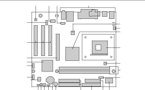
1.1.3Board Layout
Figure 1 shows the location of the major components on the Desktop Board D845EPI.
A |
B |
C |
|
D |
|
|
BB |
|
|
|
|
|
E |
|
|
|
|
|
|
|
|
|
|
|
|
|
F |
|
|
|
|
|
|
G |
AA |
|
|
|
|
|
|
|
|
|
|
|
|
H |
Z |
|
|
|
|
|
|
Y |
|
|
|
|
|
I |
X |
|
|
|
|
|
|
|
|
|
|
|
|
|
|
|
|
|
|
|
J |
W |
|
|
|
|
|
K |
V |
|
|
|
|
|
|
|
U T S R Q P |
O |
N |
M |
L |
|
|
|
|
|
|
|
OM16243 |
A |
Audio codec |
O |
IDE connectors |
B |
Intel 82562ET 10/100 Mbit/sec (PLC) device |
P |
Speaker |
|
(optional) |
|
|
C |
ATAPI CD-ROM connector |
Q |
Battery |
D |
Back panel connectors |
R |
Auxiliary front panel power LED connector |
E |
+12V power connector (ATX12V) |
S |
Front chassis fan connector |
F |
Rear chassis fan connector |
T |
Chassis intrusion connector |
G |
Intel 82845E MCH |
U |
BIOS Setup configuration jumper block |
H |
mPGA478 processor socket |
V |
4 Mbit Firmware Hub (FWH) |
I |
Processor fan connector |
W |
Front panel connector |
J |
DIMM sockets |
X |
Front panel USB connector |
K |
Serial Port B connector (optional) |
Y |
Intel 82801DB I/O Controller Hub (ICH4) |
L |
I/O Controller |
Z |
AGP connector |
M |
Power connector |
AA |
PCI bus add-in card connectors |
N |
Diskette drive connector |
BB |
Front panel audio connector |
|
|
|
|
Figure 1. Desktop Board D845EPI Components
14