- •Preface
- •Intended Audience
- •What This Document Contains
- •Typographical Conventions
- •Contents
- •1 Product Description
- •1.1 Overview
- •1.1.1 Feature Summary
- •1.1.2 Manufacturing Options
- •1.1.3 Board Layout
- •1.2 Block Diagram
- •1.3 Online Support
- •1.4 Operating System Support
- •1.5 Design Specifications
- •1.6 Processor
- •1.7 System Memory
- •1.8 Intel® 845E Chipset
- •1.8.3 IDE Interfaces
- •1.9 I/O Controller
- •1.9.1 Serial Ports
- •1.9.2 Parallel Port
- •1.9.3 Diskette Drive Controller
- •1.9.4 Keyboard and Mouse Interface
- •1.10 Audio Subsystem
- •1.10.1 Audio Connectors
- •1.10.2 Audio Subsystem Software
- •1.11 LAN Subsystem (Optional)
- •1.11.3 LAN Subsystem Software
- •1.12 Hardware Management Subsystem (Optional)
- •1.12.1 Hardware Monitoring and Fan Control ASIC
- •1.12.2 Fan Monitoring
- •1.12.3 Chassis Intrusion and Detection
- •1.13 Power Management
- •1.13.1 ACPI
- •1.13.2 Hardware Support
- •2 Technical Reference
- •2.1 Introduction
- •2.2 Memory Map
- •2.3 Fixed I/O Map
- •2.4 DMA Channels
- •2.5 PCI Configuration Space Map
- •2.6 Interrupts
- •2.7 PCI Interrupt Routing Map
- •2.8 Connectors
- •2.8.1 Back Panel Connectors
- •2.8.2 Internal I/O Connectors
- •2.8.3 External I/O Connectors
- •2.9 Jumper Blocks
- •2.9.1 Front Panel Audio Connector/Jumper Block
- •2.9.2 BIOS Setup Configuration Jumper Block
- •2.10 Mechanical Considerations
- •2.10.1 I/O Shield
- •2.11 Electrical Considerations
- •2.11.1 DC Loading
- •2.11.3 Fan Connector Current Capability
- •2.11.4 Power Supply Considerations
- •2.12 Thermal Considerations
- •2.13 Reliability
- •2.14 Environmental
- •2.15 Regulatory Compliance
- •2.15.1 Safety Regulations
- •2.15.2 EMC Regulations
- •2.15.3 European Union Declaration of Conformity Statement
- •2.15.4 Product Ecology Statements
- •2.15.5 Product Certification Markings (Board Level)
- •3 Overview of BIOS Features
- •3.1 Introduction
- •3.2 BIOS Flash Memory Organization
- •3.3 Resource Configuration
- •3.3.1 PCI Autoconfiguration
- •3.3.2 PCI IDE Support
- •3.4 System Management BIOS (SMBIOS)
- •3.5 Legacy USB Support
- •3.6 BIOS Updates
- •3.6.1 Language Support
- •3.6.2 Custom Splash Screen
- •3.7 Recovering BIOS Data
- •3.8 Boot Options
- •3.8.2 Network Boot
- •3.8.3 Booting Without Attached Devices
- •3.8.4 Changing the Default Boot Device During POST
- •3.9 Fast Booting Systems with Intel® Rapid BIOS Boot
- •3.9.1 Peripheral Selection and Configuration
- •3.9.2 Intel Rapid BIOS Boot
- •3.10 BIOS Security Features
- •4 BIOS Setup Program
- •4.1 Introduction
- •4.2 Maintenance Menu
- •4.3 Main Menu
- •4.4 Advanced Menu
- •4.4.1 PCI Configuration Submenu
- •4.4.2 Boot Configuration Submenu
- •4.4.3 Peripheral Configuration Submenu
- •4.4.4 IDE Configuration Submenu
- •4.4.5 Diskette Configuration Submenu
- •4.4.6 Event Log Configuration Submenu
- •4.4.7 Video Configuration Submenu
- •4.4.8 USB Configuration Submenu
- •4.4.9 Chipset Configuration Submenu
- •4.5 Security Menu
- •4.6 Power Menu
- •4.6.1 ACPI Submenu
- •4.7 Boot Menu
- •4.7.1 Boot Device Priority Submenu
- •4.7.2 Hard Disk Drives Submenu
- •4.7.3 Removable Devices Submenu
- •4.8 Exit Menu
- •5 Error Messages and Beep Codes
- •5.1 BIOS Error Messages
- •5.2 Port 80h POST Codes
- •5.3 Bus Initialization Checkpoints
- •5.4 Speaker
- •5.5 BIOS Beep Codes
Intel Desktop Board D845EPI Technical Product Specification
2.10 Mechanical Considerations
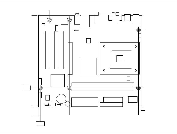
The Desktop Board D845EPI is designed to fit into either a microATX or an ATX-form-factor chassis. Figure 11 illustrates the mechanical form factor for the Desktop Board. Dimensions are given in inches [millimeters]. The outer dimensions are 9.20 inches by 8.20 inches
[233.68 millimeters by 208.28 millimeters]. Location of the I/O connectors and mounting holes are in compliance with the ATX specification.
#INTEGRATOR’S NOTE
When installing the Desktop Board in a microATX chassis, make sure that peripheral devices are installed at least 1.5 inches above the main power connector, the diskette drive connector, the IDE connector, and the DIMM sockets.
.800
[20.32]
6.50
[165.10]
6.10 [154.94] 5.20
[132.08]
0.00 |
|
|
|
1.700 |
|
9.050 |
|
[42.5] |
|
||
.150 |
|
[229.87] |
|
2.600 |
8.800 |
||
[3.81] |
|||
[66.04] |
[223.52] |
||
|
|||
|
0.00 |
|
|
|
|
OM16250 |
Figure 11. Desktop Board Dimensions
56
Technical Reference
2.10.1I/O Shield
The back panel I/O shield for the Desktop Board D845EPI must meet specific dimension and material requirements. Systems based on this Desktop Board need the back panel I/O shield to pass emissions (EMI) certification testing. Figure 12 shows the critical dimensions of the I/O shield. Dimensions are given in inches [millimeters], to a tolerance of ±0.020 inches
[0.508 millimeters].
The figures also indicate the position of each cutout. Additional design considerations for I/O shields relative to chassis requirements are described in the ATX specification. See Section 1.5 for information about the ATX specification.
#INTEGRATOR’S NOTE
An I/O shield compliant with the ATX chassis specification 2.03 is available from Intel.
6.390 Ref
[162.300]
0.787±0.010 TYP [20±0.254]
3x Dia 0.330 [8.380]
0.039 Dia. [1.000]
0.884
[22.450]
0.276
[7.012]
0.00
0.465
[11.811]
0.567
[14.400]
0.00 |
0.447 |
[11.345] |
1.195 |
[30.360] |
1.807 |
[45.892] |
2.079 |
[52.804] |
5.010 |
[127.250] |
5.732 |
[145.584] |
0.063±0.005
[1.600±0.120]
8X R0.5 MIN
0.519
[13.190]
0.027 [0.690] 1.89 0.465 Ref [11.811]
0.567
[14.400]
0.621
[15.770]
Pictorial
View
OM12352
Figure 12. I/O Shield Dimensions
57