


Technical Reference
2.8 Connectors
CAUTION
Only the back panel USB, front panel USB, VGA, and PS/2 connectors have overcurrent protection. The Desktop Boards’ internal connectors are not overcurrent protected and should connect only to devices inside the computer’s chassis, such as fans and internal peripherals. Do not use these connectors to power devices external to the computer’s chassis. A fault in the load presented by the external devices could cause damage to the computer, the interconnecting cable, and the external devices themselves.
This section describes the board’s connectors. The connectors can be divided into these groups:
•Back panel I/O connectors (see page 44)
PS/2 keyboard and mouse
USB (four ports)
Parallel port
Serial port A
LAN (optional)
Audio (line out, line in, and mic in)
•Internal I/O connectors (see page 45)
Audio (ATAPI CD-ROM and front panel audio)
Fans
Power
Add-in boards (PCI)
IDE
Diskette drive
Chassis intrusion
•External I/O connectors (see page 50)
Serial Port B (optional)
Auxiliary front panel power/sleep/message-waiting LED
Front panel (power/sleep/message-waiting LED, power switch, hard drive activity LED, reset switch, and auxiliary front panel power LED)
Front panel USB (one connector for two ports)
NOTE
When installing the board in a microATX chassis, make sure that peripheral devices are installed at least 1.5 inches above the main power connector, the diskette drive connector, the IDE connector, and the DIMM sockets.
43
Intel Desktop Board D845EPI Technical Product Specification
2.8.1Back Panel Connectors
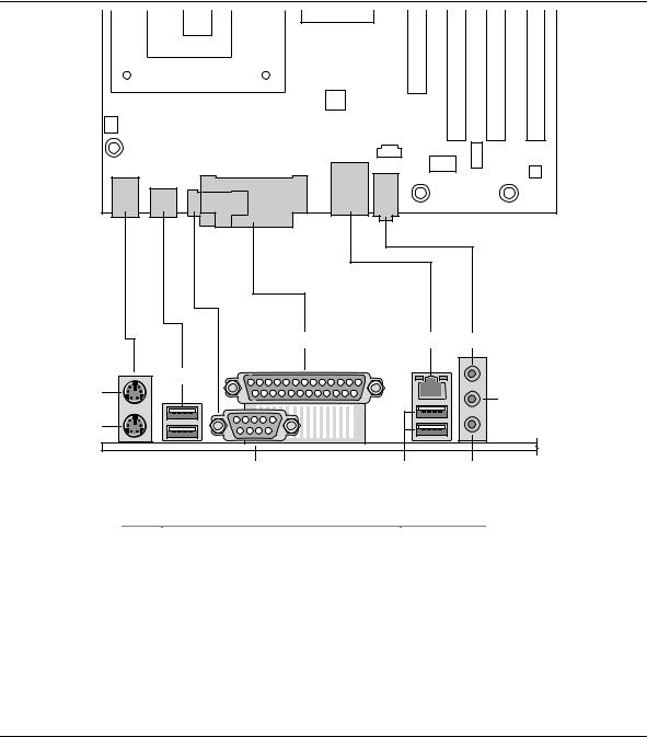
Figure 4 shows the location of the back panel connectors. The back panel connectors are color-coded in compliance with PC 99 recommendations. The figure legend below lists the colors used.
|
E |
F |
H |
A |
C |
|
|
|
|
J |
|
|
|
|
|
B |
|
|
|
|
D |
G |
I |
|
|
|
OM16245 |
Item |
Description |
Color |
|
A |
PS/2 mouse port |
Green |
|
B |
PS/2 keyboard port |
Purple |
|
C |
USB ports |
Black |
|
D |
Serial port A |
Teal |
|
E |
Parallel port |
Burgundy |
|
F |
LAN (optional) |
Black |
|
G |
USB ports |
Black |
|
H |
Audio line in |
Light blue |
|
I |
Mic in |
Pink |
|
J |
Audio line out |
Lime green |
|
Figure 4. Back Panel Connectors
44
Technical Reference
#INTEGRATOR’S NOTE
The back panel audio line out connector is designed to power headphones or amplified speakers only. Poor audio quality occurs if passive (non-amplified) speakers are connected to this output.
2.8.2Internal I/O Connectors
The internal I/O connectors are divided into the following functional groups:
•Audio, power, and hardware control (see page 46)
Front panel audio
ATAPI CD-ROM
Fans (3)
ATX12V power
Main power
Chassis intrusion
•Add-in boards and peripheral interfaces (see page 49)
PCI bus
IDE
Diskette drive
2.8.2.1Expansion Slots
The Desktop Board has three PCI rev 2.2 compliant local bus slots. The SMBus is routed to PCI bus connector 2.
#INTEGRATOR’S NOTE
This document references back-panel slot numbering with respect to processor location on the Desktop Board. PCI slots are identified as PCI slot #x, starting with the slot closest to the processor. The ATX/microATX specifications identify expansion slot locations with respect to the far edge of a full-sized ATX chassis. The ATX specification and the Desktop Board’s silkscreen are opposite and could cause confusion. The ATX numbering convention is made without respect to slot type, but refers to an actual slot location on a chassis. Figure 6 on page 49 illustrates the Desktop Board’s PCI slot numbering.
45

Intel Desktop Board D845EPI Technical Product Specification
2.8.2.2Audio, Power, and Hardware Control Connectors
Figure 5 shows the location of the audio, power, and hardware control connectors.
A B C
1 |
2 |
1 |
|
|
|
9 |
10 |
4 |
|
3
1 2 
 1
1
3 
 4
4
1
3
20 


 11
11
1 |
1 |
3 |
10 |
1 |
D
E
|
|
H G |
F |
|
|
|
|
OM16246 |
|
|
Item |
Description |
For more information see: |
|
|
|
|
|
|
|
A |
Front panel audio |
Table 17 |
|
|
B |
ATAPI CD-ROM (black) |
Table 18 |
|
|
C |
+12 V power connector (ATX12V) |
Table 19 |
|
|
D |
Rear chassis fan |
Table 20 |
|
|
E |
Processor fan |
Table 21 |
|
|
F |
Main power |
Table 22 |
|
|
G |
Front chassis fan |
Table 23 |
|
|
H |
Chassis intrusion |
Table 24 |
|
|
|
|
|
|
Figure 5. Audio, Power, and Hardware Control Connectors
46
Technical Reference
Table 17. Front Panel Audio Connector
Pin |
|
Signal Name |
Pin |
|
Signal Name |
1 |
|
MIC_IN |
2 |
|
Ground |
3 |
|
MIC_BIAS |
4 |
|
+5 V |
5 |
|
RIGHT_OUT |
6 |
|
RIGHT_IN |
7 |
|
No connect |
8 |
|
Key |
9 |
|
LEFT_OUT |
10 |
|
LEFT_IN |
|
|
|
|
|
|
Table 18.
Pin
ATAPI CD-ROM Connector
Signal Name
1Left audio input from CD-ROM
2CD audio differential ground
3CD audio differential ground
4Right audio input from CD-ROM
#INTEGRATOR’S NOTES
•Use only ATX12V-, SFX12V-, or TFX12V-compliant power supplies with this board. ATX12V, SFX12V, and TFX12V power supplies have an additional power lead that provides required supplemental power for the processor. Always connect the 20-pin and 4-pin leads of ATX12V, SFX12V, and TFX12V power supplies to the corresponding connectors on the Desktop Board, otherwise the Desktop Board will not boot.
•Do not use a standard ATX power supply. The Desktop Board will not boot with a standard ATX power supply.
Table 19. ATX12V Power Connector
Pin |
|
Signal Name |
Pin |
|
Signal Name |
1 |
|
Ground |
2 |
|
Ground |
3 |
|
+12 V |
4 |
|
+12 V |
|
|
|
|
|
|
47
Intel Desktop Board D845EPI Technical Product Specification
Table 20. Rear Chassis Fan Connector
Pin
1
2
3
Signal Name
Ground (default) or FNT_REAR_FAN_CTRL (optional)
+12 V
No connect (default) or REAR_TACH_OUT (optional)
Table 21. Processor Fan Connector
Pin |
Signal Name |
1Ground (default) or CPU_FAN_TACH (optional)
2+12 V
3No connect (default) or CPU_FAN_TACH
Table 22. Main Power Connector
Pin |
|
Signal Name |
Pin |
|
Signal Name |
1 |
|
+3.3 V |
11 |
|
+3.3 V |
2 |
|
+3.3 V |
12 |
|
-12 V |
3 |
|
Ground |
13 |
|
Ground |
4 |
|
+5 V |
14 |
|
PS-ON# (power supply remote on/off) |
5 |
|
Ground |
15 |
|
Ground |
6 |
|
+5 V |
16 |
|
Ground |
7 |
|
Ground |
17 |
|
Ground |
8 |
|
PWRGD (Power Good) |
18 |
|
No connect |
9 |
|
+5 V (Standby) |
19 |
|
+5 V |
10 |
|
+12 V |
20 |
|
+5 V |
|
|
|
|
|
|
Table 23. Front Chassis Fan Connector
Pin
1
Signal Name
Ground (default) or FNT_REAR_FAN_CTRL (optional)
2
3
+12 V
No connect (default) or FRONT_FAN_TACH (optional)
Table 24. Chassis Intrusion Connector
Pin |
Signal Name |
1Intruder
2Ground
48
Technical Reference
2.8.2.3Add-in Board and Peripheral Interface Connectors
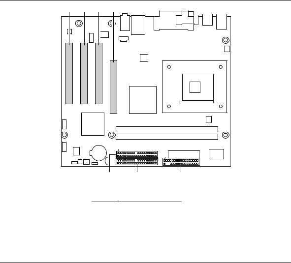
Figure 6 shows the location of the add-in board connector and peripheral connectors for the Desktop Board D845EPI. Note the following considerations for the PCI bus connectors:
•All of the PCI bus connectors are bus master capable.
•SMBus signals are routed to PCI bus connector 2, enabling PCI bus add-in boards with SMBus support to access sensor data on the Desktop Board. The SMBus signals are as follows:
The SMBus clock line is connected to pin A40.
The SMBus data line is connected to pin A41.
A |
B |
C |
D |
|
|
|
|
|
|
2 |
|
|
|
|
|
40 |
|
|
|
|
1 |
39 |
2 |
|
|
|
2 |
40 |
34 |
|
|
|
1 |
39 |
33 |
|
|
|
|
|
1 |
|
|
|
G |
F |
E |
|
|
|
|
|
OM16247 |
|
|
Item |
|
Description |
|
|
|
A |
|
PCI bus connector 3 |
|
|
|
B |
|
PCI bus connector 2 |
|
|
|
C |
|
PCI bus connector 1 |
|
|
|
D |
|
AGP connector |
|
|
|
E |
|
Diskette drive |
|
|
|
F |
|
Primary IDE |
|
|
|
G |
|
Secondary IDE |
|
Figure 6. Add-in Board and Peripheral Interface Connectors
49