

Апсе Нуцлеар Течнологиес 2014
.pdfg (r) = |
m |
= |
P1,2 |
(r) × M1,2 |
. |
|
|
|
|||
1,2 |
V |
|
|
R ×T |
|
|
|
|
|
Then, differential equation (5) can be re-written
|
|
dP1,2 (r) |
= |
P1,2 (r) × M1,2 |
×w2 × r; |
|
|
|
|||
|
|
dr |
|
|
|
|
|||||
|
|
|
R ×T |
|
|
|
|
|
|||
and solved: |
|
|
|
|
|
|
|
|
|||
|
|
M × w2 × r2 |
|
|
|
M × V2 |
|
|
|||
P1,2 |
(r) = P(0) × exp |
|
1,2 |
|
|
= P(0) × exp |
1,2 |
|
; |
||
|
2 × R × T |
2 × R × T |
|||||||||
|
|
|
|
|
|
|
|
||||
|
|
|
|
|
|
|
|
|
|
|
|
where V – linear velocity.
Evidently, content of light and heavy components in the gaseous mixture are proportional to the spatial pressure distribution:
|
|
|
|
|
|
|
|
|
|
MLIGHT × V2 (r) |
||
X |
235 |
(r) = X |
235 |
(0) × exp |
|
|
; |
|||||
|
|
|||||||||||
|
|
|
|
|
|
2 × R × T |
|
|||||
|
|
|
|
|
|
|
|
|
|
|
||
|
|
|
|
|
|
|
|
|
MHEAVY × V2 (r) |
|||
X |
238 |
(r) = X |
238 |
(0) × exp |
|
|
|
. |
||||
|
|
|
||||||||||
|
|
|
|
|
|
2 × R × T |
|
|
||||
|
|
|
|
|
|
|
|
|
|
|
|
|
These formulas demonstrate that content of the heavy component (depleted uranium) is larger in peripheral region of the centrifuge, and, vice versa, content of the light component (enriched uranium) is larger in central region of the centrifuge. In this case, the single-stage enrichment factor can be determined from the following expressions:
71

a= X235 (0) / X238 (0) = exp (-MLIGHT × V2 (r) 2 × R × T) =
(r)X235 (r) / X238 (r) exp (-MHEAVY × V2 (r) 2 × R × T)
= exp (DM × V2 (r) 2 × R × T);
e¢(r) = a(r) -1 » DM × V2 (r) ). 2 × R × T
As is seen, the single-stage enrichment gain ε′ of the GC-technology depends only on absolute, not relative like in the GD-technology, difference of molecular masses of the light and heavy gas components. Also, the single-stage enrichment gain is proportional to the squared linear velocity of the centrifuge rotation. The centrifuges of contemporary designs can rotate with linear velocities up to 500-700 m/s, i.e. near to the velocity of a bullet outgoing from the rifle tube. According to many numerical evaluations, the GC-technology can provide the following velocity-dependent values of the single-stage enrichment gain at the outer centrifuge radius r0:
e′(r0 ) = 0, 068 at V = 330 m / s; e′(r0 ) = 0, 098 at V = 400 m / s; e′(r0 ) = 0,152 at V = 500 m / s;
e′(r0 ) = 0,300 at V = 700 m / s.
The gas centrifuges are currently being made of the following structural materials:
1.Aluminum-based alloys for linear velocities V £ 350 m/s.
2.Titanium-based alloys for linear velocities V £ 450 m/s.
3.Alloyed steels for linear velocities V £ 500 m/s.
4.Glass-fiber plastics reinforced with graphite for linear velocities V
=500-700 m/s.
If vertical gas circulation can be arranged in the centrifuge (for example, by thermal convection caused by temperature gradient between top and bottom parts of the centrifuge), then the centrifuge can act as the enriching cascade. The gaseous mixture goes upwards along
72
central axis and then goes downwards along the centrifuge wall. So, the gaseous mixture of 235UF6 and 238UF6 is being continuously enriched with the heavy component in the peripheral bottom region while the gaseous mixture is gradually enriched with the light component in the central top region of the centrifuge.
The gas flow going upwards in the center and downwards at the periphery can be formed by an insignificant warming-up of the central region. The warming-up effect can be produced by a small electrically heated rod placed in the centrifuge center.
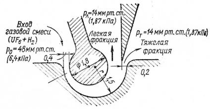
3. The separation-nozzle technology of uranium enrichment
The separation-nozzle (SN) technology has been developed at the Karlsruhe Nuclear Research Center (Germany) as an alternative to the GDand GC-technologies. The gaseous mixture UF6 and hydrogen (or helium) expands along a bent wall. The centrifugal deflection force can split the flow into the light and heavy fractions by means of a slimmer (Fig. 8).
|
|
|
|
|
|
|
|
PL=14 mm Hg |
|
|
|
|
||||
|
|
|
|
|
|
|
|
|
|
|
|
|
|
|
|
|
|
|
Gaseous |
|
|
|
|
|
|
|
|
|
|
|
|
||
|
|
|
|
|
|
|
|
|
|
|
|
|
|
|||
|
|
mixture |
|
|
|
|
|
|
Light |
|
|
PH = 14 mm Hg |
||||
|
|
|
|
|
|
|||||||||||
|
|
(UF6+H2) |
|
|
|
|
|
fraction |
|
|||||||
|
|
|
|
|
|
|
|
|
|
Heavy |
|
|||||
|
|
|
|
|
|
|
|
|
|
|
||||||
P0 = 48 mm Hg |
|
|
|
|
|
|
||||||||||
|
|
|
|
|
|
|
|
fraction |
|
|||||||
|
|
|
|
|
|
|
|
|
|
|
|
|
|
|
|
|
|
|
|
|
|
|
|
|
|
|
|
|
|
|
|
|
|
Nozzle
Fig. 8. Layout of the separation-nozzle technology
The hydrogen or helium auxiliary gas increases the flow velocity and, hence, it increases the centrifugal forces defining efficiency of the SN-process.
73
The SN-technology is profitably distinguished from the GCtechnology by the absence of the rotating details but it requires a very fine mechanical assemblage because of very little sizes of the splitting slits (decimal fractions of one millimeter). The single-stage enrichment gain in the SN-technology can reach ε′ ≈ 0, 025 at the specific energy consumption about 3000 kWh/SWU.
4. The laser technologies of uranium enrichment
The laser technologies of uranium enrichment rely on the slightly different excitation energies of electronic shells that surround 235U and 238U nuclei. Three extra neutrons in 238U nucleus caused the slight shift in the electron excitation energy scheme as compared with 235U nucleus. This energy shift can be used to excite selectively uranium atoms or uranium-containing molecules by the monochromatic laser light properly tuned to the required wavelength. The excited state of electronic shell can selectively enhance some physical or chemical processes with uranium-containing materials and, thus, promote isotope separation.
The following conditions should be satisfied for successful implementation of the laser-induced isotope separation:
1.The energy spectrum of the excited electronic levels must contain a line belonging to one isotope only, and this line must be sufficiently far from other spectral lines of the desirable isotope and from all spectral lines of other isotopes.
2.Physical or chemical processes must be found which are able to separate the excited and non-excited uranium-containing components.
3.Laser-induced impact on the isotopic composition to be separated must be a main excitation mechanism, not inter-atomic or intermolecular collisions.
4.High-efficiency lasers must be developed and finely tuned to the appropriate wavelength.
Presently, the following two laser isotope separation technologies are under intense development and demonstration, namely atomic vapor laser isotope separation (AVLIS) and molecular laser isotope separation (MLIS).
74
4.1. AVLIS-technology
The AVLIS-technology has been developed at the Lawrence Livermore National Laboratory (USA). The AVLIS technology includes the following stages:
1.Vacuum evaporation of uranium atoms at very high temperature (~23000C). Beam of accelerated electrons knocks uranium atoms out of uranium-rhenium alloy.
2.Irradiation by xenon laser (l~3780 Å, ultraviolet range). 235U atoms are selectively excited.
3.Irradiation by krypton laser (l~3500 Å, ultraviolet range). The excited 235U atoms are selectively ionized.
4.Collection of 235U ions on an electrically charged plate.
4.2. MLIS-technology
The MLIS-technology has been developed at the Los Alamos National Laboratory (USA). The MVLIS technology includes the following stages:
1.Expansion of gaseous uranium hexafluoride – hydr ogen composition through a hypersonic nozzle. As a result, uranium hexafluoride cools down to about 30 K but it does not condense.
2.Irradiation by infrared laser (l~1,6·105 Å). Molecules of 235UF6 are selectively excited.
3.Irradiation by ultraviolet laser (l~3,08·104 Å). The excited
molecules of 235UF6 are selectively dissociated with the formation of uranium pentafluoride 235UF5 and free fluorine:
2 × 235 UF6 ® 2 × 235 UF5 + F2 .
Uranium pentafluoride 235UF5 precipitates from the gas flow as a fine powder (so called, “laser snow”) that can be easily collected.
The single-stage enrichment factors are very high for both laser technologies of uranium enrichment. They cover the range from 3 to 15, according to different experimental studies. Such high-efficiency technologies make it possible to use even the waste materials from GD-
75
and GC-processes containing about 0,2% 235U for production of reactorgrade uranium (about 3% 235U) by a single enrichment stage.
5. Chemical methods of uranium enrichment
The chemical methods of isotope separation are based on the preferential stability of certain isotopes in various immiscible chemical compounds. The isotope exchange reactions can occur, if two different chemical compounds of one multi-isotope chemical element enter into a contact. The isotope exchange reactions lead to the concentration of isotopes in those compounds where they can be more stable.
The following conditions must be satisfied for feasibility of the chemical isotope separation technologies:
1.The contacting compounds must be chemically stable together.
2.The contacting compounds must be separated by a relatively simple means (for example, organic and inorganic substances).
3.It is desirable for the chemical element to be of different valences in two contacting compounds.
Examples of the chemical isotope separation
1. Boron enrichment with isotope 10B:
BF3 + BF3O(CH3)2 → 11BF3 + 10BF3O(CH3)2 ,
i.e. isotope 10B passes into the organic compound. 2. Production of heavy water:
H2O + HDS → HDO + H2S.
Natural hydrogen contains about 0,015% deuterium. In the isotope exchange reaction between light water and hydrogen sulphide, deuterium passes into the aqueous fraction.
The chemical isotope separation technologies for boron enrichment and heavy water production are characterized by the single-stage separation factor about 1,0025 and specific energy consumption within the range of 400-700 kWh/SWU.
Presently, the advanced chemical uranium enrichment technology is under development and testing in the USA and Japan. The technology applies UF6 and NOUF6 as the contacting compounds. The process is
76

called as “reduction-oxidation chromatography”. The redox chromatography consists in alternating the reduction reaction with hydrogen and the oxidation reaction with oxygen. The process results in separation of the chemical compound containing UO2++ ions (sixvalence uranium where 235U is more stable) and U4+ ions (four-valence uranium where 238U is more stable). Some experimental studies demonstrated sufficiently good parameters of the redox chromatography: the single-stage separation factors are about 1,08 and specific energy consumption is about 150 kWh/SWU.
6. Plasma method of isotope separation
The plasma technology of isotope separation is based on the effect of ion cyclotron resonance. The effect is described below.
If any charged particles (ions, for instance) pass through a constant magnetic field B, they begin rotating along spiral orbits around force
lines of the magnetic field under action of the centrifugal force F :
F = q ×[V ´ B];
where q –electrical charge of ions; V - velocity of ion movement. Orbital radius R and angular frequency of spiral rotation can be
derived from the following relationships:
F = q × V × B = |
m × V2 |
|||||
|
; |
|
||||
|
||||||
|
|
|
|
R |
||
R = |
m × V |
= |
(2 × m × E)1/2 |
; |
||
|
|
|||||
|
q × B |
q × B |
||||
w =
The angular frequency w is (ICF) of isotope with mass m.
V = q × B .
R m
called as an ion cyclotron frequency
77
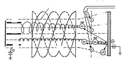
A principal layout of the plasma isotope separation is shown in Fig. 9.
Isotope |
|
Isotope separation |
|
Microwave ion |
||||||||||||||
collectors |
|
area |
|
|
|
source |
||||||||||||
|
|
|
|
|
|
|
|
|
|
|
|
|
|
|
|
|
|
|
|
|
|
|
|
|
|
|
|
|
|
|
|
|
|
|
|
|
|
|
|
|
|
|
|
|
|
|
|
|
3 |
|
|
|
|
|
||
|
|
|
|
|
|
|
|
|
|
|
|
|
|
|
|
|
|
|
|
2 |
|
|
|
|
|
|
|
|
|
|
|
|
|
|
|
|
|
|
|
|
|
|
|
|
|
|
|
|
3 |
|
|
|
|
|
||
|
|
|
|
|
|
|
|
|
|
|
|
|
|
|
4 |
|
||
|
|
|
|
|
|
|
|
|
|
|
|
|
|
|
||||
|
1 |
|
|
|
|
|
|
|
||||||||||
|
|
|
|
|
|
|
|
|
|
|
3 |
|
|
|
|
|||
|
|
|
|
|
|
|
|
|
|
|
|
|
|
|
|
|||
|
|
|
|
|
|
|
|
|
|
|
|
|
|
|
|
|
|
|
|
2 |
|
|
|
|
|
|
|
|
|
|
|
|
|
|
|
|
|
|
|
|
|
|
|
|
|
|
|
|
|
|
|
|
|
|||
|
7 |
|
|
|
|
|
|
|
|
|
|
|
|
|
||||
|
|
|
|
|
|
|
|
5 |
|
|
|
|
|
|||||
|
|
|
|
|
6 |
|
|
|
|
|
|
|
|
|||||
|
|
|
|
|
|
|
|
|
|
|||||||||
|
|
|
|
|
|
|
|
|
|
|
|
|
||||||
|
|
|
|
|
|
|
|
|
|
|
|
|
|
|
|
|
|
|
Fig. 9. Layout of the plasma isotope separation
1 – collectors of the waste; 2 – collectors of the product; 3 – force lines; 4 – metal plate (source of neutral particles); 5 – electrical heati ng area; 6 – antenna of the alternating electrical field; 7 – charging of the collectors to enhance isotope separation efficiency.
If the alternating electrical field with the frequency equaled to the ICF value of 235U ions, for instance, is applied to the flow of spirally rotating ions, then energy of the alternating electrical field can be absorbed by 235U ions only. Just this is the effect of ion cyclotron resonance. Selective increasing the energy of 235U ions can extend their
spiral trajectories and, thus, create the opportunity for spatial separation of 235U and 238U ions. The ICF values of two main uranium isotopes
differ from each other on about 1,2%. The difference can allow it to arrange selective acquisition of 235U and 238U ions on the properly placed and charged collectors.
78
Uranium enrichment technologies
from the standpoint of nuclear non-proliferation
1.Gas diffusion technology
a.Technical complicacy of the GD-technology.
b.Low value of the single-stage enrichment gain (ε´ = 0,0043).
c.High energy consumption (2300-2600 kWh/SWU). Three American GD-plants with total annual throughput of 24 million SWU consume about 7 GWe. Roughly the same energy quantity is consumed by a town with population of 3-4 million people.
So, it is quite improbable to build up and operate a GD-plant covertly.
2.Gas centrifuge technology
a.Technical complicacy of the GC-technology.
b.High values of the single-stage enrichment gain (ε´ = 0,2-0,3).
c.Low values of the specific energy consumption (100-300 kWh/SWU).
So, the GC-technology is dangerous for nuclear non-proliferation regime.
3.The separation-nozzle technology
a.The technology is technically simpler as compared with the GDand GC-processes.
b.The single-stage enrichment gain (ε´ = 0,025) is higher than that of the GD-technology.
c.The specific energy consumption (~3000 kWh/SWU) is higher than that of the GD-technology (2300-2600 kWh/SWU) and, moreover, of the GC-technology (100-300 kWh/SWU).
So, the separation-nozzle technology is less dangerous for nuclear non-proliferation regime than the GC-technology is.
4.Laser technologies
a.Laser isotope separation is a high-efficient technology both on the
values of the single-stage enrichment gain (ε′ = 3-15) and the specific energy consumption (10-50 kWh/SWU).
b. Laser isotope separation is the most sophisticated and sciencecapacious technology.
79
The laser isotope separation technologies are under intense development, testing and perfection now. They are the most promising uranium enrichment technologies and, therefore, the most dangerous ones for nuclear non-proliferation regime.
Control questions
1.Write the material balance relationships for isotope uranium enrichment.
2.What are the basic ideological propositions for determination of the separative work scope and for determination of the separation potential function?
3.Call properties of uranium hexafluoride which are the most important for isotope uranium enrichment.
4.What technologies are used to convert uranium oxides into uranium hexafluoride?
5.What is the gas diffusion technology of isotope uranium enrichment based on?
6.What is the gas centrifuge technology of isotope uranium enrichment based on?
7.What is the separation-nozzle technology of isotope uranium enrichment based on?
8.Call main stages of the atomic vapor laser isotope separation process.
9.Call main stages of the molecular laser isotope separation process.
10.How can the chemical methods of isotope separation be used?
11.What is the plasma technology of isotope separation based on?
80