

Апсе Нуцлеар Течнологиес 2014
.pdfTreatment of high-level wastes (HLW)
There are the following two main forms of HLW:
1. HLW from radiochemical SNF reprocessing facilities.
These wastes are mainly liquid RAW because the industrial-scale SNF reprocessing is primarily based on the aqueous solvent-extraction PUREX-like technologies. As is known, the solvent-extraction reprocessing of SNF discharged from nuclear power reactors can produce about 45 m3 of liquid HLW, 150 m3 of liquid middle-level wastes (MLW) and up to 2000 m3 of liquid low-level wastes (LLW) per one ton of spent fuel.
2. Spent fuel assemblies discharged from nuclear power reactors.
In the USA, where the moratorium has been decreed on radiochemical reprocessing of spent fuel from commercial NPP, these assemblies are considered as a form of the transport RAW containers completely ready for interim storage and, further, for ultimate disposal in deep underground geological repositories.
Main stages of the HLW treatment
1.Interim storage:
a.Spent fuel assemblies are placed into the water storage pools at NPP or at SNF reprocessing plants.
b.Liquid HLW are poured into the steel storage tanks. The storage tanks are put under strict control of heat generation rate (if necessary, forced heat removal must be provided) and elemental composition of the gas cushion over the HLW level (if necessary, air blowing-through is carried out to remove explosive hydrogen produced by water radiolysis).
2.Evaporation of liquid HLW.
The HLW evaporation process provides 200-fold reduction of the HLW volume. However, the following negative effects arise:
a.Specific radioactivity of the evaporated HLW increases.
b.Specific heat generation rate of the evaporated HLW increases too. The larger heat generation rate warms up the evaporated HLW.
c.Corrosion activity of the evaporated HLW intensifies due to the higher corrodent concentrations and to the elevated temperature.
d.Gas release intensifies too due to the radiolysis of water and some liquid HLW components.
131
The following countermeasures are usually undertaken:
a.Control of explosive hydrogen content in the gas cushion above the HLW level in the storage tanks.
b.Periodical air blowing-through for dilution and removal of explosive hydrogen.
c.Control of the gas cushion temperature (< 600С).
d.Forced heat removal.
e.Application of corrosion-resistant alloys and stainless steels as structural materials of the HLW evaporation facilities and the HLW storage tanks.
f.Introduction of the corrosion inhibitors into the evaporated HLW.
g.Disposition of the HLW storage tanks below the earth level on the concrete saucers.
3. Solidification of the evaporated HLW.
Main mission of the HLW solidification is to implant the HLW into a stable inert material (matrix) that can reliably prevent the HLW release into the environment and, finally, into the food chains. Migration ability of the HLW must be substantially weakened, or a reliable HLW immobilization must be guaranteed.
At present, the HLW implantation into some glass compositions, or the HLW vitrification, is considered as the most suitable form for the HLW immobilization.
The following two technologies of the HLW vitrification are the most well-known:
1. One-step technology.
The liquid concentrated HLW are poured into a refractory crucible together with the glass-producing additives. Under gradual warming up, the mixture undergoes the following changes:
a.Ultimate HLW evaporation.
b.Calcination of dried HLW at 300-4000С.
c.Glass-mass melting at 1100-11500С.
After relatively short cooldown, the crucible with all its content is transported to the ultimate disposal site.
2.Two-step technology.
The French AVM-process can be considered as a typical example of the two-step HLW vitrification technologies.
Main stages of the AVM-process:
a. Calcination of the evaporated HLW at 300-4000С.
132
b.Mixing the calcination product with the glass-producing additives.
c.The mixture is poured into a melting furnace.
d.Gradual warming up and formation of the glass-mass at 1100-11500С.
e.Periodical drainage of the glass-mass into steel containers.
f.Interim storage and ultimate disposal of the HLW containers.
Some alternative versions of the HLW vitrification technologies have been developed till now. The alternative technologies presume the HLW implantation into other stable materials, such as ceramics, glassceramics or mineral-like SYNROC materials. The term SYNROC is an abbreviated form from the words “Synthetic Rocks”, i.e. artificial but natural rock-like materials. Development of the SYNROC materials and the technology for the HLW implantation into them (the SYNROC technology) is based on the hope that the SYNROC materials could be characterized by the same physical and chemical properties (primarily, high long-term stability) as their natural analogues.
The SYNROC technology includes the following main stages:
1.Mixing the evaporated HLW with predecessors of the SYNROC materials. These predecessors are, as a rule, various refractory oxides. One typical example of the SYNRIC predecessor composition is as follows: TiO2(71%), CaO(11%), ZrO2(7%), BaO(6%), Al2O3(5%).
2.Calcination of the mixture at 650-7500С.
3.Hot pressing of the mixed powder into the SYNROC pellets (temperature - 1100-12000С, pressure - 150-200 atmospheres).
4.Filling up the steel containers with the SYNROC pellets, interim storage and ultimate disposal of the HLW containers.
Multiple tests were carried out with the HLW-containing SYNROC materials, and the following main results were obtained:
1.Physical, chemical and corrosion-resistance properties of the SYNROC materials appeared to be very similar with those of natural rock minerals, i.e. the SYNROC materials are able to maintain their stability under any environmental impacts for sufficiently long time periods.
2.The SYNROC materials can retain up to 20% HLW.
3.The water-leaching rate of the SYNROC materials covered the range of 10-6÷10 -5 gram from 1 cm2 of the sample surface a day (g/cm2·day). The achievable HLW contents and the HLW leaching rates of the SYNROC materials are inferior to analogous properties of the borosilicate glass. The borosilicate glasses can retain up to 30% HLW.
133
In general, the glasses are characterized by intrinsically disordered molecular lattice and, therefore, the glasses are able to keep wide spectrum of various radioisotopes. The SYNROC materials with their finely ordered crystalline lattice are able to keep only the radioisotope compounds with certain atomic dimensions and with certain valencies. The water-leaching rate of the vitrified HLW is evaluated as 10-8÷10 -7 g/cm2·day.
So, the SYNROC materials are inferior only to the glasses in respect to the achievable HLW content and the water-leaching rate but, nevertheless, they remain to be the second candidate for the HLW immobilization.
After the HLW are immobilized in the glass-mass or in the SYNROC pellets, these solidified HLW forms are placed into the steel containers. The further HLW management foresees sufficiently long (up to 50 years) interim storage in the near-to-surface storage points with air or water cooling. The containers can be periodically retrieved to investigate the current state of the solidified HLW and, if necessary, to perform their additional treatment.
The next stage is an ultimate disposal of the HLW containers in deep underground geological repositories. Geological formation can be regarded as a suitable place for ultimate disposal of the HLW containers only if the formation satisfies the following requirements:
1.Geographical properties of the formation:
a.Far distance from the densely populated areas.
b.Low seismicity and low probability of earthquakes.
c.Far distance from the level of ground waters.
d.The geological stratum must not enter the earth surface.
2.Physical properties of the formation:
a.Good heat conductivity and heat capacity.
b.Good mechanical strength and plasticity.
c.Good chemical stability and retentivity of radioisotopes.
The following three geological formations are being evaluated now as the most promising candidates for ultimate disposal of the HLW containers in deep underground repositories:
1.Salt mines.
2.Sedimentary clayish formations.
3.Rocky formations.
134
Unfortunately, it appeared impossible to distinguish one the most suitable geological formation from these candidatures even basing only on their physical properties. All the candidates are characterized by their own advantages and drawbacks.
Salt mines
Advantages:
1.Far distance from ground waters, i.e. hydrological conditions of the salt mines were so stable that the salts remained in their initial state for a geological-scale time period (some millions or even milliards of years) despite of their good solubility by light water.
2.Good plasticity.
3.High heat conductivity.
Drawbacks:
1.Good solubility by light water.
2.Potential usefulness for many industrial branches.
3.Radiolysis by ionizing radiations with intense release of harmful gaseous substance (chlorine, for instance).
Sedimentary clayish formations
Advantages:
1.Full water impermeability.
2. High retentivity of radioactive fission products (with the exception of 129I and 99Tc).
3. Good plasticity.
Drawbacks:
1.Low retentivity of 129I and 99Tc, radioisotopes with high migration ability.
2.Low heat conductivity.
3.Proximity to the earth surface.
Rocky formations
Advantages:
1.High water impermeability.
2.Good mechanical strength and chemical stability.
Drawbacks:
1.Low plasticity, i.e. high probability for the cracks to appear as potential pathways for the HLW migration into the biosphere.
2.Low heat conductivity.
The most advanced all over the world project of the deep underground HLW repository is the Yucca Mountain project (Nevada,
135
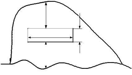
USA). Schematic layout of the Yucca Mountain repository is shown in Fig. 15.
300 мm |
м |
|
7.6 |
7900 мm |
|
|
7.6 m |
|
200 мm |
|
||
|
|
|
|
|
|
|
|
LevelУровеньof groundгрунтовыхwaterвод
Fig. 15. Layout of the Yucca Mountain repository level of ground water
Construction of the Yucca Mountain repository was begun in 1994. By April 1997 the main drifting works were finished with the following dimensions of the major tunnel: length – 7900 m; he ight – 7,6 m; distance from the level of ground water – 200 m dow nwards; distance from the mountain top – 300 m upwards. About $20 mi lliards were already spent for these drifting works. In 2002 all the studies on geological, hydrological, geochemical and geothermal properties of the repository site were completed, and the US Nuclear Regulatory Commission received the application on start-up of the repository operation. As was previously planned, the loading process of the repository with the HLW containers must be begun in 2010 (total capacity of the Yucca Mountain repository was evaluated as 70,000 t HLW). However, the license on the repository operation was not issued by the NRC till now. Moreover, federal funding of the Yucca Mountain project was ended just in 2010.
The geological formation of the Yucca Mountain repository is a rocky tuff with large quantity of cracks. Vertical infiltration of light
136
water from upwards into the major tunnel was measured and appeared equal to approximately one liter per one square meter of the tunnel bottom annually, i.e. 1 mm-thick water layer a year.
Some numerical evaluations demonstrated that major effect on potential contacts of ground water with radioisotopes and probability of their release into the biosphere from the fully loaded HLW repository Yucca Mountain is mainly defined by residual heat generation. The mountain part adjacent to the major tunnel can be warmed up to 1300С, i.e. above boiling temperature of ground water. So intense warming up can create the closed circuit of natural water convection from hot HLW repository to relatively cold rocks. There, water vapor condenses and flows down. That is why hydrological conditions of fully loaded repository cardinally differ from those in empty repository.
The following changes can occur in hydrological conditions of the fully loaded HLW repository:
1.Formation of the condensed water layer above the HLW repository by natural convection of hot vapor and cold water.
2.The rocky area adjacent to the HLW repository is impregnated with water.
3.Intense cracking of the tuff layers adjacent to the HLW repository by hot vapor and temperature gradient.
4.Chemical activity oh hot water enhances. Consequently, corrosion rate of the HLW containers and solubility of radioisotopes can increase.
Central zone of the HLW repository can remain relatively dry because of maximal heat generation rate and rapid evaporation of the flowing down water. Atmosphere in peripheral zone of the HLW repository can be more humid and, thus, it can intensify corrosion of the HLW containers. So, internal heat generation can be a serous capacitylimiting factor for the very expensive HLW repositories. The heat
generation is mainly caused by radioactive decays of some long-lived fission products (137Cs, 90Sr) and minor actinides (radioisotopes of neptunium, americium and curium). In a relatively short-term perspective (100-200 years), fission products are main contributors into the internal heat generation. In a longer perspective (t > 1000 years) the dominant role in the decay heat generation passes from fission products to minor actinides.
Therefore, some advanced alternative approaches to the HLW management are under thorough studies now throughout the world.
137
These approaches presume various options for extraction and partitioning of long-lived fission products (LLFP) and minor actinides. The separated radioisotopes can be further used as heat sources and sources of ionizing radiation in many industrial branches.
Minor actinides are able to enhance nuclear non-proliferation regime because neutron irradiation of 237Np and 241Am in nuclear reactors can transform them into plutonium isotope 238Pu, intense source of decay heat and spontaneous fission neutrons. Plutonium with high enough content of 238Pu becomes completely unsuitable for manufacturing of any nuclear explosive devices.
Some other approaches presume neutron transmutation of LLFP and minor actinides in the dedicated irradiation facilities (nuclear reactors, accelerator-driven systems, thermonuclear installations) where the most harmful radioisotopes can be converted into short-lived or stable nuclides.
Treatment of liquid middle-level and low-level radiowastes (MLW and LLW)
The following procedures are used to treat liquid MLW and LLW:
1.Precipitation and removal of solid particles from the MLW and LLW solutions.
2.Ion-exchange purification of the clarified solutions.
3.Evaporation up to the dry sediment.
4.Immobilization by bituminization or cementation.
5.Placement of the solidified radiowastes into the steel containers.
6.Interim storage and ultimate disposal of the steel containers.
Bitumen as a material for RAW immobilization can offer the following advantages:
1.Low leaching rate by light water.
2.Suitability for immobilization of any chemical RAW forms (salts, hydroxides, organics).
3.Good radiation resistance.
However, bitumen is an inflammable material as a by-product of natural oil reprocessing, and bitumen softens under warming up.
The alternative option to the RAW bituminization is a cementation process, i.e. RAW implantation into the concrete blocks.
138
Concrete a material for RAW immobilization can offer the following advantages:
1.Low cost and simplicity of the cementation process.
2.Good radiation resistance.
3.High heat conductivity.
4.Concrete is not an inflammable material and does not soften when warmed up.
Unfortunately, concrete is very sensitive to the water leaching. Comparative data on the water leaching rates of the most widely known materials for RAW immobilization are presented below:
1. |
Glass: |
10-8 ¸ 10-7 |
g/cm2×day; |
2. SYNROC: |
10-6 ¸ 10-5 |
g/cm2×day; |
|
3. |
Bitumen: |
10-6 ¸ 10-4 |
g/cm2×day; |
4. |
Concrete: |
10-3 ¸ 10-2 |
g/cm2×day. |
That is why glasses and the SYNROC materials are preferentially used to immobilize HLW while bitumen and concrete – for immobilization of MLW and LLW.
Chemical stability of the concrete blocks can be enhanced by impregnating the cement mixture with some organic monomers. At solidification, the monomers are polymerized, and chemical stability of the concrete blocks improves substantially.
Treatment of gaseous RAW
Gaseous RAW can produce the following negative effects on human organism:
1.Direct external irradiation and irradiation by the fallen out radioactive particles.
2.Internal irradiation at inhalation of air contaminated with gaseous RAW.
3.Chemical toxicity of gaseous RAW at inhalation.
The following radioisotopes are main components of gaseous RAW:
1.Radioactive noble gases (radioisotopes of krypton and xenon).
2.Iodine radioisotopes.
3.Carbon radioisotope 14С.
4.Tritium.
139
After lengthy (5-10 years) staying in the SNF storage pool at NPP only the following relatively long-lived gaseous radioisotopes remained in RAW composition:
1.Of noble gases – only 85Kr (half-live T1/2 = 10,7 years).
2.Of iodine radioisotopes – only 129I (T1/2 = 1,6×10⁷ years).
3.Radiocarbon 14С (T1/2 = 5730 years).
4.Tritium 3H (T1/2 = 12,3 years).
Removal of 85Kr. The following methods are used to remove 85Kr from gaseous RAW composition:
1.Cryogenic adsorption by activated charcoal or molecular sieves as ultra-filters.
2.Cryogenic adsorption by liquid carbon dioxide or liquid
fluorocarbons.
Removal of 129I. In gaseous RAW composition the radioiodine can
be in the forms of molecular iodine I2, iodides (I-) and iodates (IO3-). The following methods are used to remove 129I from gaseous RAW composition:
1.Absorption of the radioiodine by alkaline or acidic solutions in scrubbers where the radioiodine is oxidized up to solid insoluble compound HI2O8.
2.Chemisorption of the radioiodine onto the zeolite impregnated with silver nitrate AgNO3. Molecular radioiodine is bound into insoluble silver iodide and silver iodate through the following chemical reaction:
2 AgNO3+ I2 + H2O + O2 ® AgI +AgIO3 + 2 HNO3 .
Removal of 14C. Gaseous RAW contains radiocarbon 14C in its oxide forms 14CO and 14CO2. Radiocarbon is a product of neutron 14N(n,p)14C reaction with nitrogen that is contained in air, in coolant and structural materials as an impurity.
Unfortunately, till now no any industrial-scale technologies have been developed to catch 14CO or 14CO2 efficiently. In laboratorial studies some fluorocarbons demonstrated highly efficient absorption of 14C (up to 99,9% 14C) within low temperature range from -400С to +40С.
Removal of tritium. In nuclear reactors tritium can be produced by neutron reactions with coolant and some impurities (hydrogen, lithium) in structural materials, In addition, tritium is a product of very rare ternary fission reactions with emission of three (not usual two) fission
140