

Апсе Нуцлеар Течнологиес 2014
.pdf1.Reliable radiation protection of the staff involved, population and the environment against neutron and gamma-emissions (metal vessel containing high-efficiency neutron moderators and neutron absorbers).
2.Reliable nuclear safety ensuring (metal shelves containing strong neutron absorbers, limitations on the number of spent fuel assemblies to be loaded into the transport casks).
3.Reliable removal of decay heat (the finned outer surface, forced circulation of coolant in the inner cavity of the transport cask).
4.Reliable hermetization of the transport casks even under severe accidental conditions.
To check up hermeticity of the transport casks, they must undergo the following severe tests:
a. Drop test from 9-m height onto a steel plate.
b. Puncture test from 1-m height onto a vertical metal rod (15 cm in diameter).
c. Immersion test in light water (depth - 15 m, duration – 8 hours).
d. Fire test – staying in flame at 800 0С for 30 minutes plus 2-hour staying without a forced cooldown.
The IAEA has elaborated the following requirements to thermal
parameters of the transport casks in operation:
a. Temperature of the cask surface must be below 820С at the ambient air temperature of 380С.
b. Internal coolant pressure in the cask cavity must be below 7 atmospheres.
c. The outer surface of the cask must be extended by fins. Additional 30 m2 of the heat removal area would be large enough for safe shipment
of spent fuel assemblies with total power from 25 to 30 kW ( 30 spent fuel assemblies from VVER-440 after 3-year cooling period) without a forced cooldown.
Some technical specifications of typical transport casks currently in usage for transportation of spent LWR fuel assemblies are presented in Table 10.
101
|
|
|
|
|
|
|
Таблица 10 |
|
|
|
Transport casks for spent LWR fuel assemblies |
|
|||||
|
|
|
|
|
|
|
|
|
Reactor |
Form |
Mass, |
Diameter, |
Material |
Fuel mass, |
Number |
Coolant |
|
t |
length, m |
t |
of FA |
|||||
VVER- |
Vertical |
90 |
2,3 |
Steel, |
3,8 |
30 |
Water, |
|
440 |
cylinder |
4,4 |
40 cm |
helium |
||||
|
|
|
||||||
VVER- |
Horizontal |
110 |
2,1 |
Steel, |
3,0 |
|
Water |
|
1000 |
cylinder |
41 cm |
6 |
|||||
|
6,1 |
|
|
|||||
|
|
|
|
|
|
|
||
PWR |
-”- |
70 |
1,5 |
Steel |
4,0 |
7(PWR) |
Water |
|
BWR |
5,4 |
18(BWR) |
||||||
|
|
|
|
|
||||
Control questions
1.Describe briefly a typical transport cask for spent fuel assemblies.
2.What requirements must the transport cask design satisfy?
3.What tests must a typical transport cask undergo?
102
CHAPTER 8. TECHNOLOGIES FOR REPROCESSING OF SPENT NUCLEAR FUEL
The following aims are pursued by technologies intended for spent nuclear fuel (SNF) reprocessing:
1.Recovery of accumulated plutonium and residual uranium for the repeated use (recycle) as fissile and fertile materials.
2.Separation of fission products and transuranium elements for further treatment as radioactive wastes.
The IAEA has worked out the following recommendations on the reprocessing quality of spent fuel assemblies discharged from power LWR after the standard operation cycle (fuel burn-up - 33 GWd/t, the cooling time – 10 years):
1.Extent of plutonium and uranium recovery – above 9 9,9%.
2.Decontamination factors, i.e. ratios of an impurity content
before treatment to an impurity content after treatment: a. Uranium from plutonium – at the level of 10 7.
b. Uranium from fission products – at the level of 107. c. Plutonium from uranium – at the level of 10 6.
d. Plutonium from fission products – at the kevel o f 108.
Such a fine purification gave a foundation to call this approach as the
“clean fuel – dirty waste” concept. The concept is very attractive for NFC closure but it can produce some difficulties for nuclear nonproliferation regime. Therefore, when some advanced SNF reprocessing technologies have been developed, which deliberately left some remarkable quantity of radioactive fission products in the recycled fuel to enhance nuclear non-proliferation regime, a new approach arose, namely the “dirty fuel – clean waste” concept.
Nearly 7000 t SNF are discharged annually from the world NPP. Capabilities of the existing and under construction facilities for SNF reprocessing are shown in Table 11. As is seen, the existing SNF reprocessing plants are not able to deal with full annual SNF amount discharged from all NPP in operation throughout the world.
SNF reprocessing plant is a rather expensive enterprise. Approximate specific cost of SNF reprocessing is evaluated as 500 US dollars/kg SNF.
103

Table 11
|
Capabilities of SNF reprocessing plants |
|
|
|
|
Country |
|
Annual throughput, t SNF |
Great Britain |
|
1500 |
|
1200 |
|
|
|
|
|
|
|
France |
|
900 |
|
800 |
|
|
|
|
Russia |
|
400 |
India |
|
2 × 100 |
Japan |
|
90 |
China |
|
50 |
|
|
Under construction |
Russia |
1500 |
|
Japan |
800 |
|
Total: 5100 t/year in operation, 2300 t/year under construction.
Classification of SNF reprocessing technologies
1.Aqueous (wet) reprocessing technologies:
a.Solvent-extraction processes which are based on selective recovery of uranium and plutonium compounds from fuel-containing solutions by organic extractants.
b.Precipitation processes which are based on the formation of insoluble uranium and plutonium compounds with their further deposition on a vessel bottom by introducing appropriate precipitants.
2.Non-aqueous (dry) technologies:
a.Pyrochemical processes: for example, the fluoride volatility process that is based on different volatility and sorption of uranium, plutonium and FP fluorides.
b.Pyrometallurgical processes: for example, the electrochemical refinement process that is based on different transport properties of uranium, plutonium and fission products in molten salts.
The most widely used and industrially matured technologies are the aqueous solvent-extraction processes. The PUREX (Plutonium and Uranium Recovery by Extraction) technology is the most representative example of these processes.
104
Main stages of the PUREX-process
1.Dismantling of spent fuel assemblies and chopping of spent fuel rods.
2.Preliminary oxidation (voloxidation) of spent fuel.
3.Dissolution of spent fuel and preparation of the fuel solution for uranium and plutonium extraction.
4.The extraction – re-extraction cycles.
These stages of the PUREX-process are described in more details below.
Dismantling of fuel assemblies and chopping of fuel rods. Thus, spent UOX-fuel assemblies, after lengthy cooldown period, were shipped to radiochemical plant for reprocessing. At first, the following initial procedures must be carried out with spent fuel assemblies:
1.Removal of end caps, wrappers and spacers, dismantling of fuel lattices.
2.Shearing operation that chops long fuel rods into short (2,5-5 cm) pieces.
Dismantling of fuel assemblies and chopping of fuel rods must be done in the closed hot cells with inert atmosphere (nitrogen or argon).
Preliminary SNF oxidation (voloxidation). The next stage of the PUREX-process consists in preliminary oxidation of spent fuel pieces
by oxygen as elevated temperatures ( 6000С). Uranium dioxide UO2 converts into uranium octa-oxide U3O8:
3 UO2 + O2 → U3O8.
The UO2–to-U 3O8 conversion leads to the following positive effects:
a.Fuel density decreases on 30% due to so different densities of initial and final reagents: γ(UO2) ≈ 11 g/cm3, γ(U3O8) ≈ 8,3 g/cm3. As consequences, fuel volume increases according to this difference, fuel meat becomes more porous and friable than can facilitate the further dissolution of fuel pieces.
b.Fuel crystalline lattice undergoes substantial changes.
c.Both these effects create the favorite conditions for intense release of tritium, gaseous and volatile fission products. If the voloxidation
temperature is kept at 6500С for 12 hours, then up to 99,96% tritium, 70% 85Kr, 40% 129I and 90% 106Ru can escape the fuel pieces.
105
Dissolution of fuel pieces. Spent UOX-fuel pieces are dissolved by boiling (t 1000C) nitric acid HNO3 concentrated up to 6-12 М for 4-6 hours:
UO2 + HNO3 → UO2 (NO3)2 + NOX + H2O.
Simultaneously, nitric acid can be recombinated in the dissolver where air or oxygen flow is pumped to intensify the regeneration process:
NOX + H2O+ O2 → HNO3.
The use of nitrogen oxides for nitric acid regeneration promotes forming a smoke-free process, i.e. without any release of gaseous nitrogen oxides into the environment.
In the process of SNF dissolving, metal claddings (zirconium-based alloys or stainless steels) of fuel rods remain non-dissolved and can be easily removed for further treatment as solid radioactive wastes.
Preparation of SNF solution to the extraction – reextraction process consists of the following steps:
1.Clarification of SNF solution:
a.Filtration for removal of small ( 3 microns) solid particles through metal-ceramic filters or porous polypropylene with application of some coagulants for enlarging the particles.
b.Centrifugation with application of some coagulants for removal of
the smaller ( 1 micron) solid particles.
2. Removal of some gaseous and volatile fission products from SNF solution:
a. Barbotage of SNF solution by air flow for removal of radioactive iodine ions I- and IO3-. Then, the Barbotage off-gases are pumped through the filters impregnated with silver nitrate AgNO3:
3 I2 + 6 AgNO3 + 3 H2O → 5 AgI + AgIO3 + 6 HNO3.
b. Barbotage of SNF solution by ozone flow for removal of radioactive ruthenium ions Ru4+:
Ru4+ + 2 O3 + 2 H2O → RuO4 + 2 O2 + 2 H2.
106
Ruthenium oxide RuO4 is then removed from the barbotage off-gases by reaction with sodium hydroxide NaOH.
c. Removal of inert gases (Kr, Xe) by the barbotage process with further their sorption in zeolite or activated charcoal at reduced temperatures. Then, the barbotage off-gases are diluted with air flow down to the acceptable concentrations and released into the environment.
3. Correction of SNF solution acidity by water dilution or evaporation to reach the level of 2-4 М HNO3.
Extraction. The solvent-extraction technology of SNF reprocessing is very similar to the extraction affinage technology which was applied at the NFC front-end for removal of neutron-absorbing impurities from natural uranium concentrate. The extraction affinage process presumes dissolving uranium concentrate U3O8 by nitric acid, recovery of uranylnitrate UO2(NO3)2 by organic extractant tri-butyl-phosphate (TBP), reextraction of uranyl-nitrate from organic fraction by hydrogen peroxide H2O2 or ammonium bicarbonate NH4HCO3 and precipitation of insoluble uranium compounds.
The following significant distinctions can be seen between the extraction affinage of natural uranium concentrate and the solventextraction reprocessing of spent UOX-fuel:
1.Acidic SNF solution contains residual amount of enriched uranium, reactor-grade plutonium, fission products and minor actinides where FP and MA play a very similar role that was played by neutronabsorbing impurities in the extraction affinage process, i.e. they must be removed.
2.The extraction affinage process dealt with weakly radioactive materials (natural uranium and impurities) while the solvent-extraction SNF reprocessing technology deals with FP and MA, intense radiation and heat sources.
The solvent extraction process, like the extraction affinage, applies the same organic extractant TBP in mixture with an inert organic
dilutant for reduction of TBP viscosity. Density of the “TBP-dilutant” mixture covers the range of 0,8-0,9 g/cm3 while density of acidic SNF solution covers the slightly heavier range of 1,1-1,2 g/cm3.
Thus, the solvent-extraction process is a separation of uranyl-nitrate between two immiscible fractions, namely the light organic fraction
107
(TBP plus dilutant) and the heavy aqueous fraction (acidic SNF solution).
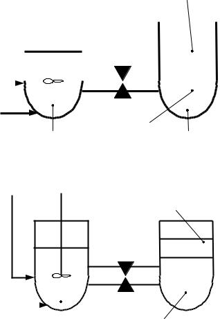
Layout of the extraction – re-extraction process. The extraction process takes place in two connected vessels, mixer and settler. Acidic SNF solution and extractant TBP are pumped into the mixer. Their intense mixing leads to tight SNF-TBP contacts, uranyl and plutonyl nitrates receive an opportunity to form stable solvates with TBP molecules. Then, plutonium and uranium accumulate in the light organic fraction while fission products and minor actinides accumulate in the heavy aqueous fraction. Afterwards, the mixture is pumped into the settler where the light organic fraction (extract) and the heavy aqueous fraction (raffinate) can be easily separated. The extraction process is over.
The-re-extraction process takes place also in two connected vessels, mixer and settler. The extract and the aqueous washing solution are pumped into the mixer. Their intense mixing leads to the uranium and plutonium compounds are washed off the extract. Then, the mixture is pumped into the settler where the light organic fraction (extractant) and the heavy aqueous fraction (re-extract) can be easily separated. The extractant can be used again in the extraction process, after purification and regeneration procedures. The re-extraction process is over.
Thus, uranium and plutonium compounds are partially separated from fission products and minor actinides. Multiple application of the extraction – re-extraction process can separate the m completely. General layout of the extraction – re-extraction process is shown in Fig. 10.
108
Extractant |
|
|
Light organic fraction |
|||
TBP |
|
|
(extract) |
|||
|
|
|
|
|
|
|
|
|
|
|
|
|
|
|
|
|
|
|
|
|
|
|
|
|
|
|
|
|
|
|
|
|
|
|
|
|
|
|
|
|
|
|
|
|
|
|
|
|
|
|
Heavy |
SNF |
|
fraction |
solution |
Mixer |
(raffinate) |
|
Settler |
|
|
|
|
Organic fraction |
|
Return to the extraction |
|
|
Extractant
|
|
|
|
|
|
Aqueous |
|
|
Aqueous |
||
washing |
|
Mixer |
|||
|
|||||
|
fraction |
||||
solution |
|
||||
|
|
(re-extract) |
|||
|
|
|
|
|
|
Fig. 10. The extraction – re-extraction process
109

The coefficient D (Distribution Ratio) characterizes distribution of elemental concentrations C between the light organic fraction and the heavy aqueous fraction:
D = Celement (organic fraction) .
Celement (aqueous fraction)
Evidently, if the distribution ratio of a certain element D > 1, then this element concentrates in the light organic fraction, and, vice versa, if D < 1, then the element concentrates in the heavy aqueous fraction.
The well-known quadratic dependencies of the distribution ratios on the SNF solution acidity are shown in Fig. 11 for uranium (a typical representative of fuel materials) and for zirconium (a typical representative of fission products).
|
100 |
D |
|
|
|
|
|
|
|
|
|
|
|
|
|
|
10 |
|
|
|
|
Uranium |
|
ratio |
|
|
|
|
|
|
|
|
|
|
|
|
|
FP |
|
Distribution |
|
|
|
|
|
|
|
1 |
|
|
|
|
|
|
|
0.1 |
|
|
|
|
|
|
|
|
|
|
|
|
|
|
|
|
|
|
|
|
|
C HNO , m |
|
|
0.01 |
|
|
|
|
|
3 |
|
1 |
2 |
3 |
4 |
5 |
6 |
|
|
0 |
||||||
SNF solution acidity
Fig. 11. Dependencies of the distribution ratios
on the SNF solution acidity
110