


|
System Description |
|
Wireless Power Transfer |
Power Transmitter Designs |
Version 1.1 Addendum A11 |
2.1.1.2Electrical details
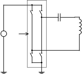
As shown in Figure 2-4, Power Transmitter design A11 uses a full-bridge inverter to drive the Primary Coil and a series capacitance. Within the Operating Frequency range specified below, the assembly of
Primary Coil, Shielding, and magnet has a self inductance |
μH. |
The value of the series |
|
capacitance is |
μF. The input voltage to the full-bridge inverter is |
V. (Informative) Near |
|
resonance, the voltage developed across the series capacitance can reach levels exceeding 100 V pk-pk.
Power Transmitter design A11 uses the Operating Frequency and duty cycle of the Power Signal in order to control the amount of power that is transferred. For this purpose, the Operating Frequency range of the full-bridge inverter is kHz with a duty cycle of 50%; and its duty cycle range is 10…50%
at an Operating Frequency of 205 kHz. A higher Operating Frequency or lower duty cycle result in the transfer of a lower amount of power. In order to achieve a sufficiently accurate adjustment of the amount of power that is transferred, a type A5 Power Transmitter shall control the Operating Frequency with a resolution of
|
kHz, |
for fop in the 110…175 kHz range; |
|
kHz, |
for fop in the 175…205 kHz range; |
or better. In addition, a type A5 Power Transmitter shall control the duty cycle of the Power Signal with a resolution of 0.1% or better.
When a type A11 Power Transmitter first applies a Power Signal (Digital Ping; see Section 5.2.1), it shall use an initial Operating Frequency of 175 kHz (and a duty cycle of 50%).
Control of the power transfer shall proceed using the PID algorithm, which is defined in [Part 1], Section 5.2.3.1. The controlled variable ( ) introduced in the definition of that algorithm represents the Operating Frequency or the duty cycle. In order to guarantee sufficiently accurate power control, a type A11 Power Transmitter shall determine the amplitude of the Primary Cell current—which is equal to the Primary Coil current—with a resolution of 7 mA or better. Finally, Table 2-2, Table 2-3, and Table 2-4 provide the values of several parameters, which are used in the PID algorithm.
Full-bridge
Inverter
Input
Voltage + Control
‒
CP |
LP |
Figure 2-4: Electrical diagram (outline) of Power Transmitter design A11
8 |
© Wireless Power Consortium, May 2012 |
|
|
|
|
System Description |
|
|
|
|
|
|||||||
|
|
|
Wireless Power Transfer |
|
|
|
|
|
||||||||
Version 1.1 Addendum A11 |
|
|
|
|
|
|
|
|
|
|
Power Transmitter Designs |
|||||
|
|
Table 2-2: PID parameters for Operating Frequency control |
||||||||||||||
|
|
|
|
|
|
|
|
|
|
|
|
|
|
|
|
|
|
|
Parameter |
|
|
|
|
|
Symbol |
|
|
Value |
|
|
Unit |
|
|
|
|
Proportional gain |
|
|
|
|
|
|
|
10 |
|
|
mA-1 |
|
||
|
|
Integral gain |
|
|
|
|
|
|
|
0.05 |
|
|
mA-1ms-1 |
|
||
|
|
Derivative gain |
|
|
|
|
|
|
|
0 |
|
|
mA-1ms |
|
||
|
|
Integral term limit |
|
|
|
|
|
|
|
3,000 |
|
|
N.A. |
|
||
|
|
|
|
|
|
|
|
|
|
|
|
|
|
|
||
|
|
PID output limit |
|
|
|
|
|
|
|
20,000 |
|
|
N.A. |
|
||
|
|
|
|
|
|
|
|
|
|
|||||||
|
|
Table 2-3: Operating Frequency dependent scaling factor |
||||||||||||||
|
|
|
|
|
|
|
|
|
|
|
|
|
|
|||
|
|
Frequency Range [kHz] |
|
|
|
Scaling Factor |
[Hz] |
|
|
|
|
|
||||
|
|
|
|
|
|
|
|
|
|
|
|
|
|
|
|
|
|
|
110…140 |
|
|
|
|
|
|
1.5 |
|
|
|
|
|
||
|
|
|
|
|
|
|
|
|
|
|
|
|
|
|
||
|
|
140…160 |
|
|
|
|
|
|
2 |
|
|
|
|
|
||
|
|
|
|
|
|
|
|
|
|
|
|
|
|
|
||
|
|
160…180 |
|
|
|
|
|
|
3 |
|
|
|
|
|
||
|
|
|
|
|
|
|
|
|
|
|
|
|
|
|
||
|
|
180…205 |
|
|
|
|
|
|
5 |
|
|
|
|
|
||
|
|
|
|
|
|
|
|
|
|
|||||||
|
|
Table 2-4: PID parameters for duty cycle control |
|
|
|
|
|
|||||||||
|
|
|
|
|
|
|
|
|
|
|
|
|
|
|
||
|
|
Parameter |
|
|
|
|
|
Symbol |
|
|
Value |
|
|
Unit |
|
|
|
|
Proportional gain |
|
|
|
|
|
|
|
10 |
|
|
mA-1 |
|
||
|
|
Integral gain |
|
|
|
|
|
|
|
0.05 |
|
|
mA-1ms-1 |
|
||
|
|
Derivative gain |
|
|
|
|
|
|
|
0 |
|
|
mA-1ms |
|
||
|
|
Integral term limit |
|
|
|
|
|
|
|
3,000 |
|
|
N.A. |
|
||
|
|
|
|
|
|
|
|
|
|
|
|
|
|
|
||
|
|
PID output limit |
|
|
|
|
|
|
|
20,000 |
|
|
N.A. |
|
||
|
|
|
|
|
|
|
|
|
|
|
|
|
|
|
|
|
|
|
Scaling factor |
|
|
|
|
|
|
|
|
–0.01 |
|
% |
|
|
|
|
|
|
|
|
|
|
|
|
|
|
|
|
|
|
|
|
© Wireless Power Consortium, May 2012 |
9 |

|
System Description |
|
Wireless Power Transfer |
Power Transmitter Designs |
Version 1.1 Addendum A11 |
This page is intentionally left blank.
10 |
© Wireless Power Consortium, May 2012 |

System Description
Wireless Power Transfer
Volume I: Low Power
Part 1: Interface Definition
Version 1.1 Addendum A12
July 2012

System Description
Wireless Power Transfer
Version 1.1 Addendum A12
System Description
Wireless Power Transfer
Volume I: Low Power
Part 1: Interface Definition
Version 1.1 Addendum A12
July 2012
© Wireless Power Consortium, July 2012

System Description
Wireless Power Transfer
Version 1.1 Addendum A12
COPYRIGHT
This System Description Wireless Power Transfer is published by the Wireless Power Consortium, and has been prepared by the Wireless Power Consortium in close co-operation with the members of the Wireless Power Consortium. All rights are reserved. Reproduction in whole or in part is prohibited without express and prior written permission of the Wireless Power Consortium.
DISCLAIMER
The information contained herein is believed to be accurate as of the date of publication. However, the Wireless Power Consortium will not be liable for any damages, including indirect or consequential, from use of this System Description Wireless Power Transfer or reliance on the accuracy of this document.
NOTICE
For any further explanation of the contents of this document, or in case of any perceived inconsistency or ambiguity of interpretation, or for any information regarding the associated patent license program, please contact: info@wirelesspowerconsortium.com.
© Wireless Power Consortium, July 2012
|
System Description |
|
Wireless Power Transfer |
Version 1.1 Addendum A12 |
Table of Contents |
Table of Contents
1 |
General................................................................................................................... |
1 |
||
|
1.1 |
Scope............................................................................................................................................................................................. |
1 |
|
|
1.2 |
Conformance and references ............................................................................................................................................. |
1 |
|
|
1.3 |
Definitions .................................................................................................................................................................................. |
1 |
|
|
1.4 |
Acronyms .................................................................................................................................................................................... |
1 |
|
|
1.5 |
Symbols........................................................................................................................................................................................ |
1 |
|
|
1.6 |
Conventions ............................................................................................................................................................................... |
2 |
|
|
1.6.1 |
Cross references ............................................................................................................................................................ |
2 |
|
|
1.6.2 |
Informative text............................................................................................................................................................. |
2 |
|
|
1.6.3 |
Terms in capitals........................................................................................................................................................... |
2 |
|
|
1.6.4 |
Notation of numbers.................................................................................................................................................... |
2 |
|
|
1.6.5 Units of physical quantities ...................................................................................................................................... |
2 |
||
|
1.6.6 Bit ordering in a byte................................................................................................................................................... |
2 |
||
|
1.6.7 |
Byte numbering ............................................................................................................................................................. |
2 |
|
|
1.6.8 |
Multiple-bit Fields......................................................................................................................................................... |
2 |
|
|
1.7 |
Operators .................................................................................................................................................................................... |
3 |
|
|
1.7.1 |
Exclusive-OR ................................................................................................................................................................... |
3 |
|
|
1.7.2 |
Concatenation................................................................................................................................................................. |
3 |
|
2 |
Power Transmitter Designs............................................................................ |
5 |
||
|
2.1.1 Power Transmitter design A12............................................................................................................................... |
5 |
||
© Wireless Power Consortium, July 2012 |
i |

System Description |
|
Wireless Power Transfer |
|
Table of Contents |
Version 1.1 Addendum A12 |
List of Figures |
|
Figure 1-1: Bit positions in a byte ..................................................................................................................................................... |
2 |
Figure 1-2: Example of multiple-bit field....................................................................................................................................... |
3 |
Figure 2-1: Functional block diagram of Power Transmitter design A12....................................................................... |
5 |
Figure 2-2: Primary Coil of Power Transmitter design A12.................................................................................................. |
6 |
Figure 2-3: Electrical diagram (outline) of Power Transmitter design A12 .................................................................. |
8 |
ii |
© Wireless Power Consortium, July 2012 |

System Description |
|
Wireless Power Transfer |
|
Version 1.1 Addendum A12 |
Table of Contents |
List of Tables |
|
Table 2-1: Primary Coil parameters of Power Transmitter design A12 |
..........................................................................6 |
Table 2-2: PID parameters for Operating Frequency control............................................................................................... |
9 |
Table 2-3: PID parameters for duty cycle control ...................................................................................................................... |
9 |
© Wireless Power Consortium, July 2012 |
iii |

|
System Description |
|
Wireless Power Transfer |
Table of Contents |
Version 1.1 Addendum A12 |
This page is intentionally left blank.
iv |
© Wireless Power Consortium, July 2012 |
|
System Description |
|
Wireless Power Transfer |
Version 1.1 Addendum A12 |
General |
1 General
1.1Scope
Volume I of the System Description Wireless Power Transfer consists of the following documents:
Part 1, Interface Definition.
Part 2, Performance Requirements.
Part 3, Compliance Testing.
This document defines the addition of a new Power Transmitter design. The material contained in this document will be integrated into Part 1 of Volume I of the System Description Wireless Power Transfer, at some later time.
1.2Conformance and references
All specifications in this document are mandatory, unless specifically indicated as recommended or optional or informative. To avoid any doubt, the word “shall” indicates a mandatory behavior of the specified component, i.e. it is a violation of this System Description Wireless Power Transfer if the specified component does not exhibit the behavior as defined. In addition, the word “should” indicates a recommended behavior of the specified component, i.e. it is not a violation of this System Description Wireless Power Transfer if the specified component has valid reasons to deviate from the defined behavior. And finally, the word “may” indicates an optional behavior of the specified component, i.e. it is up to the specified component whether to exhibit the defined behavior (without deviating there from) or not.
In addition to the specifications provided in this document, product implementations shall also conform to the specifications provided in the System Descriptions listed below. Moreover, the relevant parts of the International Standards listed below shall apply as well. If multiple revisions exist of any System Description or International Standard listed below, the applicable revision is the one that was most recently published at the release date of this document. Moreover, if there exist addendum documents to the applicable revision, such addendum documents are considered to be an integral part of that applicable revision.
[Part 1] |
System Description Wireless Power Transfer, Volume I, Part 1, Interface |
|
Definition. |
[Part 2] |
System Description Wireless Power Transfer, Volume I, Part 2, Performance |
|
Requirements. |
[Part 3] |
System Description Wireless Power Transfer, Volume I, Part 3, Compliance |
|
Testing. |
[SI] |
The International System of Units (SI), Bureau International des Poids et |
|
Mesures. |
1.3Definitions
This document introduces no new definitions to the System Description Wireless Power Transfer.
1.4Acronyms
This document introduces no new acronyms to the System Description Wireless Power Transfer.
1.5Symbols
This document introduces no new symbols to the System Description Wireless Power Transfer.
© Wireless Power Consortium, July 2012 |
1 |
|
System Description |
|
Wireless Power Transfer |
General |
Version 1.1 Addendum A12 |
1.6Conventions
This Section 1.6 defines the notations and conventions used in this System Description Wireless Power Transfer.
1.6.1Cross references
Unless indicated otherwise, cross references to Sections in either this document or documents listed in Section 1.2, refer to the referenced Section as well as the sub Sections contained therein.
1.6.2Informative text
With the exception of Sections that are marked as informative, all informative text is set in italics.
1.6.3Terms in capitals
All terms that start with a capital are defined in Section 1.3. As an exception to this rule, definitions that already exist in [Part 1], [Part 2], or [Part 3], are not redefined.
1.6.4Notation of numbers
Real numbers are represented using the digits 0 to 9, a decimal point, and optionally an exponential part. In addition, a positive and/or negative tolerance may follow a real number. Real numbers that do not include an explicit tolerance, have a tolerance of half the least significant digit that is specified.
(Informative) For example, a specified value of |
comprises the range from 1.21 through 1.24; a |
|
specified value of |
comprises the range |
from 1.23 through 1.24; a specified value of |
comprises the range from 1.21 through 1.23; a specified value of 1.23 comprises the range from 1.225 through 1.234999…; and a specified value of comprises the range from 1.107 through 1.353.
Integer numbers in decimal notation are represented using the digits 0 to 9.
Integer numbers in hexadecimal notation are represented using the hexadecimal digits 0 to 9 and A to F, and are preceded by “0x” (unless explicitly indicated otherwise).
Single bit values are represented using the words ZERO and ONE.
Integer numbers in binary notation and bit patterns are represented using sequences of the digits 0 and
1that are enclosed in single quotes (‘’). In a sequence of n bits, the most significant bit (msb) is bit bn–1 and the least significant bit (lsb) is bit b0; the most significant bit is shown on the left-hand side.
1.6.5Units of physical quantities
Physical quantities are expressed in units of the International System of Units [SI].
1.6.6Bit ordering in a byte
The graphical representation of a byte is such that the msb is on the left, and the lsb is on the right. Figure 1-1 defines the bit positions in a byte.
msb |
|
|
|
|
|
|
lsb |
|
|
|
|
|
|
|
|
b7 |
b6 |
b5 |
b4 |
b3 |
b2 |
b1 |
b0 |
|
|
|
|
|
|
|
|
Figure 1-1: Bit positions in a byte
1.6.7Byte numbering
The bytes in a sequence of n bytes are referred to as B0, B1, …, Bn–1. Byte B0 corresponds to the first byte in the sequence; byte Bn–1 corresponds to the last byte in the sequence. The graphical representation of a byte sequence is such that B0 is at the upper left-hand side, and byte Bn–1 is at the lower right-hand side.
1.6.8Multiple-bit Fields
Unless indicated otherwise, a multiple bit field in a data structure represents an unsigned integer value. In a multiple-bit field that spans multiple bytes, the msb of the multiple-bit field is located in the byte with
2 |
© Wireless Power Consortium, July 2012 |
|
System Description |
|
Wireless Power Transfer |
Version 1.1 Addendum A12 |
General |
the lowest address, and the lsb of the multiple-bit field is located in the byte with the highest address. (Informative) Figure 1-2 provides an example of a 6-bit field that spans two bytes.
|
|
|
|
|
|
b5 |
b4 |
|
b3 |
b2 |
b1 |
b0 |
|
|
|
|
|
|
|
|
|
|
|
|
|
|
|
|
|
|
|
|
|
|
|
|
B0 |
|
|
|
|
B1 |
||||||||
Figure 1-2: Example of multiple-bit field
1.7Operators
This Section 1.7 defines the operators used in this System Description Wireless Power Transfer, which are less commonly used. The commonly used operators have their usual meaning.
1.7.1Exclusive-OR
The symbol ‘ ’ represents the exclusive-OR operation.
1.7.2Concatenation
The symbol ‘||’ represents concatenation of two bit strings. In the resulting concatenated bit string, the msb of the right-hand side operand directly follows the lsb of the left-hand side operand.
© Wireless Power Consortium, July 2012 |
3 |

|
System Description |
|
Wireless Power Transfer |
General |
Version 1.1 Addendum A12 |
This page is intentionally left blank.
4 |
© Wireless Power Consortium, July 2012 |

|
System Description |
|
Wireless Power Transfer |
Version 1.1 Addendum A12 |
Power Transmitter Designs |
2 Power Transmitter Designs
This Section contains the definition of the new Power Transmitter design A12. The provisions in this Section will be integrated into [Part 1] in a next release of this System Description Wireless Power Transfer.
2.1.1Power Transmitter design A12
Figure 2-1 illustrates the functional block diagram of Power Transmitter design A12, which consists of two major functional units, namely a Power Conversion Unit and a Communications and Control Unit.
|
Input Power |
|
|
Inverter |
|
Control & |
Primary |
|
Communications |
||
Coil |
||
Unit |
||
|
||
|
Current |
|
|
Sense |
Unit Conversion Power
Figure 2-1: Functional block diagram of Power Transmitter design A12
The Power Conversion Unit on the right-hand side of Figure 2-1 comprises the analog parts of the design. The inverter converts the DC input to an AC waveform that drives a resonant circuit, which consists of the Primary Coil plus a series capacitor. Finally, the current sense monitors the Primary Coil current.
The Communications and Control Unit on the left-hand side of Figure 2-1 comprises the digital logic part of the design. This unit receives and decodes messages from the Power Receiver, executes the relevant power control algorithms and protocols, and drives the frequency of the AC waveform to control the power transfer. The Communications and Control Unit also interfaces with other subsystems of the Base Station, e.g. for user interface purposes.
2.1.1.1Mechanical details
Power Transmitter design A12 includes a single Primary Coil as defined in Section 2.1.1.1.1, Shielding as defined in Section 2.1.1.1.2, and an Interface Surface as defined in Section 2.1.1.1.3.
2.1.1.1.1Primary Coil
The Primary Coil is of the wire-wound type, and consists of litz wire having 115 strands of 0.08 mm diameter, or equivalent. As shown in Figure 2-2, a Primary Coil has a racetrack-like shape and consists of a single layer. Table 2-1 lists the dimensions of a Primary Coil.
© Wireless Power Consortium, July 2012 |
5 |

|
System Description |
|
Wireless Power Transfer |
Power Transmitter Designs |
Version 1.1 Addendum A12 |
Figure 2-2: Primary Coil of Power Transmitter design A12
Table 2-1: Primary Coil parameters of Power Transmitter design A12
|
Parameter |
|
|
Symbol |
|
|
Value |
|
|
|
|
|
|
|
|||
|
Outer length |
|
|
|
|
|
mm |
|
|
|
|
|
|
|
|
|
|
|
Inner length |
|
|
|
|
|
mm |
|
|
|
|
|
|
|
|
|
|
|
Outer width |
|
|
|
|
|
mm |
|
|
|
|
|
|
|
|
|
|
|
Inner width |
|
|
|
|
|
mm |
|
|
|
|
|
|
|
|
|
|
|
Thickness |
|
|
|
|
|
mm |
|
|
|
|
|
|
|
|
|
|
|
Number of turns per layer |
|
|
|
|
|
12 (bifilar turns) |
|
|
|
|
|
|
|
|
|
|
|
Number of layers |
|
|
– |
|
1 |
|
|
|
|
|
|
|
|
|
|
|
2.1.1.1.2Shielding
As shown in Figure 2-3, soft-magnetic material protects the Base Station from the magnetic field that is generated in the Primary Coil. The Shielding extends to at least 2.5 mm beyond the outer edge of the Primary Coil, and has a thickness of at least 0.5 mm. This version 1.1 Addendum A12 to the System Description Wireless Power Transfer, Volume I, Part 1, limits the composition of the Shielding to a choice from the following list of materials:
PM12PT6576 – TODAISU Corporation
6 |
© Wireless Power Consortium, July 2012 |

|
System Description |
|
Wireless Power Transfer |
Version 1.1 Addendum A12 |
Power Transmitter Designs |
Figure 2-3: Primary Coil assembly of Power Transmitter design A12
2.1.1.1.3Interface Surface
As shown in Figure 2-3, the distance from the Primary Coil to the Interface Surface of the Base Station is mm, across the top face of the Primary Coil. In addition, the Interface Surface of the Base
Station extends at least 5 mm beyond the outer diameter of the Primary Coil.
2.1.1.1.4Inter coil seperation
If the Base Station contains multiple type A12 Power Transmitters, the Primary Coils of any pair of those Power Transmitters shall have a center-to-center distance of at least 65 mm.
2.1.1.2Electrical details
As shown in Figure 2-3, Power Transmitter design A12 uses a full-bridge inverter to drive the Primary Coil and a series capacitance. Within the Operating Frequency range Specified below, the assembly of
Primary Coil and Shielding has a self inductance |
μH. The value of the series capacitance is |
|
nF. The input voltage to the full-bridge inverter is |
V. (Informative) Near resonance, the |
|
voltage developed across the series capacitance can reach levels up to 100 V pk-pk.
Power Transmitter design A12 uses the Operating Frequency and duty cycle of the full-bridge inverter to control the amount of power that is transferred. For this purpose, the Operating Frequency range of the full-bridge inverter is kHz with a duty cycle of 50% and its duty cycle range is 2 … 50% at
an Operating Frequency of 205 kHz. A higher Operating Frequency and lower duty cycle result in the transfer of a lower amount of power. In order to achieve a sufficiently accurate adjustment of the power that is transferred, a type A12 Power Transmitter shall be able to control the frequency with a resolution of 0.5 kHz or better. a type A12 Power Transmitter shall control the duty cycle of the Power Signal with a resolution of 0.1% or better.
When a type A12 Power Transmitter first applies a Power Signal (Digital Ping; see [Part 1] Section 5.2.1), the Power Transmitter shall use an initial Operating Frequency of 175 kHz, and a duty cycle of 50%. If the Power Transmitter does not to receive a Signal Strength Packet from the Power Receiver, the Power Transmitter shall remove the Power Signal as defined in [Part 1], Section 5.2.1. The Power Transmitter may reapply the Power Signal multiple times at other-consecutively lower-Operating Frequencies within the range specified above, until the Power Transmitter receives a Signal Strength Packet containing an appropriate Signal Strength Value.
© Wireless Power Consortium, July 2012 |
7 |
|
System Description |
|
Wireless Power Transfer |
Power Transmitter Designs |
Version 1.1 Addendum A12 |
|
Full-bridge |
|
Inverter |
Input
Voltage + Control
‒
CP |
LP |
Figure 2-3: Electrical diagram (outline) of Power Transmitter design A12
Control of the power transfer shall proceed using the PID algorithm, which is defined in [Part 1] Section 5.2.3.1. The controlled variable ( ) introduced in the definition of that algorithm represents Operating Frequency or duty cycle. In order to guarantee sufficiently accurate power control, a type A12 Power Transmitter shall determine the amplitude of the Primary Cell current-which is equal to the Primary Coil current-with a resolution of 5 mA or better. Finally, Table 2-2and Table 2-3provide the values of several parameters, which are used in the PID algorithm.
8 |
© Wireless Power Consortium, July 2012 |
|
|
|
System Description |
|
|
|
|
|
|
||||
|
|
|
Wireless Power Transfer |
|
|
|
|
|
|
||||
Version 1.1 Addendum A12 |
|
|
|
|
|
|
|
Power Transmitter Designs |
|||||
|
|
Table 2-2: PID parameters for Operating Frequency control |
|||||||||||
|
|
|
|
|
|
|
|
|
|
|
|
|
|
|
|
Parameter |
|
|
Symbol |
|
|
Value |
|
|
Unit |
|
|
|
|
Proportional gain |
|
|
|
|
|
1 |
|
|
mA-1 |
|
|
|
|
Integral gain |
|
|
|
|
|
0 |
|
|
mA-1ms-1 |
|
|
|
|
Derivative gain |
|
|
|
|
|
0 |
|
|
mA-1ms |
|
|
|
|
Integral term limit |
|
|
|
|
|
N.A. |
|
|
N.A. |
|
|
|
|
|
|
|
|
|
|
|
|
|
|
|
|
|
|
PID output limit |
|
|
|
|
|
20,000 |
|
|
N.A. |
|
|
|
|
|
|
|
|
|
|
|
|
|
|
|
|
|
|
Scaling factor |
|
|
|
|
|
1.0 |
|
|
Hz |
|
|
|
|
|
|
|
|
|
|
|
|
||||
|
|
Table 2-3: PID parameters for duty cycle control |
|
|
|
|
|
||||||
|
|
|
|
|
|
|
|
|
|
||||
|
|
Parameter |
|
|
Symbol |
|
|
Value |
|
|
Unit |
|
|
|
|
|
|
|
|
|
|
|
|
|
|
|
|
|
|
Proportional gain |
|
|
|
|
|
1 |
|
|
mA-1 |
|
|
|
|
Integral gain |
|
|
|
|
|
0 |
|
|
mA-1ms-1 |
|
|
|
|
Derivative gain |
|
|
|
|
|
0 |
|
|
mA-1ms |
|
|
|
|
Integral term limit |
|
|
|
|
|
N.A. |
|
|
N.A. |
|
|
|
|
|
|
|
|
|
|
|
|
|
|
|
|
|
|
PID output limit |
|
|
|
|
|
20,000 |
|
|
N.A. |
|
|
|
|
|
|
|
|
|
|
|
|
|
|
|
|
|
|
Scaling factor |
|
|
|
|
|
0.1 |
|
% |
|
|
|
|
|
|
|
|
|
|
|
|
|
|
|
|
|
© Wireless Power Consortium, July 2012 |
9 |

|
System Description |
|
Wireless Power Transfer |
Power Transmitter Designs |
Version 1.1 Addendum A12 |
This page is intentionally left blank.
10 |
© Wireless Power Consortium, July 2012 |

System Description
Wireless Power Transfer
Volume I: Low Power
Part 1: Interface Definition
Version 1.1 Addendum A13
July 2012
System Description
Wireless Power Transfer
Version 1.1 Addendum A13
System Description
Wireless Power Transfer
Volume I: Low Power
Part 1: Interface Definition
Version 1.1 Addendum A13
July 2012
© Wireless Power Consortium, July 2012

System Description
Wireless Power Transfer
Version 1.1 Addendum A13
COPYRIGHT
This System Description Wireless Power Transfer is published by the Wireless Power Consortium, and has been prepared by the Wireless Power Consortium in close co-operation with the members of the Wireless Power Consortium. All rights are reserved. Reproduction in whole or in part is prohibited without express and prior written permission of the Wireless Power Consortium.
DISCLAIMER
The information contained herein is believed to be accurate as of the date of publication. However, the Wireless Power Consortium will not be liable for any damages, including indirect or consequential, from use of this System Description Wireless Power Transfer or reliance on the accuracy of this document.
NOTICE
For any further explanation of the contents of this document, or in case of any perceived inconsistency or ambiguity of interpretation, or for any information regarding the associated patent license program, please contact: info@wirelesspowerconsortium.com.
© Wireless Power Consortium, July 2012
|
System Description |
|
Wireless Power Transfer |
Version 1.1 Addendum A13 |
Table of Contents |
Table of Contents
1 |
General................................................................................................................... |
1 |
||
|
1.1 |
Scope............................................................................................................................................................................................. |
1 |
|
|
1.2 |
Conformance and references ............................................................................................................................................. |
1 |
|
|
1.3 |
Definitions .................................................................................................................................................................................. |
1 |
|
|
1.4 |
Acronyms .................................................................................................................................................................................... |
1 |
|
|
1.5 |
Symbols........................................................................................................................................................................................ |
1 |
|
|
1.6 |
Conventions ............................................................................................................................................................................... |
2 |
|
|
1.6.1 |
Cross references ............................................................................................................................................................ |
2 |
|
|
1.6.2 |
Informative text............................................................................................................................................................. |
2 |
|
|
1.6.3 |
Terms in capitals........................................................................................................................................................... |
2 |
|
|
1.6.4 |
Notation of numbers.................................................................................................................................................... |
2 |
|
|
1.6.5 Units of physical quantities ...................................................................................................................................... |
2 |
||
|
1.6.6 Bit ordering in a byte................................................................................................................................................... |
2 |
||
|
1.6.7 |
Byte numbering ............................................................................................................................................................. |
2 |
|
|
1.6.8 |
Multiple-bit Fields......................................................................................................................................................... |
2 |
|
|
1.7 |
Operators .................................................................................................................................................................................... |
3 |
|
|
1.7.1 |
Exclusive-OR ................................................................................................................................................................... |
3 |
|
|
1.7.2 |
Concatenation................................................................................................................................................................. |
3 |
|
2 |
Power Transmitter Designs............................................................................ |
5 |
||
|
2.1 |
Power Transmitter design A13......................................................................................................................................... |
5 |
|
© Wireless Power Consortium, July 2012 |
i |

System Description |
|
Wireless Power Transfer |
|
Table of Contents |
Version 1.1 Addendum A13 |
List of Figures |
|
Figure 1-1: Bit positions in a byte ..................................................................................................................................................... |
2 |
Figure 1-2: Example of multiple-bit field....................................................................................................................................... |
3 |
Figure 2-1: Functional block diagram of Power Transmitter design A13....................................................................... |
5 |
Figure 2-2: Primary Coil of Power Transmitter design A13.................................................................................................. |
6 |
Figure 2-3: Primary Coils of Power Transmitter design A13................................................................................................ |
7 |
Figure 2-4: Primary Coil assembly of Power Transmitter design A13 ............................................................................. |
8 |
Figure 2-5: Electrical diagram (outline) of Power Transmitter design A13 .................................................................. |
9 |
ii |
© Wireless Power Consortium, July 2012 |

System Description |
|
Wireless Power Transfer |
|
Version 1.1 Addendum A13 |
Table of Contents |
List of Tables |
|
Table 2-1: Primary Coil parameters of Power Transmitter design A13 |
..........................................................................6 |
Table 2-2: PID parameters for Voltage control ........................................................................................................................... |
9 |
© Wireless Power Consortium, July 2012 |
iii |

|
System Description |
|
Wireless Power Transfer |
Table of Contents |
Version 1.1 Addendum A13 |
This page is intentionally left blank.
iv |
© Wireless Power Consortium, July 2012 |
|
System Description |
|
Wireless Power Transfer |
Version 1.1 Addendum A13 |
General |
1 General
1.1Scope
Volume I of the System Description Wireless Power Transfer consists of the following documents:
Part 1, Interface Definition.
Part 2, Performance Requirements.
Part 3, Compliance Testing.
This document defines the addition of a new Power Transmitter design. The material contained in this document will be integrated into Part 1 of Volume I of the System Description Wireless Power Transfer, at some later time.
1.2Conformance and references
All specifications in this document are mandatory, unless specifically indicated as recommended or optional or informative. To avoid any doubt, the word “shall” indicates a mandatory behavior of the specified component, i.e. it is a violation of this System Description Wireless Power Transfer if the specified component does not exhibit the behavior as defined. In addition, the word “should” indicates a recommended behavior of the specified component, i.e. it is not a violation of this System Description Wireless Power Transfer if the specified component has valid reasons to deviate from the defined behavior. And finally, the word “may” indicates an optional behavior of the specified component, i.e. it is up to the specified component whether to exhibit the defined behavior (without deviating there from) or not.
In addition to the specifications provided in this document, product implementations shall also conform to the specifications provided in the System Descriptions listed below. Moreover, the relevant parts of the International Standards listed below shall apply as well. If multiple revisions exist of any System Description or International Standard listed below, the applicable revision is the one that was most recently published at the release date of this document. Moreover, if there exist addendum documents to the applicable revision, such addendum documents are considered to be an integral part of that applicable revision.
[Part 1] |
System Description Wireless Power Transfer, Volume I, Part 1, Interface |
|
Defintion. |
[Part 2] |
System Description Wireless Power Transfer, Volume I, Part 2, Performance |
|
Requirements. |
[Part 3] |
System Description Wireless Power Transfer, Volume I, Part 3, Compliance |
|
Testing. |
[SI] |
The International System of Units (SI), Bureau International des Poids et |
|
Mesures. |
1.3Definitions
This document introduces no new definitions to the System Description Wireless Power Transfer.
1.4Acronyms
This document introduces no new acronyms to the System Description Wireless Power Transfer.
1.5Symbols
This document introduces no new symbols to the System Description Wireless Power Transfer.
© Wireless Power Consortium, July 2012 |
1 |

|
System Description |
|
Wireless Power Transfer |
General |
Version 1.1 Addendum A13 |
1.6Conventions
This Section 1.6 defines the notations and conventions used in this System Description Wireless Power Transfer.
1.6.1Cross references
Unless indicated otherwise, cross references to Sections in either this document or documents listed in Section 1.2, refer to the referenced Section as well as the sub Sections contained therein.
1.6.2Informative text
With the exception of Sections that are marked as informative, all informative text is set in italics.
1.6.3Terms in capitals
All terms that start with a capital are defined in Section 1.3. As an exception to this rule, definitions that already exist in [Part 1], [Part 2], or [Part 3], are not redefined.
1.6.4Notation of numbers
Real numbers are represented using the digits 0 to 9, a decimal point, and optionally an exponential part. In addition, a positive and/or negative tolerance may follow a real number. Real numbers that do not include an explicit tolerance, have a tolerance of half the least significant digit that is specified.
(Informative) For example, a specified value of |
comprises the range from 1.21 through 1.24; a |
|
specified value of |
comprises the range from 1.23 through 1.24; a specified value of |
|
comprises the range from 1.21 through 1.23; a specified value of 1.23 comprises the range from 1.225 through 1.234999…; and a specified value of comprises the range from 1.107 through 1.353.
Integer numbers in decimal notation are represented using the digits 0 to 9.
Integer numbers in hexadecimal notation are represented using the hexadecimal digits 0 to 9 and A to F, and are preceded by “0x” (unless explicitly indicated otherwise).
Single bit values are represented using the words ZERO and ONE.
Integer numbers in binary notation and bit patterns are represented using sequences of the digits 0 and 1that are enclosed in single quotes (‘’). In a sequence of n bits, the most significant bit (msb) is bit bn–1 and the least significant bit (lsb) is bit b0; the most significant bit is shown on the left-hand side.
1.6.5Units of physical quantities
Physical quantities are expressed in units of the International System of Units [SI].
1.6.6Bit ordering in a byte
The graphical representation of a byte is such that the msb is on the left, and the lsb is on the right. Figure 1-1 defines the bit positions in a byte.
msb |
|
|
|
|
|
|
lsb |
|
|
|
|
|
|
|
|
b7 |
b6 |
b5 |
b4 |
b3 |
b2 |
b1 |
b0 |
|
|
|
|
|
|
|
|
Figure 1-1: Bit positions in a byte
1.6.7Byte numbering
The bytes in a sequence of n bytes are referred to as B0, B1, …, Bn–1. Byte B0 corresponds to the first byte in the sequence; byte Bn–1 corresponds to the last byte in the sequence. The graphical representation of a byte sequence is such that B0 is at the upper left-hand side, and byte Bn–1 is at the lower right-hand side.
1.6.8Multiple-bit Fields
Unless indicated otherwise, a multiple bit field in a data structure represents an unsigned integer value. In a multiple-bit field that spans multiple bytes, the msb of the multiple-bit field is located in the byte with
2 |
© Wireless Power Consortium, July 2012 |
|
System Description |
|
Wireless Power Transfer |
Version 1.1 Addendum A13 |
General |
the lowest address, and the lsb of the multiple-bit field is located in the byte with the highest address. (Informative) Figure 1-2 provides an example of a 6-bit field that spans two bytes.
|
|
|
|
|
|
b5 |
b4 |
|
b3 |
b2 |
b1 |
b0 |
|
|
|
|
|
|
|
|
|
|
|
|
|
|
|
|
|
|
|
|
|
|
|
|
B0 |
|
|
|
|
B1 |
||||||||
Figure 1-2: Example of multiple-bit field
1.7Operators
This Section 1.7 defines the operators used in this System Description Wireless Power Transfer, which are less commonly used. The commonly used operators have their usual meaning.
1.7.1Exclusive-OR
The symbol ‘ ’ represents the exclusive-OR operation.
1.7.2Concatenation
The symbol ‘||’ represents concatenation of two bit strings. In the resulting concatenated bit string, the msb of the right-hand side operand directly follows the lsb of the left-hand side operand.
© Wireless Power Consortium, July 2012 |
3 |

|
System Description |
|
Wireless Power Transfer |
General |
Version 1.1 Addendum A13 |
This page is intentionally left blank.
4 |
© Wireless Power Consortium, July 2012 |
|
System Description |
|
Wireless Power Transfer |
Version 1.1 Addendum A13 |
Power Transmitter Designs |
2 Power Transmitter Designs
This Section contains the definition of the new Power Transmitter design A13. The provisions in this Section will be integrated into [Part 1] in a next release of this System Description Wireless Power Transfer.
2.1Power Transmitter design A13
Figure 2-1 illustrates the functional block diagram of Power Transmitter design A13, which consists of two major functional units, namely a Power Conversion Unit and a Communications and Control Unit.
Input Power
Inverter
Coil
Selection
Control &
Communications
Unit Primary
Coils
Current
Sense
Unit Conversion Power
Figure 2-1: Functional block diagram of Power Transmitter design A13
The Power Conversion Unit on the right-hand side of Figure 2-1 comprises the analog parts of the design. The inverter converts the DC input to an AC waveform that drives a resonant circuit, which consists of the selected Primary Coil plus a series capacitor. The selected Primary Coil is one from a linear array of partially overlapping Primary Coils, as appropriate for the position of the Power Receiver relative to the Primary Coils. Selection of the Primary Coil proceeds by the Power Transmitter attempting to establish communication with a Power Receiver using any of the Primary Coils. Note that the array may consist of a single Primary Coil only, in which case the selection is trivial. Finally, the current sense monitors the Primary Coil current.
The Communications and Control Unit on the left-hand side of Figure 2-1 comprises the digital logic part of the design. This unit receives and decodes messages from the Power Receiver, configures the Coil Selection block to connect the appropriate Primary Coil, executes the relevant power control algorithms and protocols, and drives the frequency of the AC waveform to control the power transfer. The Communications and Control Unit also interfaces with other subsystems of the Base Station, e.g. for user interface purposes.
2.1.1.1Mechanical details
Power Transmitter design A13 includes one or more Primary Coils as defined in Section 2.1.1.1.1, Shielding as defined in Section 0, an Interface Surface as defined in Section 2.1.1.1.3.
© Wireless Power Consortium, July 2012 |
5 |
System Description
Wireless Power Transfer
Power Transmitter Designs |
Version 1.1 Addendum A13 |
2.1.1.1.1Primary Coil
The Primary Coil is of the wire-wound type, and consists of no. 20 AWG (0.81 mm diameter) type 2 litz wire having 105 strands of no. 40 AWG (0.08 mm diameter), or equivalent. As shown in Figure 2-2, the Primary Coil has a rectangular shape and consists of a single layer. Table 2-1 lists the dimensions of the Primary Coil.
dow diw
dil |
dol |
Figure 2-2: Primary Coil of Power Transmitter design A13
Table 2-1: Primary Coil parameters of Power Transmitter design A13
|
Parameter |
|
|
Symbol |
|
|
Value |
|
|
|
|
|
|
|
|||
|
|
|
|
|
|
|
|
|
|
Outer length |
|
|
|
|
|
mm |
|
|
|
|
|
|
|
|
|
|
|
Inner length |
|
|
|
|
|
mm |
|
|
|
|
|
|
|
|
|
|
|
Outer width |
|
|
|
|
|
mm |
|
|
|
|
|
|
|
|
|
|
|
Inner width |
|
|
|
|
|
mm |
|
|
|
|
|
|
|
|
|
|
|
Thickness |
|
|
|
|
|
mm |
|
|
|
|
|
|
|
|
|
|
|
Number of turns per layer |
|
|
|
|
|
12 turns |
|
|
|
|
|
|
|
|
|
|
|
Number of layers |
|
|
– |
|
1 |
|
|
|
|
|
|
|
|
|
|
|
Power Transmitter design A13 contains at least one Primary Coil. Odd numbered coils are placed
alongside each other with a displacement of |
mm between their centers. |
Even numbered |
coils are placed orthogonal to the odd numbered coils with a displacement of |
mm between |
|
their centers. See Figure 2-3. |
|
|
6 |
© Wireless Power Consortium, July 2012 |

|
System Description |
|
Wireless Power Transfer |
Version 1.1 Addendum A13 |
Power Transmitter Designs |
|
Coil 2 |
Coil 1 |
Coil 3 |
doe
doo
Figure 2-3: Primary Coils of Power Transmitter design A13
2.1.1.1.2Shielding
As shown in Figure 2-4, soft-magnetic material protects the Base Station from the magnetic field that is generated in the Primary Coil. The Shielding extends to at least the outer dimensions of the Primary Coils, has a thickness of at least 0.5 mm, and is placed below the Primary Coil at a distance of at most
mm. This version 1.1 Addendum A13 to the System Description Wireless Power Transfer, Volume I, Part 1, limits the composition of the Shielding to a choice from the following list of materials:
Material 44 — Fair Rite Corporation.
Material 28 — Steward, Inc.
CMG22G — Ceramic Magnetics, Inc.
Kolektor 22G — Kolektor.
LeaderTech SB28B2100-1 — LeaderTech Inc.
TopFlux “A“ — TopFlux.
TopFlux “B“ — TopFlux.
ACME K081 — Acme Electronics.
L7H — TDK Corporation.
PE22 — TDK Corporation.
FK2 — TDK Corporation.
© Wireless Power Consortium, July 2012 |
7 |

|
System Description |
||||||||
|
Wireless Power Transfer |
||||||||
Power Transmitter Designs |
|
|
|
|
Version 1.1 Addendum A13 |
||||
|
|
Interface |
|||||||
|
|
Surface |
|||||||
|
|
|
|
|
5 mm min. |
|
dz |
||
|
|
|
|
|
|||||
|
|
||||||||
|
|
|
|
|
|
|
|
||
|
|
|
|
|
|
|
|
||
|
|
|
|
|
|
|
|
|
|
|
Primary Coils |
|
Base |
Shielding |
|
Station |
||
|
ds |
Figure 2-4: Primary Coil assembly of Power Transmitter design A13
2.1.1.1.3Interface Surface
As shown in Figure 2-4, the distance from the Primary Coil to the Interface Surface of the Base Station is mm, across the top face of the Primary Coil. In the case of a single Primary Coil, the distance from the Primary Coil to the Interface Surface of the Base Station is mm, across the top face of
the Primary Coil. In addition, the Interface Surface of the Base Station extends at least 5 mm beyond the outer dimensions of the Primary Coils.
2.1.1.1.4Inter coil separation
If the Base Station contains multiple type A13 Power Transmitters, the Primary Coils of any pair of those Power Transmitters shall have a center-to-center distance of at least mm.
2.1.1.2Electrical details
As shown in Figure 2-5, Power Transmitter design A13 uses a full-bridge inverter to drive an individual Primary Coil and a series capacitance. Within the Operating Frequency range specified below, the
assembly of Primary Coils and Shielding has a self inductance |
μH for coils closest to the |
|||
Interface Surface .and inductance |
μH for coils furthest from the Interface Surface. The |
|||
value of inductances |
and |
is |
μH. The value of the total series capacitance is |
|
nF, where the individual series capacitances may have any value less than the sum. The value of |
||||
the parallel capacitance is |
|
nF. (Informative) Near resonance, the voltage developed across |
||
the series capacitance can reach levels exceeding 100 V pk-pk. |
|
|||
Power Transmitter design A13 uses the input voltage of the inverter to control the amount of power that is transferred. For this purpose, the input voltage has a range of 1…12 V, with a resolution of 10 mV or better. The Operating Frequency is kHz, with a duty cycle of 50%.
When a type A13 Power Transmitter first applies a Power Signal (Digital Ping; see [Part 1] Section 5.2.1), it shall use an initial voltage of V for a bottom Primary Coil, and V for a top Primary Coil, and a recommended Operating Frequency of 110 kHz.
Control of the power transfer shall proceed using the PID algorithm, which is defined in [Part 1], Section 5.2.3.1. The controlled variable ( ) introduced in the definition of that algorithm represents the input voltage to the inverter. In order to guarantee sufficiently accurate power control, a type A13 Power Transmitter shall determine the amplitude of the Primary Cell current—which is equal to the Primary Coil current—with a resolution of 7 mA or better. Finally, Table 2-2, Error! Reference source not found., and Error! Reference source not found. provide the values of several parameters, which are used in the PID algorithm.
8 |
© Wireless Power Consortium, July 2012 |

|
System Description |
|
|
|
Wireless Power Transfer |
|
|
Version 1.1 Addendum A13 |
|
|
Power Transmitter Designs |
|
Full-bridge |
|
|
|
Inverter |
|
|
|
L1 |
|
Cser1 |
Input |
|
|
|
Voltage + |
Control |
Cpar |
LP |
|
|
||
‒ |
|
|
|
|
L2 |
|
|
|
|
|
Cser2 |
Figure 2-5: Electrical diagram (outline) of Power Transmitter design A13
Table 2-2: PID parameters for Voltage control
|
Parameter |
|
|
Symbol |
|
|
Value |
|
|
Unit |
|
|
|
|
|
|
|
|
|
||||
|
|
|
|
|
|
|
|
|
|
|
|
|
Proportional gain |
|
|
|
|
0.03 |
|
|
mA-1 |
|
|
|
Integral gain |
|
|
|
|
0.01 |
|
|
mA-1ms-1 |
|
|
|
Derivative gain |
|
|
|
|
0 |
|
|
mA-1ms |
|
|
|
Integral term limit |
|
|
|
|
3,000 |
|
|
N.A. |
|
|
|
|
|
|
|
|
|
|
|
|
|
|
|
PID output limit |
|
|
|
|
20,000 |
|
|
N.A. |
|
|
|
|
|
|
|
|
|
|
|
|
|
|
|
Scaling factor |
|
|
|
|
-1 |
|
|
mV |
|
|
|
|
|
|
|
|
|
|
|
|
|
|
© Wireless Power Consortium, July 2012 |
9 |

|
System Description |
|
Wireless Power Transfer |
Power Transmitter Designs |
Version 1.1 Addendum A13 |
This page is intentionally left blank.
10 |
© Wireless Power Consortium, July 2012 |

System Description
Wireless Power Transfer
Volume I: Low Power
Part 1: Interface Definition
Version 1.1.1 Addendum A14
September 2012

System Description
Wireless Power Transfer
Version 1.1.1 Addendum A14
System Description
Wireless Power Transfer
Volume I: Low Power
Part 1: Interface Definition
Version 1.1.1 Addendum A14
September 2012
© Wireless Power Consortium, September 2012

System Description
Wireless Power Transfer
Version 1.1.1 Addendum A14
COPYRIGHT
This System Description Wireless Power Transfer is published by the Wireless Power Consortium, and has been prepared by the Wireless Power Consortium in close co-operation with the members of the Wireless Power Consortium. All rights are reserved. Reproduction in whole or in part is prohibited without express and prior written permission of the Wireless Power Consortium.
DISCLAIMER
The information contained herein is believed to be accurate as of the date of publication. However, the Wireless Power Consortium will not be liable for any damages, including indirect or consequential, from use of this System Description Wireless Power Transfer or reliance on the accuracy of this document.
NOTICE
For any further explanation of the contents of this document, or in case of any perceived inconsistency or ambiguity of interpretation, or for any information regarding the associated patent license program, please contact: info@wirelesspowerconsortium.com.
© Wireless Power Consortium, September 2012
|
System Description |
|
Wireless Power Transfer |
Version 1.1.1 Addendum A14 |
Table of Contents |
Table of Contents
1 |
General................................................................................................................... |
1 |
||
|
1.1 |
Scope............................................................................................................................................................................................. |
1 |
|
|
1.2 |
Conformance and references ............................................................................................................................................. |
1 |
|
|
1.3 |
Definitions .................................................................................................................................................................................. |
1 |
|
|
1.4 |
Acronyms .................................................................................................................................................................................... |
1 |
|
|
1.5 |
Symbols........................................................................................................................................................................................ |
1 |
|
|
1.6 |
Conventions ............................................................................................................................................................................... |
2 |
|
|
1.6.1 |
Cross references ............................................................................................................................................................ |
2 |
|
|
1.6.2 |
Informative text............................................................................................................................................................. |
2 |
|
|
1.6.3 |
Terms in capitals........................................................................................................................................................... |
2 |
|
|
1.6.4 |
Notation of numbers.................................................................................................................................................... |
2 |
|
|
1.6.5 Units of physical quantities ...................................................................................................................................... |
2 |
||
|
1.6.6 Bit ordering in a byte................................................................................................................................................... |
2 |
||
|
1.6.7 |
Byte numbering ............................................................................................................................................................. |
2 |
|
|
1.6.8 |
Multiple-bit Fields......................................................................................................................................................... |
2 |
|
|
1.7 |
Operators .................................................................................................................................................................................... |
3 |
|
|
1.7.1 |
Exclusive-OR ................................................................................................................................................................... |
3 |
|
|
1.7.2 |
Concatenation................................................................................................................................................................. |
3 |
|
2 |
Power Transmitter Designs............................................................................ |
5 |
||
|
2.1 |
Power Transmitter design A14......................................................................................................................................... |
5 |
|
© Wireless Power Consortium, September 2012 |
i |
System Description |
|
Wireless Power Transfer |
|
Table of Contents |
Version 1.1.1 Addendum A14 |
List of Figures |
|
Figure 1-1: Bit positions in a byte ..................................................................................................................................................... |
2 |
Figure 1-2: Example of multiple-bit field....................................................................................................................................... |
3 |
Figure 2-1: Functional block diagram of Power Transmitter design A14....................................................................... |
5 |
Figure 2-2: Primary Coil of Power Transmitter design A14.................................................................................................. |
6 |
Figure 2-3: Primary Coils of Power Transmitter design A14................................................................................................ |
6 |
Figure 2-4: Primary Coil assembly of Power Transmitter design A14 ............................................................................. |
7 |
Figure 2-5: Electrical diagram (outline) of Power Transmitter design A14 .................................................................. |
8 |
ii |
© Wireless Power Consortium, September 2012 |

System Description |
|
Wireless Power Transfer |
|
Version 1.1.1 Addendum A14 |
Table of Contents |
List of Tables |
|
Table 2-1: Primary Coil parameters of Power Transmitter design A14 |
..........................................................................6 |
Table 2-2: PID parameters for Operating Frequency control............................................................................................... |
9 |
Table 2-3: PID parameters for duty cycle control...................................................................................................................... |
9 |
© Wireless Power Consortium, September 2012 |
iii |

|
System Description |
|
Wireless Power Transfer |
Table of Contents |
Version 1.1.1 Addendum A14 |
This page is intentionally left blank.
iv |
© Wireless Power Consortium, September 2012 |
|
System Description |
|
Wireless Power Transfer |
Version 1.1.1 Addendum A14 |
General |
1 General
1.1Scope
Volume I of the System Description Wireless Power Transfer consists of the following documents:
Part 1, Interface Definition.
Part 2, Performance Requirements.
Part 3, Compliance Testing.
This document defines the addition of a new Power Transmitter design. The material contained in this document will be integrated into Part 1 of Volume I of the System Description Wireless Power Transfer, at some later time.
1.2Conformance and references
All specifications in this document are mandatory, unless specifically indicated as recommended or optional or informative. To avoid any doubt, the word “shall” indicates a mandatory behavior of the specified component, i.e. it is a violation of this System Description Wireless Power Transfer if the specified component does not exhibit the behavior as defined. In addition, the word “should” indicates a recommended behavior of the specified component, i.e. it is not a violation of this System Description Wireless Power Transfer if the specified component has valid reasons to deviate from the defined behavior. And finally, the word “may” indicates an optional behavior of the specified component, i.e. it is up to the specified component whether to exhibit the defined behavior (without deviating there from) or not.
In addition to the specifications provided in this document, product implementations shall also conform to the specifications provided in the System Descriptions listed below. Moreover, the relevant parts of the International Standards listed below shall apply as well. If multiple revisions exist of any System Description or International Standard listed below, the applicable revision is the one that was most recently published at the release date of this document. Moreover, if there exist addendum documents to the applicable revision, such addendum documents are considered to be an integral part of that applicable revision.
[Part 1] |
System Description Wireless Power Transfer, Volume I, Part 1, Interface |
|
Defintion. |
[Part 2] |
System Description Wireless Power Transfer, Volume I, Part 2, Performance |
|
Requirements. |
[Part 3] |
System Description Wireless Power Transfer, Volume I, Part 3, Compliance |
|
Testing. |
[SI] |
The International System of Units (SI), Bureau International des Poids et |
|
Mesures. |
1.3Definitions
This document introduces no new definitions to the System Description Wireless Power Transfer.
1.4Acronyms
This document introduces no new acronyms to the System Description Wireless Power Transfer.
1.5Symbols
This document introduces no new symbols to the System Description Wireless Power Transfer.
© Wireless Power Consortium, September 2012 |
1 |

|
System Description |
|
Wireless Power Transfer |
General |
Version 1.1.1 Addendum A14 |
1.6Conventions
This Section 1.6 defines the notations and conventions used in this System Description Wireless Power Transfer.
1.6.1Cross references
Unless indicated otherwise, cross references to Sections in either this document or documents listed in Section 1.2, refer to the referenced Section as well as the sub Sections contained therein.
1.6.2Informative text
With the exception of Sections that are marked as informative, all informative text is set in italics.
1.6.3Terms in capitals
All terms that start with a capital are defined in Section 1.3. As an exception to this rule, definitions that already exist in [Part 1], [Part 2], or [Part 3], are not redefined.
1.6.4Notation of numbers
Real numbers are represented using the digits 0 to 9, a decimal point, and optionally an exponential part. In addition, a positive and/or negative tolerance may follow a real number. Real numbers that do not include an explicit tolerance, have a tolerance of half the least significant digit that is specified.
(Informative) For example, a specified value of |
comprises the range from 1.21 through 1.24; a |
|
specified value of |
comprises the range from 1.23 through 1.24; a specified value of |
|
comprises the range from 1.21 through 1.23; a specified value of 1.23 comprises the range from 1.225 through 1.234999…; and a specified value of comprises the range from 1.107 through 1.353.
Integer numbers in decimal notation are represented using the digits 0 to 9.
Integer numbers in hexadecimal notation are represented using the hexadecimal digits 0 to 9 and A to F, and are preceded by “0x” (unless explicitly indicated otherwise).
Single bit values are represented using the words ZERO and ONE.
Integer numbers in binary notation and bit patterns are represented using sequences of the digits 0 and
1that are enclosed in single quotes (‘’). In a sequence of n bits, the most significant bit (msb) is bit bn–1 and the least significant bit (lsb) is bit b0; the most significant bit is shown on the left-hand side.
1.6.5Units of physical quantities
Physical quantities are expressed in units of the International System of Units [SI].
1.6.6Bit ordering in a byte
The graphical representation of a byte is such that the msb is on the left, and the lsb is on the right. Figure 1-1 defines the bit positions in a byte.
msb |
|
|
|
|
|
|
lsb |
|
|
|
|
|
|
|
|
b7 |
b6 |
b5 |
b4 |
b3 |
b2 |
b1 |
b0 |
|
|
|
|
|
|
|
|
Figure 1-1: Bit positions in a byte
1.6.7Byte numbering
The bytes in a sequence of n bytes are referred to as B0, B1, …, Bn–1. Byte B0 corresponds to the first byte in the sequence; byte Bn–1 corresponds to the last byte in the sequence. The graphical representation of a byte sequence is such that B0 is at the upper left-hand side, and byte Bn–1 is at the lower right-hand side.
1.6.8Multiple-bit Fields
Unless indicated otherwise, a multiple bit field in a data structure represents an unsigned integer value. In a multiple-bit field that spans multiple bytes, the msb of the multiple-bit field is located in the byte with
2 |
© Wireless Power Consortium, September 2012 |
|
System Description |
|
Wireless Power Transfer |
Version 1.1.1 Addendum A14 |
General |
the lowest address, and the lsb of the multiple-bit field is located in the byte with the highest address. (Informative) Figure 1-2 provides an example of a 6-bit field that spans two bytes.
|
|
|
|
|
|
b5 |
b4 |
|
b3 |
b2 |
b1 |
b0 |
|
|
|
|
|
|
|
|
|
|
|
|
|
|
|
|
|
|
|
|
|
|
|
|
B0 |
|
|
|
|
B1 |
||||||||
Figure 1-2: Example of multiple-bit field
1.7Operators
This Section 1.7 defines the operators used in this System Description Wireless Power Transfer, which are less commonly used. The commonly used operators have their usual meaning.
1.7.1Exclusive-OR
The symbol ‘ ’ represents the exclusive-OR operation.
1.7.2Concatenation
The symbol ‘||’ represents concatenation of two bit strings. In the resulting concatenated bit string, the msb of the right-hand side operand directly follows the lsb of the left-hand side operand.
© Wireless Power Consortium, September 2012 |
3 |

|
System Description |
|
Wireless Power Transfer |
General |
Version 1.1.1 Addendum A14 |
This page is intentionally left blank.
4 |
© Wireless Power Consortium, September 2012 |

|
System Description |
|
Wireless Power Transfer |
Version 1.1.1 Addendum A14 |
Power Transmitter Designs |
2 Power Transmitter Designs
This Section contains the definition of the new Power Transmitter design A14. The provisions in this Section will be integrated into [Part 1] in a next release of this System Description Wireless Power Transfer.
2.1Power Transmitter design A14
Figure 2-1 illustrates the functional block diagram of Power Transmitter design A14, which consists of two major functional units, namely a Power Conversion Unit and a Communications and Control Unit.
Input Power
Inverter
Coil
Selection
Control &
Communications
Unit Primary
Coils
Current
Sense
Unit Conversion Power
Figure 2-1: Functional block diagram of Power Transmitter design A14
The Power Conversion Unit on the right-hand side of Figure 2-1 comprises the analog parts of the design. The inverter converts the DC input to an AC waveform that drives a resonant circuit, which consists of the selected Primary Coil plus a series capacitor. The selected Primary Coil is one from a linear array of partially overlapping Primary Coils, as appropriate for the position of the Power Receiver relative to the Primary Coils. Selection of the Primary Coil proceeds by the Power Transmitter attempting to establish communication with a Power Receiver using any of the Primary Coils. Note that the array may consist of a single Primary Coil only, in which case the selection is trivial. Finally, the current sense monitors the Primary Coil current.
The Communications and Control Unit on the left-hand side of Figure 2-1 comprises the digital logic part of the design. This unit receives and decodes messages from the Power Receiver, configures the Coil Selection block to connect the appropriate Primary Coil, executes the relevant power control algorithms and protocols, and drives the frequency of the AC waveform to control the power transfer. The Communications and Control Unit also interfaces with other subsystems of the Base Station, e.g. for user interface purposes.
2.1.1.1Mechanical details
Power Transmitter design A14 includes one or more Primary Coils as defined in Section 2.1.1.1.1, Shielding as defined in Section 2.1.1.1.2, an Interface Surface as defined in Section 2.1.1.1.3.
© Wireless Power Consortium, September 2012 |
5 |

|
System Description |
|
Wireless Power Transfer |
Power Transmitter Designs |
Version 1.1.1 Addendum A14 |
2.1.1.1.1Primary Coil
The Primary Coil is of the wire-wound type, and consists of litz wire having 115 strands of 0.08 mm diameter, or equivalent. As shown in Figure 2-2, the Primary Coil has a racetrack-like shape and consists of a single layer. Table 2-1 lists the dimensions of the Primary Coil.
Figure 2-2: Primary Coil of Power Transmitter design A14
Table 2-1: Primary Coil parameters of Power Transmitter design A14
|
Parameter |
|
|
Symbol |
|
|
Value |
|
|
|
|
|
|
|
|||
|
|
|
|
|
|
|
|
|
|
Outer length |
|
|
|
|
|
mm |
|
|
|
|
|
|
|
|
|
|
|
Inner length |
|
|
|
|
|
mm |
|
|
|
|
|
|
|
|
|
|
|
Outer width |
|
|
|
|
|
mm |
|
|
|
|
|
|
|
|
|
|
|
Inner width |
|
|
|
|
|
mm |
|
|
|
|
|
|
|
|
|
|
|
Thickness |
|
|
|
|
|
mm |
|
|
|
|
|
|
|
|
|
|
|
Number of turns per layer |
|
|
|
|
23.5 |
|
|
|
|
|
|
|
|
|
|
|
|
Number of layers |
|
|
– |
|
1 |
|
|
|
|
|
|
|
|
|
|
|
Power Transmitter design A14 contains two Primary Coils, which are mounted in a Shielding block (see Section 2.1.1.1.2) with their long axes coincident, and a displacement of = mm between their centers. See Figure 2-3.
Figure 2-3: Primary Coils of Power Transmitter design A14
6 |
© Wireless Power Consortium, September 2012 |

|
System Description |
|
Wireless Power Transfer |
Version 1.1.1 Addendum A14 |
Power Transmitter Designs |
2.1.1.1.2Shielding
As shown in Figure 2-4, soft-magnetic material protects the Base Station from the magnetic field that is generated in the Primary Coil. The top face of the Shielding block is aligned with the top face of the Primary Coils, such that the Shielding surrounds the Primary Coils on all sides except for the top face. In addition, the Shielding extends to at least 2.5 mm beyond the outer edge of the Primary Coils, and has a thickness of at least 4.7 mm. This version 1.1.1 Addendum A14 to the System Description Wireless Power Transfer, Volume I, Part 1, limits the composition of the Shielding to a choice from the following list of materials:
Mn-Zn-Ferrite Dust Core – any supplier
Interface
Surface
5 mm min.
dz
Primary Coil (lower) |
|
|
|
|
|
|
4.7 mm |
|
|
|
|
|
|
|
|
|
|
Base |
Primary Coil (upper) |
2.5 mm min. |
|
|
|
|
|
|
|
|
|||||||
Shielding |
|
|
|
|
|
|
|
|
Station |
|
|
|
|
|
|
|
|
|
|
|
|
|
|
|
|
|
Figure 2-4: Primary Coil assembly of Power Transmitter design A14
2.1.1.1.3Interface Surface
As shown in Figure 2-4, the distance from the Primary Coil to the Interface Surface of the Base Station is mm, across the top face of the Primary Coil. In addition, the Interface Surface of the Base
Station extends at least 5 mm beyond the outer edges of the Primary Coils.
2.1.1.1.4Inter coil separation
If the Base Station contains multiple type A14 Power Transmitters, the Primary Coils of any pair of those Power Transmitters shall have a center-to-center distance of at least 70 mm.
2.1.1.2Electrical details
As shown in Figure 2-5, Power Transmitter design A14 uses a full-bridge inverter to drive the Primary Coils and a series capacitance. In addition, Power Transmitter design A14 shall operate coil selection switches SWu and SWl such that only a single Primary Coil is connected to the inverter.
Within the Operating Frequency range Specified below, the assembly of Primary Coils and Shielding has a
self inductance |
μH. |
The value of the series capacitance is |
nF. The input voltage |
to the full-bridge inverter is |
V. (Informative) Near resonance, the voltage developed across the |
||
series capacitance can reach levels up to 100 Vpk-pk. |
|
||
Power Transmitter design A14 uses the Operating Frequency and duty cycle of the full-bridge inverter to control the amount of power that is transferred. For this purpose, the Operating Frequency range of the full-bridge inverter is kHz with a duty cycle of 50% and its duty cycle range is 2…50% at
an Operating Frequency of 110…205 kHz. A higher Operating Frequency and lower duty cycle result in the transfer of a lower amount of power. In order to achieve a sufficiently accurate adjustment of the power that is transferred, a type A14 Power Transmitter shall be able to control the frequency with a resolution of 0.5 kHz or better, and the duty cycle of the Power Signal with a resolution of 0.1% or better.
When a type A14 Power Transmitter first applies a Power Signal (Digital Ping; see [Part 1] Section 5.2.1), the Power Transmitter shall use an initial Operating Frequency of 142 kHz, and a duty cycle of 50%. If the
© Wireless Power Consortium, September 2012 |
7 |
|
System Description |
|
Wireless Power Transfer |
Power Transmitter Designs |
Version 1.1.1 Addendum A14 |
Power Transmitter does not to receive a Signal Strength Packet from the Power Receiver, the Power Transmitter shall remove the Power Signal as defined in [Part 1], Section 5.2.1. The Power Transmitter may reapply the Power Signal multiple times at other-consecutively lower-Operating Frequencies within the range specified above, until the Power Transmitter receives a Signal Strength Packet containing an appropriate Signal Strength Value.
Full-bridge
Inverter
Input
Voltage + Control
‒
CP
LPu
LPl
SWu SWl
Figure 2-5: Electrical diagram (outline) of Power Transmitter design A14
Control of the power transfer shall proceed using the PID algorithm, which is defined in [Part 1] Section 5.2.3.1. The controlled variable ( ) introduced in the definition of that algorithm represents Operating Frequency or duty cycle. In order to guarantee sufficiently accurate power control, a type A14 Power Transmitter shall determine the amplitude of the Primary Cell current-which is equal to the Primary Coil current-with a resolution of 5mA or better. Finally, Table 2-2 and Table 2-3 provide the values of several parameters, which are used in the PID algorithm.
8 |
© Wireless Power Consortium, September 2012 |
|
|
|
System Description |
|
|
|
|
|
|
||||
|
|
|
Wireless Power Transfer |
|
|
|
|
|
|
||||
Version 1.1.1 Addendum A14 |
|
|
|
|
|
|
|
Power Transmitter Designs |
|||||
|
|
Table 2-2: PID parameters for Operating Frequency control |
|||||||||||
|
|
|
|
|
|
|
|
|
|
|
|
|
|
|
|
Parameter |
|
|
Symbol |
|
|
Value |
|
|
Unit |
|
|
|
|
Proportional gain |
|
|
|
|
|
1 |
|
|
mA-1 |
|
|
|
|
Integral gain |
|
|
|
|
|
0 |
|
|
mA-1ms-1 |
|
|
|
|
Derivative gain |
|
|
|
|
|
0 |
|
|
mA-1ms |
|
|
|
|
Integral term limit |
|
|
|
|
|
N.A. |
|
|
N.A. |
|
|
|
|
|
|
|
|
|
|
|
|
|
|
|
|
|
|
PID output limit |
|
|
|
|
|
20,000 |
|
|
N.A. |
|
|
|
|
|
|
|
|
|
|
|
|
|
|
|
|
|
|
Scaling factor |
|
|
|
|
|
1.0 |
|
|
Hz |
|
|
|
|
|
|
|
|
|
|
|
|
||||
|
|
Table 2-3: PID parameters for duty cycle control |
|
|
|
|
|
||||||
|
|
|
|
|
|
|
|
|
|
||||
|
|
Parameter |
|
|
Symbol |
|
|
Value |
|
|
Unit |
|
|
|
|
|
|
|
|
|
|
|
|
|
|
|
|
|
|
Proportional gain |
|
|
|
|
|
1 |
|
|
mA-1 |
|
|
|
|
Integral gain |
|
|
|
|
|
0 |
|
|
mA-1ms-1 |
|
|
|
|
Derivative gain |
|
|
|
|
|
0 |
|
|
mA-1ms |
|
|
|
|
Integral term limit |
|
|
|
|
|
N.A |
|
|
N.A. |
|
|
|
|
|
|
|
|
|
|
|
|
|
|
|
|
|
|
PID output limit |
|
|
|
|
|
20,000 |
|
|
N.A. |
|
|
|
|
|
|
|
|
|
|
|
|
|
|
|
|
|
|
Scaling factor |
|
|
|
|
|
0.1 |
|
% |
|
|
|
|
|
|
|
|
|
|
|
|
|
|
|
|
|
© Wireless Power Consortium, September 2012 |
9 |

|
System Description |
|
Wireless Power Transfer |
Power Transmitter Designs |
Version 1.1.1 Addendum A14 |
This page is intentionally left blank.
10 |
© Wireless Power Consortium, September 2012 |

System Description
Wireless Power Transfer
Volume I: Low Power
Part 1: Interface Definition
Version 1.1 Addendum B4
May 2012

System Description
Wireless Power Transfer
Version 1.1 Addendum B4
System Description
Wireless Power Transfer
Volume I: Low Power
Part 1: Interface Definition
Version 1.1 Addendum B4
May 2012
© Wireless Power Consortium, May 2012

System Description
Wireless Power Transfer
Version 1.1 Addendum B4
COPYRIGHT
This System Description Wireless Power Transfer is published by the Wireless Power Consortium, and has been prepared by the Wireless Power Consortium in close co-operation with the members of the Wireless Power Consortium. All rights are reserved. Reproduction in whole or in part is prohibited without express and prior written permission of the Wireless Power Consortium.
DISCLAIMER
The information contained herein is believed to be accurate as of the date of publication. However, the Wireless Power Consortium will not be liable for any damages, including indirect or consequential, from use of this System Description Wireless Power Transfer or reliance on the accuracy of this document.
NOTICE
For any further explanation of the contents of this document, or in case of any perceived inconsistency or ambiguity of interpretation, or for any information regarding the associated patent license program, please contact: info@wirelesspowerconsortium.com.
© Wireless Power Consortium, May 2012
|
System Description |
|
Wireless Power Transfer |
Version 1.1 Addendum B4 |
Table of Contents |
Table of Contents
1 |
General................................................................................................................... |
1 |
||
|
1.1 |
Scope............................................................................................................................................................................................. |
1 |
|
|
1.2 |
Conformance and references ............................................................................................................................................. |
1 |
|
|
1.3 |
Definitions .................................................................................................................................................................................. |
1 |
|
|
1.4 |
Acronyms .................................................................................................................................................................................... |
1 |
|
|
1.5 |
Symbols........................................................................................................................................................................................ |
1 |
|
|
1.6 |
Conventions ............................................................................................................................................................................... |
2 |
|
|
1.6.1 |
Cross references ............................................................................................................................................................ |
2 |
|
|
1.6.2 |
Informative text............................................................................................................................................................. |
2 |
|
|
1.6.3 |
Terms in capitals........................................................................................................................................................... |
2 |
|
|
1.6.4 |
Notation of numbers.................................................................................................................................................... |
2 |
|
|
1.6.5 Units of physical quantities ...................................................................................................................................... |
2 |
||
|
1.6.6 Bit ordering in a byte................................................................................................................................................... |
2 |
||
|
1.6.7 |
Byte numbering ............................................................................................................................................................. |
2 |
|
|
1.6.8 |
Multiple-bit Fields......................................................................................................................................................... |
2 |
|
|
1.7 |
Operators .................................................................................................................................................................................... |
3 |
|
|
1.7.1 |
Exclusive-OR ................................................................................................................................................................... |
3 |
|
|
1.7.2 |
Concatenation................................................................................................................................................................. |
3 |
|
2 |
Power Transmitter Designs............................................................................ |
5 |
||
|
2.1.1 Power Transmitter design B4 ................................................................................................................................. |
5 |
||
© Wireless Power Consortium, May 2012 |
i |

System Description |
|
|
Wireless Power Transfer |
|
|
Table of Contents |
Version 1.1 Addendum B4 |
|
List of Figures |
|
|
Figure 1-1: Bit positions in a byte ..................................................................................................................................................... |
|
2 |
Figure 1-2: Example of multiple-bit field....................................................................................................................................... |
|
3 |
Figure 2-1: Functional block diagram of Power Transmitter design B4.......................................................................... |
|
5 |
Figure 2-2: Top view of PCB and wire-wound Primary Coil of Power Transmitter design B4.............................. |
6 |
|
Figure 2-3: Top view (a) and cross section (b) of the Primary Coilarray of Power Transmitter design B4. ... |
7 |
|
Figure 2-4: Layered structure of the Primary Coil array ........................................................................................................ |
|
8 |
Figure 2-5: Primary Coil array assembly of Power Transmitter design B4.................................................................... |
|
9 |
Figure 2-6: Electrical diagram (outline) of Power Transmitter design B4 ..................................................................... |
|
9 |
Figure 2-7: Control signals to the inverter ................................................................................................................................. |
|
10 |
ii |
© Wireless Power Consortium, May 2012 |

System Description |
|
Wireless Power Transfer |
|
Version 1.1 Addendum B4 |
Table of Contents |
List of Tables |
|
Table 2-1: Primary Coil parameters of Power Transmitter design B4............................................................................. |
6 |
Table 2-2: Primary Coil array parameters of Power Transmitter design B4................................................................. |
8 |
Table 2-3: Control parameters for power control................................................................................................................... |
10 |
© Wireless Power Consortium, May 2012 |
iii |
|
System Description |
|
Wireless Power Transfer |
Table of Contents |
Version 1.1 Addendum B4 |
This page is intentionally left blank.
iv |
© Wireless Power Consortium, May 2012 |