


Chapter 6
SECURITY
This Chapter provides a brief summary of the major provisions of the International Ship and Port Facility Security Code.
6.1GENERAL
Internationally trading ships, and terminals handling such ships, are required to be in compliance with the measures to enhance maritime security detailed in the International Convention for the Safety of Life at Sea (SOLAS), 1974 (as amended) and the provisions of the International Ship and Port Facility security (ISPS) Code, Parts A & B.
Terminals should note that this is the first occasion on which the SOLAS Convention has been applied to shore-based facilities in States that are party to the Convention.
It is recommended that all ships and terminals should have a security plan with procedures to address all security aspects identified from a security assessment. Ships and terminals which are not required to comply with the SOLAS and ISPS Code requirements are encouraged to consider the provisions of SOLAS and the ISPS Code when developing their security plans.
6.2SECURITY ASSESSMENTS
The security assessment should include a risk analysis of all aspects of the ship's and terminal's operations in order to determine which parts of them are more susceptible and/or more likely to be the subject of a security incident. The risk is a function of the threat of a security incident, coupled with the vulnerability of the target and the consequences of the incident. The security assessment should as a minimum encompass the following items:
•Identification of existing security measures, procedures and operations in effect onboard the ship or at the terminal.
•Identification and evaluation of key assets and infrastructure it is important to protect.
•Perceived threats to the ship or terminal facility and their likely occurrence
•Potential vulnerabilities and consequences of potential incidents to ships, terminals, berths and vessels at the berths
•Identification of any weaknesses (including human factors) in the infrastructure, policies and procedures.
6.3RESPONSIBILITIES UNDER THE ISPS CODE
For a terminal, responsibility for the security plan rests with the terminal management and may, depending upon the circumstances at the facility, require a trained and designated security officer who has the necessary skills and training to ensure full implementation of the security measures at the terminal.
For a ship, responsibility for the security plan rests with the Company Security Officer and the ship's master who has the overriding authority to make decisions regarding the safety
and security of the ship. A designated ship security officer, who has the necessary skills and training to ensure full implementation of the required measures to be in place on board the ship, will be appointed.
6.4SECURITY PLANS
The security plan will vary from terminal to terminal and from ship to ship depending on the particular circumstances identified by the security assessment, requirements for compliance with SOLAS and the ISPS Code, and local and national security considerations. The documented plan should however include;
•The security organisation onboard the ship and at the terminal and port facility.
•Basic security measures for normal operation and additional measures that will allow the ship and terminal to progress, without delay, to increased security levels as the threat changes.
•Procedures with scope for interfacing ships and terminals with their respective security activities, local port authorities, other ships, terminals and dock facilities in the region and other local authorities and agencies (e.g. police and Coast Guard). These procedures should contain links to ensure the necessary communications systems allow for effective continuous operation of the organisation and its links with others, including other ships at the terminal.
•Provisions for regular reviews of the plan and for amendments based upon experience or changing circumstances.
•Measures designed to prevent unauthorised access to the ship and terminal, in particular restricted areas and ships when moored at the facility.
•Measures designed to prevent weapons, dangerous substances or devices intended for use against persons, ships or terminals and the carriage of which is not authorised from being taken onboard the ship or from being introduced to the terminal.
•Procedures for responding to security threats or breaches of security, including evacuation.
To ensure they remain continuously effective, security plans must also allow for periodic review, update and amendment based upon ongoing experience.
PART 2 – TANKER INFORMATION
Chapter 7
SHIPBOARD SYSTEMS
This chapter describes the principal ship systems which are used during cargo and ballast operations in port. It also identifies requirements for the power and propulsion systems which would be needed should it become necessary for a vessel to leave a berth in the event of an emergency.
7.1FIXED INERT GAS SYSTEM
This Section describes, in general terms, the operation of a fixed inert gas system that is used to maintain a safe atmosphere within ship’s cargo tanks. It also covers the precautions to be taken to avoid hazards to health.
Reference should be made to the ship’s operations manual, the manufacturer’s instructions and installation drawings, as appropriate, for details on the operation of a particular system. The IMO publication ‘Guidelines for Inert Gas Systems’ should be consulted for a more comprehensive explanation of the design and operating principles and practices of typical inert gas systems.
7.1.1GENERAL
Hydrocarbon gas normally encountered in petroleum tankers cannot burn in an atmosphere containing less than approximately 11% oxygen by volume. Accordingly, one way to provide protection against fire or explosion in the vapour space of cargo tanks is to keep the oxygen level below that figure. This is usually achieved by using a fixed piping arrangement to blow inert gas into each cargo tank in order to reduce the air content, and hence the oxygen content, and render the tank atmosphere non-flammable.
This can be explained by reference to Figure 7.1 which shows the relationship between hydrocarbon gas and oxygen in a hydrocarbon gas/air mixture.
Note : Figure 7.1 to be inserted as close to this text as possible.
The flammable limits vary for different pure hydrocarbon gases and for mixtures derived from different petroleum liquids. For practical purposes, the lower and upper flammable limits (LFL and UFL) of crude oil vapours are taken to be 1% and 10% respectively by volume.
These values are indicated by points C and D on the line A B in Figure 7.1.
Any point on the diagram represents mixtures of hydrocarbon gas, air and inert gas, specified in terms of hydrocarbon gas and oxygen contents.
For example, hydrocarbon gas/air mixtures without any inert gas lie on the line A B, the slope of which represents the reduction in oxygen as the hydrocarbon content increases.
Points to the left of line A B represent mixtures with their oxygen content reduced by the addition of inert gas. The further left these points lie, the greater the proportion of inert gas and the smaller the percentage of oxygen.
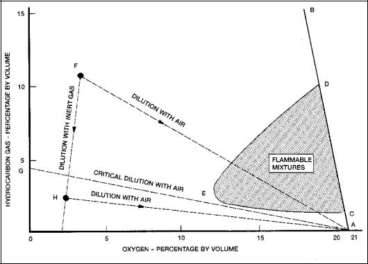
As inert gas is added to the hydrocarbon gas/air mixture, the flammable range decreases until a point, represented by E, is reached where the LFL and UFL coincide. This point corresponds to an oxygen content of approximately 11%. No hydrocarbon gas/air mixture can burn at this oxygen level. For practical purposes and to allow a safety margin, 8% is taken as the level of oxygen at which no hydrocarbon gas/air mixture can burn under any circumstances. To prevent fire or explosion in a tank containing a hydrocarbon gas/air mixture, it is therefore necessary to produce and supply inert gas having an oxygen content not normally exceeding 5% and to displace the existing air in the tank until the resultant oxygen level throughout the tank does not exceed 8% by volume.
Figure 7.1 Flammability Composition Diagram – Hydrocarbon Gas/Air/Inert
Gas Mixture
This diagram is illustrative only and should not be used for deciding upon acceptable gas compositions in practical cases.
The International Convention for the Safety of Life at Sea (SOLAS 1974), as amended, requires that inert gas systems be capable of delivering inert gas with an oxygen content in the inert gas main of not more than 5% by volume at any required rate of flow; and of maintaining a positive pressure in the cargo tanks at all times with an atmosphere having an oxygen content of not more than 8% by volume except when it is necessary for the tank to be gas free. Existing systems are only required to be capable of producing inert gas with an oxygen content not normally exceeding 5% by volume, and of maintaining the tank inerted at all times except when it is necessary for the tank to be gas free.
When air is introduced into an inert mixture, such as that represented by point F, its composition moves along the line FA and therefore enters the shaded area of flammable mixtures. This means that all inert mixtures in the region above the line GA (critical dilution line) pass through a flammable condition as they are mixed with air - for example, during a gas-freeing operation. Those below the line GA, such as that represented by point H, do not become flammable when air is mixed with them. It will be noted that it is possible to move from a mixture such as that represented by F, to one such as that represented by H, by the introduction of additional inert gas, i.e. by purging.
7.1.2SOURCES OF INERT GAS
Possible sources of inert gas on tankers and combination carriers are:
•Uptake gas from the ship’s main and auxiliary boilers.
•An independent inert gas generator.
•A gas turbine plant when equipped with an afterburner.
7.1.3COMPOSITION AND QUALITY OF INERT GAS
Inert gas must be delivered in the gas main with a maximum oxygen content of 5%. The oxygen content of inert gas in the cargo tanks must not exceed 8%.
When using flue gas from a main or auxiliary boiler, an oxygen level of less than 5% can generally be obtained, depending on the quality of combustion control and the load on the boiler.
When an independent inert gas generator or a gas turbine plant with afterburner is fitted, the oxygen content can be automatically controlled within finer limits, usually within the range 1.5% to 2.5% by volume, and not normally exceeding 5%.
In certain ports, the maximum oxygen content of inert gas in the cargo tanks may be set at 5% to meet particular safety requirements, such as the operation of a vapour emission control system. Where such a limitation is in place, the vessel is usually advised of the requirements in the pre-arrival information exchange.
Efficient scrubbing of the inert gas is essential, particularly for the reduction of the sulphur dioxide content. High levels of sulphur dioxide increase the acidic characteristic of the inert gas, which is harmful for personnel and may cause accelerated corrosion to the structure of a vessel.
The table below provides an indication of the typical composition of inert gas generated from boiler flue gas, expressed as a percentage by volume.
Nitrogen |
N2 |
83% |
Carbon dioxide |
CO2 |
12-14% |
Oxygen |
O2 |
2-4% |
Sulphur dioxide |
SO2 |
50 ppm |
Carbon monoxide |
CO |
Trace |
Nitrogen Oxide |
NOX |
Trace |
Water vapour |
H2O |
Trace (high if not dried) |
Ash and soot |
(C) |
Traces |
Density |
|
1.044 |
Table 7.1 Typical composition of inert gas at the scrubber outlet
7.1.4METHODS OF REPLACING TANK ATMOSPHERES
If the entire tank atmosphere could be replaced by an equal volume of inert gas, the resulting tank atmosphere would have the same oxygen level as the incoming inert gas. In practice, this is not the case and a volume of inert gas equal to several tank volumes must be introduced into the tank before the desired result can be achieved.
The replacement of a tank atmosphere by inert gas can be achieved by either inerting or purging. In each of these methods, one of two distinct processes, dilution or displacement, will predominate.
Dilution takes place when the incoming inert gas mixes with the original tank atmosphere to form a homogeneous mixture through the tank so that, as the process continues, the concentration of the original gas decreases progressively. It is important that the incoming inert gas has sufficient entry velocity to penetrate to the bottom of the tank. To ensure this, a limit must be placed on the number of tanks which can be inerted simultaneously. Where this is not clearly stipulated in the operations manual, only one tank should be inerted or purged at a time.
Displacement depends on the fact that inert gas is slightly lighter than hydrocarbon gas so that, while the inert gas enters at the top of the tank, the heavier hydrocarbon gas escapes from the bottom through suitable piping. When using this method, it is important that the inert gas has a very low velocity to enable a stable horizontal interface to be developed between the incoming and escaping gas. However, in practice, some dilution inevitably takes place owing to the turbulence caused in the inert gas flow. This method generally allows several tanks to be inerted or purged simultaneously.
Whatever method is employed, and whether inerting or purging, it is vital that oxygen or gas measurements are taken at several heights and horizontal positions within the tank to check the efficiency of the operation. A mixture of inert gas and petroleum gas, when vented and mixed with air, can become flammable. The normal safety precautions taken when petroleum gas is vented from a tank should therefore not be relaxed.
7.1.5CARGO TANK ATMOSPHERE CONTROL
7.1.5.1Inert Gas Operations
Tankers using an inert gas system should maintain their cargo tanks in a non-flammable condition at all times. It follows that:
•Tanks should be kept in an inert condition at all times, except when it is necessary for them to be gas free for inspection or work, i.e. the oxygen content should be not more than 8% by volume and the atmosphere should be maintained at a positive pressure.
•The atmosphere within the tank should make the transition from the inert condition to the gas free condition without passing through the flammable condition. In practice, this means that before any tank is gas freed, it should be purged with inert gas until the hydrocarbon content of the tank atmosphere is below the critical dilution line (line GA in Figure 7.1).
•When a ship is in a gas free condition before arrival at a loading port, the tanks must be inerted prior to loading.
In order to maintain cargo tanks in a non-flammable condition the inert gas plant will be required to:
•Inert empty cargo tanks (see Section 7.1.6.1).
•Be in operation during cargo discharge, deballasting, crude oil washing and tank cleaning (see Sections 7.1.6.6. and 7.1.6.9).
•Purge tanks prior to gas freeing (see Section 7.1.6.10).
•Top-up the pressure in the cargo tanks when necessary during other stages of the voyage (see Sections 7.1.6.5 and 7.1.6.7).
It must be emphasised that the protection provided by an inert gas system depends on the proper operation and maintenance of the entire system.
7.1.5.2Inert Gas System Maintenance
There should be close co-operation between the deck and engine departments to ensure the proper maintenance and operation of the inert gas system. It is particularly important to ensure that non-return barriers function correctly, especially the deck water seal or block and bleed valves, so that there is no possibility of petroleum gas or liquid petroleum passing back to the machinery spaces.
To demonstrate that the inert gas plant is fully operational and in good working order, a record of inspection of the inert gas plant, including defects and their rectification, should be maintained on board.
7.1.5.3Degradation of Inert Gas Quality
Tanker personnel should be alert to the possible degradation of inert gas quality as a result of air being drawn into the tanks due to inappropriate operation of the inert gas or cargo systems, for example, by:
•Not topping-up the inert gas promptly if the pressure in the system falls, for example, due to temperature changes at night.
•Prolonged opening of tank apertures for tank gauging, sampling and, dipping.
During tank entry operations, any draining of water from a non-inerted tank into the slop tank will result in entrainment of air into the drainings and, ultimately, into the inerted tank atmospheres via the slop tank. The volume of air entrained in this manner can be particularly high if an eductor is used on recirculation to the slop tank. If the liquid is to be drained to the slop tank, the inert gas quality in all tanks should be closely monitored.
7.1.6APPLICATION TO CARGO TANK OPERATIONS
7.1.6.1Inerting of Empty Tanks
Before the inert gas system is put into service, the tests required by the operations manual or manufacturer’s instructions should be carried out. The fixed oxygen analyser and recorder should be tested and proven to be in good order. Portable oxygen and hydrocarbon meters should also be prepared and tested. When inerting empty tanks which are gas free, for example following a dry-docking or tank entry, inert gas should be introduced through the distribution system while venting the air in the tank to the atmosphere.
This operation should continue until the oxygen content throughout the tank is not more than 8% by volume. Thereafter, the oxygen level will not increase if a positive pressure is maintained by using the inert gas system to introduce additional inert gas when necessary.
If the tank is not gas free, the precautions against static electricity given in Section 7.1.6.8 should be taken until the oxygen content of the tank has been reduced to 8%.
When all tanks have been inerted, they should be kept common with the inert gas main and the system pressurised with a minimum positive pressure of at least 100mm water gauge.
7.1.6.2Loading Cargo or Ballast into Tanks in an Inert Condition
When loading cargo or ballast, the inert gas plant should be shut down and the tanks vented through the appropriate venting system. On completion of loading or ballasting, and when all ullaging is completed, the tanks should be closed and the inert gas system restarted and repressurised. The system should then be shut down and all safety isolating valves secured.
Local regulations may prohibit venting after crude oil washing (see Section 11.5.8).
7.1.6.3Simultaneous Cargo/Ballast Operations
In the case of simultaneous loading and discharge operations involving cargo or ballast, venting to the atmosphere can be minimised, or possibly completely avoided, by interconnecting the tanks concerned through the inert gas main. Depending on the relative pumping rates, pressure in the tanks may be increased or a vacuum drawn, and it may therefore be necessary to adjust the inert gas flow accordingly to maintain tank pressures within normal limits.
7.1.6.4Vapour Balancing during Ship to Ship Transfers
Vapour balancing is used to avoid the release of any gases to the atmosphere through vents and to minimise the use of the inert gas systems when transferring cargo from ship to ship. The inert gas mains of the vessels are connected using a flexible hose. As a minimum, the following recommendations should be followed:
•Equipment should be provided on at least one of the vessels to enable the oxygen content of the vapour stream to be monitored. This should draw samples continuously from a location close to the vapour manifold connection and should include the facility for audible and visual alarms should the oxygen content of the vapour stream exceed 8% by volume. The oxygen analyser and associated alarms should be tested for proper function prior to each cargo transfer operation.
•The oxygen content of the vapour space of each tank connected to the IG main of both ships should be checked and confirmed to be less than 8% by volume.
•The vapour transfer hose should be purged of air and inerted prior to commencing transfer of vapours.
•The vapour manifold valves should not be opened until the pressure in the cargo system of the receiving vessel exceeds that of the vessel discharging cargo.
During the cargo transfer:
•The inert gas system on the discharging vessel should be kept operational and on stand-by, with the inert gas main deck isolating valve closed.
•The inert gas pressure on both ships should be monitored and each ship advised of the other’s pressure on a regular basis. The inert gas system should be used if the inert gas pressure in the discharging vessel falls to a low level (300mm wg).
•Transfer operations should be suspended if the oxygen content of the vapour stream exceeds 8% by volume and should only be resumed once the oxygen content has been reduced to 8% or less by volume.
•The cargo transfer rate must not exceed the design rate for the vapour balancing hose.
7.1.6.5Loaded Passage
A positive pressure of inert gas should be maintained in the ullage space at all times during the loaded passage in order to prevent the possible ingress of air. (See also Section 7.1.5.3). If the pressure falls below the low-pressure alarm level, it will be necessary to start the inert gas plant to restore an adequate pressure in the system.
Loss of pressure is normally associated with leakages from tank openings and falling air and sea temperatures. In these cases, it is all the more important to ensure that the tanks are gas tight. Gas leaks are usually easily detected by their noise and every effort must be made to eliminate leaks at tank hatches, ullage lids, tank cleaning machine openings, valves, etc.
Leaks which cannot be eliminated should be marked and recorded for sealing during the next ballast passage or at another suitable opportunity.
Certain oil products, principally aviation turbine kerosenes and diesel oil, can absorb oxygen during the refining and storage process. This oxygen can later be liberated into an oxygen deficient atmosphere such as the ullage space of an inerted cargo tank. Although the recorded incidence of oxygen liberation is low, cargo tank oxygen levels should be monitored so that any necessary precautionary measures can be taken prior to the commencement of discharge.
7.1.6.6Discharge of Cargo or Ballast from Tanks in an Inert Condition
The inert gas supply must be maintained through cargo or ballast discharge operations to prevent air entering the tanks. If, on arrival in port, the inert gas has to be de-pressurised in order to measure or sample the cargo, it may be difficult, because of the low boiler load, to re-pressurise with inert gas having a sufficiently low oxygen content. In this event, it may be necessary to create a load on the boiler by using the main cargo pumps to circulate the cargo around the ship’s pipelines until the inert gas quality is satisfactory. Great care is necessary to ensure that the pumping arrangements used for circulating cargo do not give rise to an overflow.
Throughout the discharge of cargo, particularly when the boiler load is low or fluctuating, the oxygen content of the inert gas supply must be carefully monitored.
If hand dipping of a tank is necessary, pressure may be reduced while dipping ports are open but care must be taken not to allow a vacuum to develop since this would pull air into the tank. To prevent this, it may be necessary to reduce the cargo pumping rate, and discharge should be stopped immediately if there is a danger of the tanks coming under vacuum.
Both the oxygen content and pressure of the inert gas main should be continuously recorded during discharge.
7.1.6.7Ballast Passage
During the ballast passage, tanks other than those required to be gas free, should remain in the inert condition and under positive pressure to prevent ingress of air. Whenever pressure falls to the low pressure alarm level, the inert gas plant should be restarted to restore the pressure, with due attention being paid to the oxygen content of the inert gas delivered.
7.1.6.8Static Electricity Precautions
In normal operations, the presence of inert gas prevents the existence of flammable gas mixtures inside cargo tanks. However, hazards due to static electricity may arise, mainly in the case of a failure of the inert gas system. To avoid these hazards the following procedures are recommended:
•If the inert gas plant breaks down during discharge, operations should be suspended. (See Section 7.1.12). If air has entered the tank, no dipping, ullaging, sampling or other equipment should be introduced into the tank until at least 30 minutes have elapsed since the injection of inert gas ceased. After this period equipment may be introduced provided that all metallic components are securely earthed. This requirement for bonding should be applied until a period of five hours has elapsed since the injection of inert gas ceased.
•During any necessary re-inerting of a tank following a failure and repair of the inert gas system, or during initial inerting of a non-gas free tank, no dipping, ullaging, sampling or other equipment should be inserted until the tank is in an inert condition, as established by monitoring the gas vented from the tank being inerted. However, should it be necessary to introduce a gas sampling system into the tank to establish its condition, at least 30 minutes should elapse after stopping the injection of inert gas before inserting the sampling system. Metallic components of the sampling system
should be electrically continuous and securely earthed. (See also Chapter 3 and Section 11.7).
7.1.6.9Tank Washing, including Crude Oil Washing
Before each tank is washed, the oxygen level must be determined, both at a point 1 metre below the deck and at the middle level of the ullage space. At neither of these locations should it exceed 8% by volume. Where tanks have a complete or partial swash bulkhead, the measurement should be taken from similar levels in each section of the tank. The oxygen content and pressure of the inert gas being delivered during the washing process should be continuously recorded.
If during washing, the oxygen level in the tank exceeds 8% by volume, or the pressure of the atmosphere in the tanks is no longer positive, washing must be stopped until satisfactory conditions are restored. (See also Section 7.1.12).
7.1.6.10Purging
When it is required to gas free a tank after washing, it should first be purged with inert gas to reduce the hydrocarbon content to 2% or less by volume. This is to ensure that during the subsequent gas freeing operation, no portion of the tank atmosphere is brought within the flammable range.
The hydrocarbon content must be measured with an appropriate meter designed to measure the percentage of hydrocarbon gas in an oxygen deficient atmosphere. The usual flammable gas indicator is not suitable for this purpose.
If the dilution method of purging is used, it should be carried out with the inert gas system set for maximum capacity to give maximum turbulence within the tank. If the displacement method is used, the gas inlet velocity should be lower to prevent undue turbulence.
7.1.6.11Gas Freeing
Before starting to gas free, the tank should be isolated from other tanks. When either portable fans or fixed fans connected to the cargo pipeline system are used to introduce air into the tank, the inert gas inlet should be isolated. If the inert gas system fan, drawing fresh air, is employed, both the line back to the inert gas source and the inert gas inlet into each tank being kept inerted, should be isolated.
7.1.6.12Preparation for Tank Entry
To ensure the dilution of the toxic components of inert gas to below their Threshold Limit Values (TLV), gas freeing should continue until tests with an oxygen analyser show a steady oxygen reading of 21% by volume and tests with a flammable gas indicator show not more than 1% LFL.
If the presence of a toxic gas, such as benzene or hydrogen sulphide, is suspected, gas freeing should be continued until tests indicate that its concentration is below its TLV.
Positive fresh air ventilation should be maintained throughout the period that personnel are in a tank, and frequent tests should be made of both oxygen and hydrocarbon content of the tank atmosphere.
When other tanks in an inert condition are either adjacent or interconnected (e.g. by a pipeline) to the tank being entered, personnel should be alert to the possibility of inert gas leaking into the gas free tank through, for example, bulkhead fractures or defective valves. The risk of this occurring can be minimised by maintaining a small but positive inert gas pressure. When a gas free tank is re-connected to the inert gas main, it should immediately be re-inerted.
For general advice on entry into enclosed spaces see Chapter 10.
7.1.7PRECAUTIONS TO BE TAKEN TO AVOID HEALTH HAZARDS
7.1.7.1Inert Gas on Deck
Certain wind conditions may bring vented gases back down onto the deck, even from specially designed vent outlets. Furthermore, if gases are vented at low level from cargo hatches, ullage ports or other tank apertures, the surrounding areas can contain levels of gases in harmful concentrations and may also be oxygen deficient. In these conditions, all non-essential work should cease and only essential personnel should remain on deck, taking all appropriate precautions.
When the last cargo carried was a sour crude, tests should also be made for hydrogen sulphide. If a level in excess of 10 ppm is detected, no personnel should be allowed to work on deck unless they are wearing suitable respiratory protection. (See Sections 1.2.6 and 11.1.9).
7.1.7.2Ullaging and Inspection of Tanks from Cargo Hatches
The low oxygen content of inert gas can cause rapid asphyxiation. Care should therefore be taken to avoid standing in the path of vented gas. (See Section 11.7.3).
7.1.7.3Entry into Cargo Tanks
Entry into cargo tanks should be permitted only after they have been gas freed, as described in Sections 7.1.6.10 and 7.1.6.11. The safety precautions set out in Chapter 10 should be observed and consideration given to the carriage of a personal oxygen deficiency alarm. If the hydrocarbon and oxygen levels specified in Section 7.1.6.12 cannot be achieved, entry should be permitted only in exceptional circumstances and when there is no practicable alternative.
Personnel must wear breathing apparatus under such circumstances. (See Section 10.7 for further details).
7.1.7.4Scrubber and Condensate Water
Inert gas scrubber effluent water is acidic. Condensate water, which tends to collect in the distribution pipes, particularly in the deck main, is often more acidic than the scrubber effluent and is highly corrosive.
Care should be taken to avoid unnecessary skin contact with either effluent or condensate water. Particular care should also be taken to avoid accidental contact with the eyes and protective goggles should be worn whenever there is a risk of such contact.
7.1.8CARGO TANK PROTECTION
A number of serious incidents have occurred on oil tankers due to cargo tanks being subjected to extremes of over or under pressure. Whilst SOLAS Regulations have been modified to require tanks to be fitted with full flow pressure relief devices or individual tank pressure monitoring, it is still essential that venting systems are thoroughly checked to ensure that they are correctly set for the intended operation. Once operations have started, further checks should be made for any abnormalities, such as unusual noises of vapour escaping under pressure or pressure/vacuum valves lifting.
Ship’s personnel should be provided with clear, unambiguous operating procedures for the proper management and control of the venting system and should have a full understanding of its capabilities.
7.1.8.1Pressure/Vacuum Breakers
Every inert gas system is required to be fitted with one or more pressure/vacuum breakers or other approved devices. These are designed to protect the cargo tanks against excessive pressure or vacuum and must therefore be kept in good working order by regular maintenance in accordance with the manufacturer’s instructions.
When these breakers are liquid filled, it is important to ensure that the correct fluid is used and the correct level is maintained. The level can normally only be checked when there is no pressure in the inert gas main line. Evaporation, condensation and possible ingress of sea water should be taken into consideration when checking the liquid condition and level. In heavy weather, the pressure surge caused by the motion of liquid in the cargo tanks may cause the liquid in the pressure/vacuum breaker to be blown out. This may be more liable to happen on combination carriers than on tankers.
7.1.8.2Pressure/Vacuum Valves
These are designed to provide for the flow of the small volumes of tank atmosphere caused by thermal variations in a cargo tank and should operate in advance of the pressure/vacuum breakers. To avoid unnecessary operation of the pressure/vacuum breaker, the pressure/vacuum valves should be kept in good working order by regular inspection and cleaning.
7.1.8.3Full Flow Pressure/Vacuum Venting Arrangements
In inert gas systems fitted with tank isolating valves, protection from over and under pressurisation of the cargo tanks may be provided by using high velocity vent and vacuum valves as the full flow protection device. Where this is the case, particular attention should be paid to ensuring that the valves operate at the required pressure and vacuum settings. Planned maintenance procedures should be established to maintain and test these safety devices.
7.1.8.4Individual Tank Pressure Monitoring and Alarm Systems
In inert gas systems fitted with tank isolating valves, indication of the possible over and under pressurisation of the cargo tank is provided by using individual tank pressure sensors connected to an alarm system. Where such systems are used, planned maintenance procedures should be established to maintain and test these sensors and confirm that they are providing accurate readings.
7.1.9EMERGENCY INERT GAS SUPPLY
The International Convention for the Safety of Life at Sea (SOLAS 1974), as amended, requires that suitable arrangements are provided to enable the inert gas system to be connected to an external supply of inert gas.
These arrangements should consist of a 250 mm nominal pipe size bolted flange, isolated from the inert gas main by a valve and located forward of the non-return valve. The design of the flange should be compatible with the design of other connections in the ship’s cargo piping system.
7.1.10PRODUCT CARRIERS REQUIRED TO BE FITTED WITH AN INERT GAS
SYSTEM
7.1.10.1General
The basic principles of inerting are exactly the same on product carriers as on crude carriers.
There are, however, some differences in operational detail, as outlined in the following sections.
7.1.10.2Carriage of Products Having a Flashpoint Exceeding 60ºC
The 1974 SOLAS Convention, as amended, implies that tankers may carry petroleum products having a flashpoint exceeding 60ºC (i.e. bitumens, lubricating oils, heavy fuel oils, high flashpoint jet fuels and some diesel fuels, gas oils and special boiling point liquids) without inert gas systems having to be fitted or, if fitted, without tanks containing such cargoes having to be kept in the inert condition.
However, when cargoes with a flashpoint exceeding 60ºC are carried at a cargo temperature higher than their flashpoint less 5ºC, the tanks should be maintained in an inert condition because of the danger that a flammable condition may occur.
It is recommended that, if inert gas systems are fitted, cargo tanks are maintained in an inert condition whenever there is a possibility that the ullage space atmosphere could be within the flammable range. (See also Section 1.6 regarding the carriage of residual fuel oils).
When a non-volatile cargo is carried in a tank that has not been previously gas freed, the tank should be maintained in an inert condition.
7.1.10.3 Additional Purging and Gas Freeing
Gas freeing is required on product carriers more frequently than on crude carriers, because of the greater need both for tank entry and inspection, especially in port, and for venting the vapours of previous cargoes. On inerted product carriers, any gas freeing operation has to be preceded by a purging operation. (See Section 7.1.6.10).
It should be recognised, however, that purging is not essential before gas freeing when the hydrocarbon gas content of a tank is already below 2% by volume.
7.1.11COLD WEATHER PRECAUTIONS FOR INERT GAS SYSTEMS
The inert gas system may be subjected to operational faults when operating in extreme cold weather conditions.
7.1.11.1Condensation in Inert Gas Piping
SOLAS requires that the piping system shall be so designed as to prevent accumulation of cargo or water in the pipeline under all normal conditions. However, in extreme cold conditions, carried-over water in the inert gas may freeze in the inert gas main. Operators need to be aware of this and operate the system to minimise water carry-over and closely monitor the system’s operation.
7.1.11.2Control Air
Air operated control valves fitted to the inert gas system outside the engine room may not operate correctly if exposed to extremely low ambient temperatures if the control air has a high water vapour.
Water separators in control air systems should be drained frequently and the control air dryers should be checked regularly for efficient operation.
7.1.11.3Safety Devices
In extremely cold weather, ice may prevent the pressure/vacuum valves from operating and may block the flame screens on the pressure/vacuum valves and mast risers.
Water filled pressure/vacuum breakers should be filled to the appropriate level with antifreeze liquid.
Deck water seals are filled with heating coils and these coils should be put into operation prior to experiencing cold weather conditions.
7.1.11.4Sea chests
To ensure the water supply to the scrubber and deck seal is maintained when experiencing ice conditions at sea or in estuaries, the low sea water suctions should be used. This will reduce the probability of ice slurry being drawn into the sea chest. Steam injection connections to sea chests should be fully operational to assist in clearing sea chests, should it become necessary.
7.1.12INERT GAS SYSTEM FAILURE
The SOLAS convention requires each ship fitted with an inert gas system to have a manual containing detailed guidance on the operation, safety and maintenance requirements, and the occupational health hazards relevant to the installed system. The manual must include guidance on procedure to be followed in the event of a fault or failure of the inert gas system.
7.1.12.1Action to be Taken on Failure of the Inert Gas System
In the event of the failure of the inert gas system to deliver the required quality and quantity of inert gas, or to maintain a positive pressure in the cargo tanks and slop tanks, action must be taken immediately to prevent any air being drawn into the tanks. All cargo and/or ballast discharge must be stopped, the inert gas deck isolating valve closed, the vent valve between it and the gas pressure regulating valve (if provided) opened, and immediate action taken to repair the inert gas system.
Masters are reminded that national and local regulations may require the failure of an inert gas system to be reported to the harbour authority, terminal operator and to the port and flag state administrations.
7.1.12.2Follow up Action on Crude Oil Tankers
In crude oil tankers, pyrophoric iron sulphide deposits, formed when hydrogen sulphide gas reacts with rusted surfaces in the absence of oxygen, may be present in the cargo tanks and these deposits can heat to incandescence when coming into contact with air. Therefore, in the case of tankers engaged in the carriage of crude oil, the failed inert gas system must be repaired and restarted, or an alternative source of inert gas provided, before discharge of the cargo or ballast is resumed.
7.1.12.3Follow up Action on Product Tankers
In the case of product carriers, the formation of pyrophors is usually inhibited by tank coatings. Therefore, if it is considered totally impracticable to repair the inert gas system, discharge may be resumed with the written agreement of all interested parties, provided that an external source of inert gas is provided or detailed procedures are established to ensure the safety of operations. The following precautions should be taken:
•Devices to prevent the passage of flame or flame screens (as appropriate) are in place and are checked to ensure that they are in a satisfactory condition.
•Valves on the vent mast risers are opened.
•No free fall of water or slops is permitted.
•No dipping, ullaging, sampling or other equipment is introduced into the tank unless essential for the safety of the operation. If it is necessary for such equipment to be introduced into the tank, it should only be done only after at least 30 minutes have elapsed since the injection of inert gas has ceased. (See Section 7.1.6.8 for static precautions relating to inert gas and Sections 11.1.7 for general static precautions).
•All metal components of any equipment to be introduced into the tank should be securely earthed. This restriction should be applied until a period of five hours has elapsed since the injection of inert gas ceased.
7.1.13INERT GAS PLANT REPAIRS
As inert gas causes asphyxiation, great care must be taken to avoid the escape of inert gas into any enclosed or partly enclosed space.
Before opening the system, if possible, it should be gas freed and any enclosed space in which the system is opened up should be ventilated to avoid any risk of oxygen deficiency.