

Nitric oxide is a colourless gas with little smell at its TLV-TWA of 25 ppm. Nitrogen dioxide is even more toxic with a TLV-TWA of 3 ppm.
1.2.9.4Sulphur Dioxide
Flue gas produced by the combustion of fuel oil having a high sulphur content typically
contains about 2,000 ppm of sulphur dioxide (SO2). Inert gas system water scrubbers remove this gas with an efficiency that depends upon the design and operation of the scrubber, giving inert gas with a sulphur dioxide content of typically between 2 and 50 ppm.
Sulphur dioxide causes irritation of the eyes, nose and throat and may also cause breathing difficulties in sensitive people. It has a distinctive smell at its TLV-TWA of 2 ppm.
1.2.9.5Carbon Monoxide
Carbon monoxide (CO) is normally present in flue gas at a level of only a few parts per million, but abnormal combustion conditions and slow running can give rise to levels in excess of 200 ppm. Carbon monoxide is an odourless gas with a TLV-TWA of 25ppm. It is insidious in its attack, which is to restrict oxygen uptake by the blood, causing a chemically induced form of asphyxiation.
1.2.10OXYGEN DEFICIENCY
The oxygen content of the atmosphere in enclosed spaces may be low for several reasons. The most obvious one is if the space is in an inert condition, and the oxygen has been displaced by the inert gas. Oxygen may also be removed from an atmosphere by chemical reactions, such as rusting or the hardening of paints or coatings.
As the amount of available oxygen decreases below the normal 21% by volume, breathing tends to become faster and deeper. Symptoms indicating that an atmosphere is deficient in oxygen may give inadequate notice of danger. Most persons would fail to recognise the danger until they were too weak to be able to escape without help. This is especially so when escape involves the exertion of climbing.
While individuals vary in susceptibility, all will suffer impairment if the oxygen level falls to 16% by volume.
Exposure to an atmosphere containing less than 10% oxygen content by volume inevitably causes unconsciousness. The rapidity of onset of unconsciousness increases as the availability of oxygen diminishes, and death will result unless the victim is removed to the open air and resuscitated.
An atmosphere containing less than 5% oxygen by volume causes immediate unconsciousness with no warning other than a gasp for air. If resuscitation is delayed for more than a few minutes, irreversible damage is done to the brain, even if life is subsequently restored.
1.3GAS MEASUREMENT
1.3.1INTRODUCTION
This Section describes the principles, uses and limitations of portable instruments for measuring concentrations of hydrocarbon gas (in inerted and non-inerted atmospheres), other toxic gases and oxygen. Certain fixed installations are also described. For detailed information on the use of all instruments, reference should always be made to the manufacturer’s instructions.
1.3.2MEASUREMENT OF HYDROCARBON CONCENTRATION
The measurement of hydrocarbon vapours on tankers and at terminals falls into two categories:
1.The measurement of hydrocarbon gas in air at concentrations below the Lower
Flammable Limit (LFL).
This is to detect the presence of flammable (and potentially explosive) vapours and to detect concentrations of hydrocarbon vapour that may be harmful to personnel. These readings are expressed as a percentage of the Lower Flammable Limit (LFL) and are usually recorded as %LFL. The instruments used to measure %LFL are Catalytic Filament Combustible Gas Indicators, which are usually referred to as Flammable Gas Monitors or Explosimeters.
2.The measurement of hydrocarbon gas as a percentage by volume of the total atmosphere being measured.
Onboard a tanker, this is usually carried out to measure the percentage of hydrocarbon vapour in an inerted atmosphere. Instruments used to measure hydrocarbon vapours in an inert gas atmosphere are specially developed for this purpose. The readings obtained are expressed as the percentage of hydrocarbon vapour by volume and are recorded as % VOL.
The instruments used to measure percentage hydrocarbon vapours in inert gas are Non-catalytic Heated Filament Gas Indicators and are usually referred to as Tankscopes. Modern developments in gas detection technology have resulted in the introduction of electronic instruments using infra-red sensors which, when suitably designed, can perform the same function as the Tankscope.
1.3.3FLAMMABLE GAS MONITORS (EXPLOSIMETER)
Modern instruments have a poison resistant flammable pellistor as the sensing element. Pellistors rely on the presence of Oxygen (minimum 11% by volume) to operate efficiently and for this reason Explosimeters must not be used for measuring hydrocarbon gas in inert atmospheres.
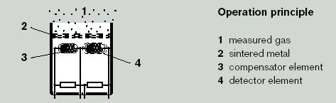
1.3.3.1Operating Principle
A simplified diagram of the electrical circuit incorporating a pellistor in a Wheatstone Bridge is shown in Figure 1-1.
Unlike in early Explosimeters, the pellistor unit balances the voltage and zeros the display automatically when the instrument is switched on in fresh air. In general, it takes about 30 seconds for the pellistor to reach its operating temperature. However, the operator should always refer to the manufacturer’s instructions for the start up procedure.
Figure 1.1 Pellistor
A gas sample may be taken in several ways:
•Diffusion.
•Hose and aspirator bulb (1 squeeze equates to about 1 metre of hose length).
•Motorised pump (either internal or external).
Flammable vapours are drawn through a sintered filter (flash back arrestor) into the pellistor combustion chamber. Within the chamber are two elements, the ‘Detector’ and the ‘Compensator’ This pair of elements is heated to between 400 and 600° C. When no gas is present, the resistances of the two elements are balanced and the bridge will produce a stable baseline signal. Combustible gases will catalytically oxidise on the detector head causing its temperature to rise. This oxidisation can only take place if there is sufficient oxygen present.
The reading is taken when the display is stable.
Care should be taken to ensure that liquid is not drawn into the instrument. The use of an inline water trap and a float probe fitted to the end of the aspirator hose should prevent this occurrence. Most manufacturers offer these items as accessories.
Modern units will indicate on the display when the gas sample has exceeded the LFL.
1.3.3.2Cautions
Some vapours can reduce the sensitivity of the flammable pellistor:
Poisons - these are compounds that can permanently affect the performance of the pellistor and include silicone vapours and organic lead compounds.
Inhibitors – these compounds act in a very similar way to poisons, except that the reaction is reversible. They include hydrogen sulphide, freons and chlorinated hydrocarbons. If the presence of hydrogen sulphide is suspected, this should be tested for before any measurements of hydrocarbon vapours are carried out. (See Section 1.3.7).
An explosimeter does not give a reliable reading with atmospheres deficient in oxygen, such as those present in inerted or partially inerted tanks. The meter must not be used for measuring hydrocarbon concentrations in inerted atmospheres.
Pellistor type instruments should not have their sensors subjected to pressure as this will damage the pellistor.
Such pressurisation may occur when testing for gas in the following conditions:
•Inert gas under high pressure or at high velocity, such as from a purge pipe or high velocity vent
•Hydrocarbon gas mixtures at high velocity in vapour lines or from a high velocity vent
The above is also relevant when using multi-gas instruments. For example, when an infrared sensor is being utilised for taking a % Vol gas reading, any pellistor sensor in the instrument may suffer damage if the inlet gas stream into the instrument is at a pressure or has a high velocity.
Pellistor instruments will not indicate the presence of combustible mists (such as lubricating oils) or dusts.
The performance of pellisters may be temporarily affected by condensation. This can occur when the instrument is taken into a humid atmosphere after it has been in an airconditioned environment. Time should be allowed for instruments to acclimatise to the operating temperature before they are used.
The instrument is normally fitted with a filter to remove solid particles and liquid.
1.3.3.3Instrument Check Procedures
An Explosimeter is not a precision instrument and it can only indicate the presence of all flammable vapours in the atmosphere being tested. The istrument will indicate a value representing the mixture of hydrocarbon vapours present. The only time the instrument is accurate is when it is measuring the same gas with which it has been calibrated.
The instrument is set up in the factory to be calibrated using a specific hydrocarbon gas/air mixture. The hydrocarbon gas which should be used for calibration and testing should be indicated on a label fixed to the instrument.
The instrument’s response should be checked prior to use.
The instrument should be re-calibrated by a competent person in accordance with the relevant Safety Management System procedures and manufacturer’s instructions.
During operation, it is important to occasionally check the instrument and sample lines for leakage, since the ingress of air would dilute the sample, resulting in false readings.
Leak testing may be achieved by pinching the sample line and squeezing the aspirator bulb. The bulb should not expand as long as the sample line is pinched.
1.3.3.4Precision of Measurement
The response of the instrument depends upon the composition of the hydrocarbon gas being tested and, in practice, this composition is not known. By using propane or butane as the calibration gas for an instrument being used on tankers carrying stabilised crude oil or petroleum products, the readings provided may be slightly in error by giving a slightly high reading. This ensures that any reading indicated will be “on the safe side”.
Factors that can affect the measurements are large changes in ambient temperature and excessive pressure of the tank atmosphere being tested, leading to high flow rates which in turn affect the pellistor temperature.
The use of dilution tubes, which enable catalytic filament indicators to measure concentrations in over rich hydrocarbon gas/air mixtures, is discouraged.
1.3.3.5Operational Features
Older instruments are fitted with flashback arresters in the inlet and outlet of the detector filament chamber. The arresters are essential to prevent the possibility of flame propagation from the combustible chamber and a check should always be made to ensure that they are in place and fitted properly. Modern pellistor type instrument have sintered filters usually built into the pellistor body.
Some authorities require, as a condition of their approval, that PVC covers be fitted around meters with aluminium cases to avoid the risk of incendive sparking if the case impacts on rusty steel.
Only cotton filters should be used to remove solid particles or liquid from the gas sample when hydrocarbons are being measured. Water traps may be used to protect the instrument where the sampled gas may be very wet.
Guidelines on the use of filters and traps will be found in the operating manual for the instrument. (See also Section 1.3.14).
1.3.4TANKSCOPE (NON-CATALYTIC HEATED FILAMENT GAS INDICATOR)
1.3.4.1Operating Principle
The sensing element of this instrument is usually a non-catalytic hot filament. The composition of the surrounding gas determines the rate of loss of heat from the filament, and hence its temperature and resistance.
The sensor filament forms one arm of a Wheatstone Bridge. The initial zeroing operation balances the bridge and establishes the correct voltage across the filament, thus ensuring the correct operating temperature. During zeroing, the sensor filament is purged with air or inert gas free from hydrocarbons. As in the Explosimeter, there is a second identical filament in another arm of the bridge which is kept permanently in contact with air and acts as a compensator filament.
The presence of hydrocarbon changes the resistance of the sensor filament and this is shown by a deflection on the bridge meter. The rate of heat loss from the filament is a non-linear function of hydrocarbon concentration and the meter scale reflects this nonlinearity. The meter gives a direct reading of % volume hydrocarbons.
In taking a measurement, the manufacturer’s detailed instructions should be followed. After the instrument has been initially set at zero with fresh air in contact with the sensor filament, a sample is drawn into the meter by means of a rubber aspirator bulb. The bulb should be operated until the meter pointer comes to rest on the scale (usually within 15-20 squeezes) then aspirating should be stopped and the final reading taken. It is important that the reading should be taken with no flow through the instrument and with the gas at normal atmospheric pressure.
The non-catalytic filament is not affected by gas concentrations in excess of its working scale. The instrument reading goes off the scale and remains in this position as long as the filament is exposed to the rich gas mixture.
1.3.4.2Instrument Check Procedures
The checking of a non-catalytic heated filament instrument requires the provision of gas mixtures of a known total hydrocarbon concentration.
The carrier gas may be air, nitrogen or carbon dioxide or a mixture of these. Since this type of instrument may be required to measure accurately either low concentrations (1%- 3% by volume) or high concentrations (greater than 10% by volume) it is desirable to have either two test mixtures, say 2% and 15% by volume, or one mixture between these two numbers, say 8% by volume. Test gas mixtures may be obtained in small aerosol-type dispensers or small pressurised gas cylinders, or may be prepared in a special test kit.
1.3.4.3Precision of Measurement
Correct response from these instruments is achieved only when measuring gas concentrations in mixtures for which the instrument has been calibrated and which remain gaseous at the temperature of the instrument.
Relatively small deviations from normal atmospheric pressure in the instrument produce significant differences in the indicated gas concentration. If a space which is under elevated pressure is sampled, it may be necessary to detach the sampling line from the instrument and allow the sample pressure to equalise with the atmosphere pressure.
1.3.4.4Instruments with Infra Red Sensors
When selecting an instrument that uses an infra-red sensor for measuring the percentage by volume of hydrocarbon in an inert gas atmosphere, care should be taken to ensure that the sensor will provide accurate readings over the spectrum of gases likely to be present in the atmosphere to be measured. It may be prudent to make comparison readings with a Tankscope to verify the acceptability of the readings provided by the instrument under consideration.
1.3.5INFEROMETER (REFRACTIVE INDEX METER)
1.3.5.1Operating Principle
An inferometer is an optical device that utilises the difference between the refractive indices of the gas sample and air.
In this type of instrument, a beam of light is divided into two, and these are then recombined at the eyepiece. The recombined beams exhibit an interference pattern which appears to the observer as a number of dark lines in the eyepiece.
One light path is through chambers filled with air. The other path is via chambers through which the sample gas is pumped. Initially, the latter chambers are filled with air and the instrument is adjusted so that one of the dark lines coincides with the zero line on the instrument scale. If a gas mixture is then pumped into the sample chambers the dark lines are displaced across the scale by an amount proportional to the change of refractive index.
The displacement is measured by noting the new position on the scale of the line which was used initially to zero the instrument. The scale may be calibrated in concentration units or it may be an arbitrary scale whose readings are converted to the required units by a table or graph.
The response of the instrument is linear and a one-point test with a standard mixture at a known concentration is sufficient for checking purposes.
The instrument is normally calibrated for a particular hydrocarbon gas mixture. As long as the use of the instrument is restricted to the calibration gas mixture it provides accurate measurements of gas concentrations.
The measurement of the concentration of hydrocarbon gas in an inerted atmosphere is affected by the carbon dioxide present when flue gas is used for inerting. In this case the use of soda-lime as an absorbent for carbon dioxide is recommended, provided the reading is corrected appropriately.
The refractive index meter is not affected by gas concentrations in excess of its scale range. The instrument reading goes off the scale and remains in this position as long as the gas chambers are filled with the gas mixture.
1.3.5.2Instrument Check Procedures
A mixture of known hydrocarbon, e.g. propane in nitrogen at a known concentration, should be used to check the instrument. If the hydrocarbon test gas differs from the original calibration gas, the indicated reading should be multiplied by the appropriate correction factor before judging the accuracy and stability of the instrument.
1.3.6INFRA-RED INSTRUMENTS
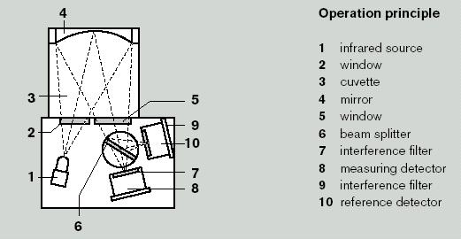
1.3.6.1Operating Principle
Figure 1.2 - Infrared Sensor
The Infra-red (IR) sensor is a transducer for the measurement of the concentration of hydrocarbons in the atmosphere, by the absorption of infra-red radiation.
The vapour to be monitored reaches the measuring chamber by diffusion or by means of a pump. Infra-red light radiation from the light source, shines through a window into the chamber, is reflected and focussed by the spherical mirror, and then passes through another window and hits the beam splitter. The portion of the radiation which passes the beam splitter passes through a broad band interference filter (= measuring filter) into the housing cover of the measuring detector and is converted into an electric signal.
The portion of the radiation reflected by the beam splitter passes the reference filter to reach the reference detector.
If the gas mixture in the chamber contains hydrocarbons, a part of the radiation is absorbed in the wavelength range of the measurement filter, and a reduced electric signal is given. At the same time, the signal of the reference detector remains unchanged. Gas concentration is determined by comparing the relative values between the reference indicator and the measuring detector.
Differences in the output of the IR light source, dirt on mirrors and windows as well as dust of aerosols contained in the air have an identical impact on both detectors and are therefore compensated.
1.3.6.2Instrument Check Procedures
This instrument should be checked using a check gas of a known mixture of hydrocarbons. The IR sensor does not require the presence of air or inert gas in the gas concentration as it is reliant solely on the hydrocarbon molecules. In general, these instruments are very stable and require little maintenance. Calibration should be frequently checked in accordance with the manufacturer’s instructions and Safety Management System procedures.
1.3.7MEASUREMENT OF LOW CONCENTRATIONS OF TOXIC GASES
1.3.7.1Chemical Indicator Tubes
Probably the most convenient and suitable equipment to use for measuring very low concentrations of toxic gases on board tankers is the chemical indicator tube.
These consist of a sealed glass tube containing a proprietary filling which is designed to react with a specific gas and to give a visible indication of the concentration of that gas. To use the device the seals at each end of the glass tube are broken, the tube is inserted in a bellows-type fixed volume displacement hand pump, and a prescribed volume of gas mixture is drawn through the tube at a rate fixed by the rate of expansion of the bellows. A colour change occurs along the tube and the length of discolouration, which is a measure of the gas concentration, is read off a scale integral with the tube.
In some versions of these instruments, a hand operated injection syringe is used instead of a bellows pump.
It is important that all the components used for any measurement should be from the same manufacturer. It is not permissible to use a tube from one manufacturer with a hand pump from another manufacturer. It is also important that the manufacturer’s operating instructions are carefully observed.
Since the measurement depends on passing a fixed volume of gas through the glass tube, any use of extension hoses should be in strict accordance with manufacturer’s instructions.
The tubes are designed and intended to measure concentrations of gas in the air. As a result, measurements made in a ventilated tank, in preparation for tank entry, should be reliable.
Under some circumstances, errors can occur if several gases are present at the same time, as one gas can interfere with the measurement of another. The manufacturer’s operating instructions should be consulted prior to testing such atmospheres.
For each type of tube, the manufacturers must guarantee the standards of accuracy laid down in national standards. Tanker operators should consult the vessel’s flag administration for guidance on acceptable equipment.
1.3.7.2Electrochemical Sensors
Electrochemical sensors are based on the fact that cells can be constructed that react with the measured gas and generate an electric current. This can be measured and the amount of gas determined as a result. The sensors are low cost and are small enough to allow several to be incorporated into the same instrument, making them for use in multi gas detectors.
There are numerous electrochemical sensors available, covering a number of gases which may be present in the shipboard environment, such as, ammonia, hydrogen sulphide, carbon monoxide, carbon dioxide and sulphur dioxide.
The electrochemical sensors may be used in stand-alone instruments, which may provide a warning at a predetermined concentration of vapour, or they may be fitted in a multisensor instrument to provide a reading of the concentration of the vapour, usually in parts per million (ppm).
These sensors may give erroneous readings due to cross-sensitivity. This occurs for
example, when measuring toxic gases with hydrocarbon gases present, for example, H2S in the presence of nitric oxide and sulphur dioxide.
1.3.8FIXED GAS DETECTION INSTALLATIONS
Fixed gas detection installations have been employed to a limited extent in a few petroleum tankers to monitor the flammability of the atmosphere in spaces such as double hull spaces, pumprooms and pipe tunnels in double bottoms.
Three general arrangements have been developed for fixed monitoring installations, as follows:
•A multiplicity of sensing devices is distributed throughout the spaces to be monitored. Signals are taken sequentially from them by a central control.
•A gas measurement system is installed in the central control room. Samples of the atmospheres to be checked are drawn sequentially, usually by vacuum pump, through sample lines to the central gas measurement system. It is important to ensure that there is no leakage of air into the system which would dilute the samples and cause misleading readings.
•Infra-red sensors are located in the space being monitored and the electronics necessary for processing the signals are located in a safe location, usually the central control room.
1.3.9MEASUREMENT OF OXYGEN CONCENTRATIONS
Oxygen analysers are normally used to determine whether an atmosphere, for example, inside a cargo tank, may be considered fully inerted or safe for entry. Fixed types of analysers are used for monitoring the oxygen content of the boiler uptakes and the inert gas main.
The following are the most common types of oxygen analysers in use:
•Paramagnetic sensors.
•Electrolytic sensors.
All analysers, regardless of type, should be used strictly in accordance with the manufacturer’s instructions. If so used, and subject to the limitations listed below, the analysers may be regarded as reliable.
1.3.10USE OF OXYGEN ANALYSERS
1.3.10.1Paramagnetic Sensors
Oxygen is strongly paramagnetic, whereas most other common gases are not. This property therefore enables oxygen to be determined in a wide variety of gas mixtures.
One commonly used oxygen analyser of the paramagnetic type has a sample cell in which a lightweight body is suspended in a magnetic field. When sample gas is drawn through the cell, the suspended body experiences a torque proportional to the magnetic susceptibility of the gas. An equal and opposing torque is produced by an electric current passing through a coil wound round the suspended body. The equalising current is a measure of the magnetic force and is thus a measure of the magnetic susceptibility of the sample, i.e. related to its oxygen content.
Before use, the analyser should be calibrated, using nitrogen or carbon dioxide to purge the sample cell for a zero check and with air at 21% oxygen for span.
[Note: Releasing nitrogen or carbon dioxide in a confined or unventilated area can lower the concentration of oxygen to a level that is immediately dangerous to life or health. Calibration should therefore only be carried out in well ventilated areas.]
The analyser readings are directly proportional to the pressure in the measuring cell. The unit is calibrated to a specific atmospheric pressure and the small error due to atmospheric pressure variations can be corrected if required. Reading errors can be more significant during pressure variations using some gas sampling arrangements, but can be avoided by reducing the sampling pressure to atmospheric during readings. Continuous samples should be supplied to the instrument by positive pressure. They should not be drawn through the analyser by negative pressure as the measuring pressure then becomes uncertain.
The filter should be cleared or replaced when an increase in sample pressure is required to maintain a reasonable gas flow through the analyser. The same effect is produced if the filter becomes wet due to insufficient gas drying. The need for filter cleaning or replacement should be checked regularly.
1.3.10.2Electrochemical Sensors
Analysers of this type determine the oxygen content of a gas mixture by measuring the output of an electrochemical cell. In one commonly-used analyser, oxygen diffuses through a membrane into the cell, causing current to flow between two special electrodes separated by a liquid or gel electrolyte.
The current flow is related to the oxygen concentration in the sample and the scale is arranged to give a direct indication of oxygen content. The cell may be housed in a separate sensor head connected by cable to the read-out unit.
The analyser readings are directly proportional to the pressure in the measuring cell but only small errors are caused by normal variations in atmospheric pressure.
Certain gases may affect the sensor and give rise to false readings. Sulphur dioxide and oxides of nitrogen interfere if they are present in concentrations of more than 0.25% by volume. Mercaptans and hydrogen sulphide can poison the sensor if their levels are greater than 1% by volume. This poisoning does not occur immediately but over a period of time; a poisoned sensor drifts and cannot be calibrated in air. In such cases reference should be made to the manufacturer’s instructions.
1.3.10.3Maintenance, Calibration and Test Procedures
As these oxygen analysers are of vital importance, they should be carefully maintained and tested strictly in accordance with the manufacturer’s instructions.
It is essential that each time an instrument is to be used, a check is made of batteries (if fitted), zero setting and calibration. During use, frequent checks should be made to ensure accurate readings are obtained at all times. Calibration is simple on all analysers, using atmospheric air as standard. Zero calibration can be checked with nitrogen, for electrochemical sensors, or carbon dioxide, for instruments with paramagnetic sensors.
1.3.11MULTI GAS INSTRUMENTS
Multi gas instruments are now widely used and are usually capable of housing four different sensors. A typical configuration would comprise of sensors for measuring:
•Hydrocarbon vapour as a %LFL (Explosimeter function using a pellistor sensor).
•Hydrocarbon vapour in inert gas as a %Vol (Tankscope function using an infra red sensor).
•Oxygen (using an electrochemical sensor).
•Hydrogen Sulphide (using an electrochemical sensor).
All these monitors should be tested at regular intervals in accordance with manufactuer’s instructions.
Multi gas instruments may be supplied for gas measurement use and be fitted with a data logging capability, but without an alarm function.
Care must be taken when using multi-gas instruments to check for hydrocarbons in an inerted atmosphere under pressure as the pellistor within the instrument could be damaged if subjected to pressure. (See Section 1.3.3.2).
1.3.12PERSONAL GAS MONITORS
Multi gas instruments may also be supplied as compact units fitted with an alarm function for personal protective use during tank entry. These personal monitors are capable of continuously measuring the content of the atmosphere by diffusion. They usually employ up to four electrochemical sensors and should automatically provide an audible and visual alarm when the atmosphere becomes unsafe, thereby giving the wearer adequate warning of unsafe conditions.
Disposable personal gas monitors are now available. They usually provide protection against a single gas and are available for low oxygen level, and high concentrations of hydrocarbons and other toxic vapours. The units should provide both audible and visual warning at specified levels of vapour concentration, which should be at or below the TLVSTEL for the monitored vapour. Typically, these monitors weigh less than 100 grams and have a life of about 2 years.
1.3.13GAS SAMPLE LINES AND SAMPLING PROCEDURES
1.3.13.1Gas Sample Lines
The material and condition of sample lines can affect the accuracy of gas measurements.
Metal tubes are unsuited to most cargo tank gas measurements and flexible lines must be used.
The gases from crude oils and many petroleum products are composed essentially of paraffinic hydrocarbons and there are a number of suitable materials available for flexible sample tubing. The problem of material selection is more difficult for those gases containing substantial proportions of aromatic hydrocarbons, in particular xylene. It is
recommended that in such cases suppliers of sample tubing should be asked to provide test data showing the suitability of their product for the purposes for which it will be employed.
Sample tubing must be resistant to water.
Sample tubing which is cracked or blocked, or which has become contaminated with cargo residues, greatly affects instrument readings. Users should check the condition of the tubing regularly and replace any found to be defective.
In order to prevent liquid from being drawn up the gas sampling line and causing contamination of the line, manufacturers provide a float termination or a probe termination to prevent the ingress of liquid. Operators should consider using these fittings but should be aware of any limitations on their use to avoid static hazards.
1.3.13.2Sampling Procedures
Every tank has ‘dead spots’ where the rate of change of gas concentration during ventilation or purging is less than the average in the bulk of the tank. The location of these dead spots depends on the positions of the inlet and outlet through which ventilating air or inert gas is admitted and expelled and also on the disposition of the structural members in the tank. Generally, but not invariably, the dead spots are to be found within the tank bottom structure. The sample line must be long enough to permit sampling in the bottom structure.
The differences in gas concentration between the bulk volume of the tank and the dead spots vary depending on the operating procedures in use. For example, the powerful water jets produced by fixed washing machines are excellent mixing devices which tend to eliminate major differences in gas concentration between one location in the tank and another. Similarly, the introduction of ventilating air or inert gas as powerful jets directed downwards from the deckhead produces good mixing and minimises variations in concentration.
Because of the hazards associated with these dead spots, it is important to refer to Chapters 8 and 10 before entering any cargo tank.
1.3.14FILTERS IN SAMPLE LINES
Cotton filters are used in some hydrocarbon gas meters of either the catalytic or noncatalytic filament types, and additional filters are not normally needed. In extremely wet conditions, e.g. during tank washing, excessive water can be removed from the gas sample using materials that retain water but do not affect the hydrocarbons. Suitable materials are granular anhydrous calcium chloride or sulphate. If required, soda asbestos selectively retains hydrogen sulphide without affecting the hydrocarbons. However, it also retains carbon dioxide and sulphur dioxide and must not be used in tanks inerted with scrubbed flue gas.
Water traps are often used in modern gas measurement instruments, these feature a PTFE membrane, which prevent liquid and moisture passing onto the sensors.
The use of water retaining filters is essential with oxygen meters, particularly of the paramagnetic type, because the presence of water vapour in the sample can damage the measuring cell. Only manufacturer’s recommended filters should be used.
1.4HYDROCARBON GAS EVOLUTION AND DISPERSAL
1.4.1INTRODUCTION
During many cargo handling and associated operations, petroleum gas is expelled from cargo tank vents in sufficient quantity to give rise to flammable gas mixtures in the
atmosphere outside the tanks. In this guide, a major objective is to avoid such a flammable gas mixture being exposed to a source of ignition. In many cases this is achieved either by eliminating the source of ignition or by ensuring that there are barriers, such as closed doors and ports, between the gas and unavoidable potential sources of ignition.
However, it is impossible to cover every possibility of human error and every combination of circumstances. An additional safeguard is introduced if operations can be arranged so that petroleum gas issuing from vents is dispersed sufficiently well to avoid flammable gas mixtures reaching those areas where sources of ignition may exist.
There can be a flammability problem from gas concentrations external to cargo tanks in the case of high vapour pressure volatile cargoes, the main types of which are:
•Crude oil.
•Motor and aviation gasolines.
•Natural gasolines.
•Light distillate feedstocks (LDFs) and naphthas.
The gases from these petroleum liquids are denser than air, and this has an important bearing on how they behave, both inside and outside the tanks. (See Section 2.3).
The gas, which is vented, is formed within the tanks, and the way in which it is formed affects both the concentration when vented and the length of time during which a high concentration is vented. Situations, which lead to gas evolution, include loading, standing of cargo in full or part filled tanks (including slop tanks), evaporation of tank residues after discharge and crude oil washing.
The initial tank atmosphere, whether air or inert gas, has no bearing on gas evolution or venting.
1.4.2GAS EVOLUTION AND VENTING
1.4.2.1Evolution During Loading
As a high vapour pressure petroleum cargo enters an empty gas free tank, there is a rapid evolution of gas. Because of its high density, the gas forms a layer at the bottom of the tank which rises with the oil surface as the tank is filled. Once it has been formed, the depth of the layer increases only slowly over the period of time normally required to fill a tank, although ultimately an equilibrium gas mixture is established throughout the ullage space.
The amount and concentration of gas forming this layer at the beginning of loading depend upon many factors, including:
•The true vapour pressure (TVP) of the cargo.
•The amount of splashing as the oil enters the tank.
•The time required to load the tank.
•The occurrence of a partial vacuum in the loading line.
The hydrocarbon gas concentration in the layer varies with distance above the liquid surface. Very close to the surface it has a value close to that corresponding to the TVP of the adjoining liquid. For example, if the TVP is 0.75 bar, the hydrocarbon gas concentration just above the surface is about 75% by volume. Well above the surface, the hydrocarbon gas concentration is very small, assuming that the tank was originally gas free. In order to consider further the influence of gas layer depth, it is necessary to define this depth in some way.
When considering dispersion of gases outside cargo tanks, only high gas concentrations in the vented gas are relevant. For this purpose therefore, the gas layer depth will be taken as the distance from the liquid surface to the level above it where the gas concentration is 50% by volume. It should be remembered that hydrocarbon gas will be detectable at heights above the liquid surface several times the layer depth defined in this way.
Most high vapour pressure cargoes give rise to a gas layer with a depth in these terms of less than 1 metre. Its precise depth depends upon the factors listed above, and most of the advice with respect to vented gas given in this guide is intended for such cargoes. However, gas layers greater than 1 metre in depth may be encountered if the cargo TVP is great enough. Cargoes giving rise to these deeper gas layers may require special precautions. (See Sections 1.4.6.2 and 11.1.8)
1.4.2.2Venting During the Loading of Cargo
Once the dense hydrocarbon gas layer has formed above the surface of the liquid, its depth, as defined in Section1.4.2.1, increases only very slowly. As the liquid rises in the tank, the hydrocarbon gas layer rises with it. Above this layer the atmosphere originally present in the tank persists almost unchanged and it is this gas which, in the early stages of loading, enters the venting system. In an initially gas free tank, therefore, the gas vented at first is mainly air (or inert gas) with a hydrocarbon concentration below the LFL. As loading proceeds, the hydrocarbon content of the vented gas rises.
Concentrations in the range 30%-50% by volume of hydrocarbons are quite usual in the vented gas towards the end of loading, although the very high concentration immediately above the liquid surface remains in the final ullage space on completion of loading.
Subsequently, evaporation continues until an equilibrium hydrocarbon gas concentration is established throughout the ullage space. This may be very high indeed, depending upon the cargo composition and temperature, and values as high as 90%-95% by volume have been observed with crude oils. However, this gas is only vented by breathing of the tank, and thus only intermittently. When the oil is discharged, this very dense gas mixture travels to the bottom of the tank with the descending liquid surface and may contribute to the gas vented during the next operation in the tank. If the tank is not initially gas free, the hydrocarbon gas concentration in the vented gas during loading depends upon the previous history of the tank. For example:
•In an unwashed crude oil tank loaded soon after discharge of a previous cargo, there is a layer of highly concentrated gas at the bottom of the tank, with hardly any hydrocarbon gas above it. This gas is expelled immediately ahead of the layer which is formed as fresh cargo enters the tank.
•In an unwashed crude oil tank after a long ballast voyage, there is a homogenous hydrocarbon gas concentration of up to 10% by volume throughout the tank. When the tank is next loaded, this is the gas that is expelled until the concentrated gas layer immediately above the liquid surface begins to exert its influence. Thereafter, this concentrated layer dominates the composition of the vented gas.
•In a crude oil tank that has been crude oil washed but not subsequently purged with inert gas or gas freed, a uniform gas concentration exists throughout the tank. Depending on the crude oil used and its temperature, this concentration is usually well above the flammable range and may be as high as 40% by volume. This mixture is displaced from the tank throughout the subsequent loading until the possibly evenricher gas adjacent to the liquid surface approaches the top of the tank.
•Shortly after the discharge of a motor or aviation gasoline cargo, there is a layer at the bottom of the tank where concentrations of 30%-40% by volume of hydrocarbons have been measured. If loaded at this stage, the gas enters the venting system immediately ahead of the concentrated layer formed by the next cargo.
•In motor or aviation gasoline tanks that have been battened down after discharge and not gas freed, uniform hydrocarbon gas concentrations as high as 40% by volume have been measured throughout the tanks. This concentration is expelled to the vent system throughout the next loading until the concentrated layer above the liquid surface approaches the top of the tank.
Note that in all loading operations, whether the tank is initially gas free or not, very high gas concentrations enter the venting system towards completion of loading.
1.4.2.3Ballasting into a Cargo Tank
The atmosphere in cargo tanks before ballasting will be similar to that before the loading of oil cargo, given a similar tank history. The gas concentration expected to enter the venting system during ballasting will therefore be comparable to that in the examples given above. For ships using crude oil washing, some ports require controls on vapour emissions to the atmosphere during the filling of departure ballast tanks This is achieved by containing the vapour in empty cargo tanks, by simultaneous ballasting and cargo discharge, or by other approved means.
1.4.2.4Inert Gas Purging
If inert gas purging is being carried out by the displacement method (see Section 7.1.4) any dense concentrated hydrocarbon layer at the bottom of the tank is expelled in the early stages, followed by the remainder of the tank atmosphere as it is pressed downwards by the inert gas. If there is a uniformly high concentration throughout the tank, for example, after crude oil washing, the hydrocarbon concentration of the vented gas remains high throughout the purging process until the inert gas reaches the bottom of the tank.
If inert gas purging is being carried out by the dilution method (see Section 7.1.4), the gas concentration at the outlet is highest at the beginning of the operation and falls continuously as it proceeds.
1.4.2.5Gas Freeing
In a gas freeing operation, air is delivered into the tank, where it mixes with the existing tank atmosphere and also tends to mix together any layers that may be present. The resultant mixture is expelled to the outside atmosphere. Because the process is one of continuous dilution with the air, the highest hydrocarbon concentration is vented at the beginning of gas freeing and decreases thereafter. For example, on a non-inerted ship, gas freeing of a motor gasoline tank that has been battened down can give initial concentrations as high as 40% by volume, but in most circumstances the concentration in the vented gas is much lower, even at the start of the operations.
On inerted ships, where purging to remove hydrocarbon vapour before gas freeing is a requirement, even the initial concentration will be low, 2% by volume or less.
1.4.3GAS DISPERSION
Whether the hydrocarbon gas at the outlet is mixed with air or with inert gas will have no bearing on the dispersion of the gas after it has left the outlet.
As the hydrocarbon gas displaced during loading, ballasting, gas freeing or purging issues from the vent or vents on the tanker, it immediately starts to mix with the atmosphere.
The hydrocarbon concentration is progressively reduced until, at some distance from the vent, it passes below the LFL. At any point below the LFL it ceases to be of concern as a flammability hazard because it cannot be ignited. Thus, there exists in the vicinity of any vent a flammable zone within which the gas concentration is above the LFL.
There is a potential danger of fire and explosion if this flammable zone reaches any location where there may be sources of ignition, such as:
•Superstructures and deckhouses which the gas can enter through doors, ports or ventilation intakes.
•The cargo deck which, although it is usually regarded as free of sources of ignition, is a work area and thoroughfare.
•An adjacent jetty which, although it is usually regarded as free of sources of ignition, is a work area and thoroughfare.
•Adjacent vessels, such as, lightering vessels, bunker and stores craft, pilot and crew transfer boats.
1.4.4VARIABLES AFFECTING DISPERSION
1.4.4.1The Dispersion Process
A mixture of hydrocarbon gas and air (or inert gas) issuing vertically from an outlet rises under its own momentum as a plume above the outlet. If there is no wind, the plume remains vertical but otherwise it is bent over in the downwind direction. The rise of the plume due to its momentum is opposed by a tendency to sink because its density is greater than that of the surrounding air.
The flow velocity of the issuing gas is at its maximum as it passes through the outlet, and decreases as air is drawn into the plume. This air decreases the hydrocarbon gas concentration and hence the gas density in the plume. The progressive decreases in velocity, hydrocarbon concentration and density, together with the wind speed and other meteorological factors, determine the final shape of the plume and hence of the flammable zone.
The type of vent being used affects the dispersion of the gas plume. During normal loading operations the venting will be either via:
•A high velocity vent installed at a height of 2 m above the deck, which causes the vapour to be vented at a speed of 30m/second irrespective of the loading rate of the cargo, or
•A vent riser with a height of 6m above the deck.
These high velocity vents and risers may not be placed closer than 10m to any accommodation house vent to ensure that cargo vapours will be safely dispersed before they reach these locations.
1.4.4.2Wind Speed
For many years, it has been recognised that the dispersion of hydrocarbon gas/air mixtures is inhibited by low wind speeds. This recognition is based upon experience on tankers and little experimental work has been done to obtain quantitative information on the effect of wind speed. Much depends upon the quantity of gas being vented and how it is vented, but experience at terminals seems to suggest that, at wind speeds above about 5 metres/sec, dispersion is sufficient to avoid any flammability risk.
1.4.4.3Rate of Flow of Gas
As the rate of flow of a hydrocarbon gas/air mixture of fixed composition is increased through a given opening, several effects come into play. In the first place, the rate of emission of the hydrocarbon constituent increases in proportion to the total gas flow rate and therefore the distance the plume travels before it is diluted to the LFL should be greater. On the other hand, the higher the velocity, the more efficient is the mixing of the initially hydrocarbon-rich gas with the air and this tends to counterbalance the first effect.
In addition, at low rates of total gas flow, the initial momentum of the plume may not be enough to counteract the tendency of the plume to sink because of its initially high density.

The results of the interaction of these different processes at low wind speed are illustrated (Figure 1.3). The gas mixture used in obtaining these diagrams was 50% by volume propane and 50% by volume air and is typical of that to be expected when topping off a crude oil cargo. At the lowest flow rate (Figure 1.3 (a)) the density effect predominates and the gas sinks back towards the deck. At the highest flow rate (Figure 1.3 (c)) mixing is far more efficient and there is no tendency for the plume to sink.
Figure 1.3 (a) and (b) The Effect of Gas Flow Rate on Flammable Zone
The flammable zones generated by the same operations with motor or aviation gasolines would be similar but with a more pronounced density effect, and this effect would be even more pronounced with a natural gasoline-type cargo. Also, the greater dilution required to reach the LFL with motor or aviation gasolines (see Section 2.2.2) would tend to make the flammable zones larger than with crude oils, and this effect would be even more pronounced with the natural gasolines. Thus, the dispersion problem becomes progressively more pronounced as one goes from crude oils, through motor or aviation gasolines, to natural gasoline-type cargoes.
1.4.4.4Concentration of Hydrocarbon Gas
With a constant total rate of flow of gas, changes in hydrocarbon concentration have two effects. The rate of emission of hydrocarbon gas increases in proportion to the concentration so that, other things being equal, the extent of the flammable zone

increases. Also, the initial density of the gas mixture as it issues from the opening becomes greater so that there is a greater tendency for the plume to sink.
At low concentrations, therefore, a flammable zone similar in outline to that in Figure 1.3
(c) is to be expected, but it is likely to be small because of the relatively small amount of hydrocarbon gas. As the concentration increases, the flammable zone tends to assume such shapes as depicted in Figure 1.3 (b) and 1.3 (a) as the increasing density exerts its influence. In addition the overall size of the zone becomes greater due to the greater rate of emission of hydrocarbon gas.
Figure 1.3 (c) The Effect of Gas Flow rate on Flammable Range
The illustrations in Figures 1.3 (a-c) are based upon wind tunnel data of:
Gas mixture: |
50% by volume propane in air |
Diameter of opening: |
254 millimetres |
Wind speed: |
1.1 metres/sec |
1.4.4.5Cross Sectional Area of the Opening
The area of the opening through which the hydrocarbon gas/air mixture issues determines, for a given volumetric rate of flow, the linear flow velocity and hence the efficiency of the mixing of the plume with the atmosphere. Effects of this kind occur, for example, in gas freeing. If fixed turbo-blower fans are used, the mixture is usually vented through a standpipe with a cross-sectional area small enough to give a high velocity and to encourage dispersion in the atmosphere. When using small portable blowers, which normally have to be operated against a low back pressure, it is usual to exhaust the gas through an open tank hatch. The efflux velocity is then very low with the outlet close to the deck, circumstances which encourage the gas to remain close to the deck.
1.4.4.6The Design of the Vent Outlet
The design and position of a vent outlet must comply with current SOLAS requirements, as contained in Chapter I I-2, Part D, Fire Safety Measures for Tankers.
In certain operations, such as gas freeing, vapour may be vented from the tank through apertures other than these designated tank vents.
1.4.4.7Position of the Vent Outlet
If vent outlets are situated near structures such as deckhouses, the shape of the flammable zone is influenced by turbulence produced in the air as it passes over them. A diagram illustrating the kind of eddies formed is given in Figure 1.4. This shows how, on

the upwind side, there are downward eddies below a level indicated by the line X-X and how, above and in the lee of the structure, there is a tendency for turbulent air to form eddies close to the structure.
These movements can adversely affect the efficient dispersion of hydrocarbon gas.
Figure 1.4 Pattern of Air Flow Over a Deck House.
If the exit velocity from a opening near a structure is high, it can overcome the influence of eddies.
For example, Figure 1.5 (a) shows the flammable zone from a tank opening situated only about 1.5 metres upwind of a deckhouse; the plume is almost vertical and only just touches the deckhouse.
However, a somewhat lower rate of venting would have resulted in serious impingement of the zone upon the deckhouse. Figure 1.5 (b) illustrates the effect of an additional opening which doubles the amount of gas released. Partly as the result of eddies and partly due to the denser combined plume, the flammable zone is in close contact with the top of the deckhouse.
Note : Figure 1.5 to be inserted as close to this text as possible.
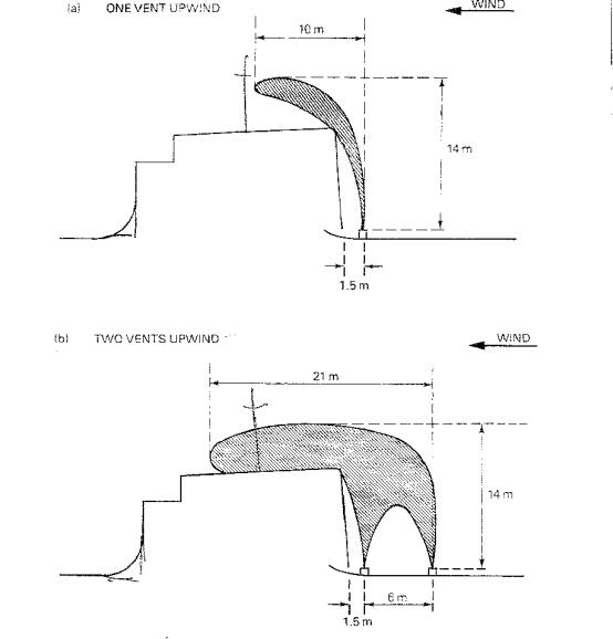
Figure 1.5 Flammable Zones from Apertures near a Deck House
The illustrations above are based upon wind tunnel data of:
Gas mixture: |
50% by volume propane in air |
Diameter of openings: |
152 millimetres |
Wind speed: |
1.1 metres/sec |
Total gas flow per opening: |
1220 cubic metres/hour |
1.4.5MINIMISING HAZARDS FROM VENTED GAS
The objective of venting arrangements and their operational control is to minimise the possibilities of flammable gas concentrations entering enclosed spaces containing sources of ignition or reaching deck areas where, notwithstanding all other precautions, there might be a source of ignition. In previous sections, means have been described of promoting rapid dispersion of gas and minimising its tendency to sink to the deck. Although this section is concerned with flammability, the same principles apply to dispersion of gas down to concentrations that are safe to personnel.
The following conditions are required by SOLAS for any operation where flammable mixtures are displaced to the atmosphere or mixtures are displaced which could become flammable on dilution with air, such as on inerted ships:
•An unimpeded vertical discharge at a high efflux velocity.
•Positioning the outlet sufficiently high above the deck.
•Placing the outlet an adequate distance from the superstructure and other enclosed spaces.
When using a vent outlet of fixed diameter, usually designed for 125% of the maximum cargo loading rate, the efflux velocity will drop at lower loading rates. Vent outlets with automatically variable areas (high velocity vent valve) may be fitted to maintain a high efflux velocity under all loading conditions. The permitted height of the outlet above deck is dependent on whether venting is by a mast riser or through a high velocity vent valve.
The fitted venting arrangements should always be used during loading and ballasting operations.
When gas freeing by fixed mechanical blower, or purging with inert gas either by displacement or dilution through designated outlets, sufficiently high efflux velocities should be maintained to ensure rapid gas dispersion in any conditions.
When gas freeing by portable blowers, it may be necessary to open a tank hatch lid to act as a gas outlet, resulting in a low gas outlet velocity and calling for vigilance to ensure that gas does not accumulate on deck. If an inerted tank is being gas freed through the hatch lid, there may be localised areas where the atmosphere is deficient in oxygen. If practicable, it is preferable to gas free through a small diameter opening, such as a tank cleaning opening, with a temporary standpipe rigged.
In all operations where gas is being vented great vigilance should be exercised, especially under adverse conditions (e.g. if there is little or no wind). Under such conditions, it may be prudent to stop operations until conditions improve.
1.4.6LOADING VERY HIGH VAPOUR PRESSURE CARGOES
1.4.6.1Gas Evolution
This Section has so far dealt with gas evolution and dispersion from high vapour pressure cargoes which give rise to concentrated hydrocarbon gas layers of a depth of 1 metre or less when loaded (see Section 1.4.2.1). Cargoes yielding layers of greater depth are sometimes encountered. The main examples are crude oils, which may have their vapour pressures increased by the addition of extra gas (such as butane) and some natural gasolines, by-products of LNG/LPG production, which are sometimes known as pentanes plus.
Examples of the variation of gas layer depth (to the 50% by volume concentration level) related to true vapour pressure (TVP) are shown in Figure 1.6 for typical natural gasolines and crude oils. There are some cargoes with intermediate properties, for example flash stabilised condensates, some distillation overhead products (which may be shipped as clean petroleum products such as naptha, kerosene or even gas oil) and crude oils with abnormally low methane and ethane contents.
The natural gasoline curve in Figure 1.6 is for a series of blends of different TVPs and the crude oil curve is for a series produced by adding increasing amounts of butane to a crude oil. Below a gas layer depth of about 1 metre, the dependence of depth on TVP is not very marked for either type of cargo. At greater TVPs, it becomes progressively steeper, indicating that in this range a small increase in TVP could cause a very large increase in gas evolution.
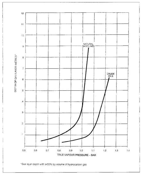
Figure 1.6 Relationship Between Depth of Gas Layer and True Vapour
Pressure.
Boiling commences when the TVP exceeds 1 bar. In the case of the natural gasoline blends this coincides quite closely with the steep increase in gas layer thickness. However, with the crude oil/butane blends the steep increase does not occur until a TVP significantly above 1 bar is reached. Crude oils may be stabilised so that their TVPs are near, or somewhat above, 1 bar as they enter the ship. In practice, therefore, some boiling may occur even without butanisation, but the gas evolution is not necessarily excessive.
In boiling, gas bubbles form below the surface of the liquid, but only down to a depth at which the total pressure (atmospheric plus hydrostatic) is equal to the TVP. The consequent loss of gas in this region may lead to a local fall in TVP. Moreover, the latent heat required to evaporate the gas results in cooling which also reduces the TVP. The
reduction in TVP in the liquid near the surface from both these causes tends to delay boiling, despite the fact that the TVP of the bulk of the liquid is above 1 bar.
That is why crude oils can be handled with their TVPs somewhat above 1 bar. It does not apply to the same extent to the natural gasoline type of product because the gaseous constituents in a crude oil are only a small proportion of the total, whereas a natural gasoline usually consists almost entirely of potentially gaseous compounds. This means that the availability of gas, where boiling is taking place, is far greater with the natural gasolines than with crude oils. Natural gasolines suffer hardly any decrease of TVP due to gas depletion when they begin to boil, and boiling is much more likely to continue in their case than in the case of crude oils.
1.4.6.2Special Precautions with Very High Vapour Pressure Cargoes
When unusually deep gas layers are encountered, very high concentrations of gas, approaching 100% by volume, may be vented for prolonged periods during loading. Excessive amounts of gas may then be present on or around the tanker, which may call for special precautions to be taken.
Curves of the kind given in Figure 1.6 suggest that the TVP at the loading temperature of the cargo should be used as the criterion for determining when special precautions are necessary. The Reid Vapour Pressure of a cargo gives very little guidance unless the temperature of the cargo when loaded is also specified. However, it has proved to be difficult to select TVP criteria because they depend ultimately on subjective judgements of acceptable gas conditions on ships. As a general guide, the available information suggests that consideration should be given to the need for special precautions when the TVP is expected to exceed the following values:
•For natural gasoline type cargoes, for example pentanes plus (C5+), 0.75 bar.
•For crude oils, with or without added gas, 1.0 bar.
•For some intermediate cargoes, for example flash stabilised condensates, some distillation overhead products and crude oils with abnormally low methane and ethane contents, TVP limits between these two values might be appropriate.
Precautions that might then be applied are given in Section 11.1.8.
1.5PYROPHORIC IRON SULPHIDE
1.5.1PYROPHORIC OXIDATION
In an oxygen-free atmosphere where hydrogen sulphide gas is present or, specifically, where the concentration of hydrogen sulphide exceeds that of the oxygen, iron oxide is converted to iron sulphide. When the iron sulphide is subsequently exposed to air, it is oxidised back to iron oxide and either free sulphur or sulphur dioxide gas is formed. This oxidation can be accompanied by the generation of considerable heat so that individual particles may become incandescent. Rapid exothermic oxidation with incandescence is termed pyrophoric oxidation.
Pyrophoric iron sulphide i.e. iron sulphide capable of pyrophoric oxidation in air, can ignite flammable hydrocarbon gas/air mixtures.
1.5.2FORMATION OF PYROPHORS
1.5.2.1General
As described above, the formation of pyrophors is dependent on three factors:
• Presence of iron oxide (rust).
•Presence of hydrogen sulphide gas.
•Lack of oxygen.
However, it also depends on the comparative influence of these factors. The presence of oxygen will inhibit the conversion of iron oxide to iron sulphide. Also, while the concentration of hydrogen sulphide gas has a direct influence on the formation of pyrophors, the degree of porosity of the iron oxide and the rate of flow of the gas over its surface will influence the rate of sulphidation. Experiments have supported the view that there is no safe level of hydrogen sulphide below which a pyrophor cannot be generated.
1.5.2.2In Terminal Operations
In terminal operations, pyrophoric iron sulphide is well recognised as a potential source of ignition. Pyrophoric deposits are apt to accumulate in storage tanks in sour crude service and in process equipment handling sour streams. When such tanks or equipment are taken out of service, it is normal practice to keep all internal surfaces thoroughly wet during ventilation so that there can be no pyrophoric reaction before the equipment is made hydrocarbon gas free.
Deposits and sludge must be kept wet until removed to a safe area where subsequent ignition will cause no damage. Numerous fires have occurred when deposits have dried out prematurely.
1.5.2.3In Marine Operations
While pyrophoric iron sulphide is a widely recognised ignition source in shore-based operations, it has rarely been cited as the cause of a marine ignition and in those few cases the hydrogen sulphide levels were very high. Presumably, marine operations have been free of this hazard because the cargo tanks of non-inerted ships normally contain some oxygen in the vapour space as a result of tank breathing.
However, the use of inert gas on crude carriers may, by decreasing the initial oxygen level as well as that of subsequent replenishments, increase the possibility of forming pyrophoric deposits. Although tanker flue gas normally contains from one to five percent oxygen, this level can be further reduced by absorption into the crude cargo. Furthermore, as the cargo tanks are kept pressurised with inert gas with a low oxygen content no air will enter the ullage space. If the pressure needs to be increased, it will again be done with inert gas having a low oxygen content.
1.5.3PREVENTION OF PYROPHORIC IGNITION IN INERTED CARGO TANKS
As long as the cargo tanks remain inerted, there is no danger of ignition from a pyrophoric exothermic reaction. However, it is imperative that the atmosphere in the tank is not allowed to become flammable. Flammable atmospheres would inevitably arise if the tanks are discharged while the inert gas plant is inoperable.
This does not mean that the probability of ignition is high if discharge without atmospheric control takes place. Various factors may inhibit pyrophor formation or a pyrophoric reaction. These factors include:
•Lack of sufficiently thick deposits of iron oxide.
•Inclusion of elemental sulphur and crude oil in tank deposits.
•Introduction of oxygen by re-pressurising.
These inhibiting factors are not, however, predictable nor can one be confident that they will always be effective. Hence the degree of risk is judged to be high enough to require that atmosphere control is always maintained during and after discharge. To ensure that atmosphere control can be maintained, the following practices should be observed:
• Diligent maintenance of inert gas plants.
•Spares should be kept on hand for critical parts which cannot be obtained quickly or which can fail abruptly (e.g. the fans).
•In the event of an inert gas plant failure prior to or during cargo or ballast discharge, discharge should not commence or continue until the inert gas plant operation is restored, or an alternative source of inert gas is provided.
There is evidence that any pyrophoric deposit formed during the loaded passage will not necessarily be de-activated during the subsequent ballast passage. Therefore, the atmosphere in the tanks should be maintained in an inert or non-flammable condition both throughout the voyage and during the discharge of ballast. The correct application of inert gas and gas-freeing procedures, as described in Sections 7.1 and 11.4, should ensure that a flammable atmosphere is avoided.
1.6THE HAZARDS ASSOCIATED WITH THE HANDLING, STORAGE AND CARRIAGE OF RESIDUAL FUEL OILS
1.6.1GENERAL
Although residual fuel oil normally has a Flashpoint above 60ºC, it is often stored and managed at temperatures close to, or even above, its Flashpoint. High Flashpoint fuels sometimes contain residual quantities of light components that slowly migrate into vapour spaces after loading, so raising the flammability. It must therefore never be assumed that the vapour spaces in, and emissions from, bunker tanks will always be safe simply on account of a high specified Flashpoint. For this reason, ullaging, dipping and sampling procedures must follow the recommendations given in Section 11.7.2.
The first part of this section deals with the flammability hazards associated with residual fuel oils and provides information on Flashpoint and vapour composition measurement, together with recommended precautionary procedures to be adopted when handling, storing or carrying residual fuel oils.
It should be noted that this guidance refers only to residual fuel oils and not distillate fuels.
The second part of this Section refers to the hydrogen sulphide hazard associated with fuel oil. (See also Section 1.2.6 and 1.6.5).
1.6.2NATURE OF HAZARD
Residual fuel oils are capable of producing light hydrocarbons in the tank headspace such that the vapour composition may be near to or within the flammable range. This can occur even when the storage temperature is well below the measured Flashpoint. This is not normally a function of the origin or manufacturing process of the fuel, although fuels containing cracked residues may show a greater tendency to generate light hydrocarbons.
Although light hydrocarbons may be present in the headspaces of residual fuel oil tanks, the risk associated with them is small unless the atmosphere is within the flammable range and an ignition source is present. In such a case an incident could result. It is therefore recommended that residual fuel oil headspaces are regarded as being potentially flammable.
1.6.3FLASHPOINT AND HEADSPACE FLAMMABILITY MEASUREMENT
1.6.3.1Flashpoint
Fuel oils are classified for their safety in storage, handling and transportation by reference to their closed cup Flashpoint. However, information on the relationship between the calculated flammability of a headspace atmosphere and the measured Flashpoint of the
residual fuel oil has shown that there is no fixed correlation. A flammable atmosphere can therefore be produced in a tank headspace even when a residual fuel oil is stored at a temperature below its Flashpoint.
1.6.3.2Headspace Flammability
Traditionally, gas detectors such as explosimeters have been used to check that enclosed spaces are gas free and they are entirely suited to this purpose. They have also been used to measure the “flammability” of headspaces in terms of percentage of the lower flammability limit (LFL). Such detectors rely on a calibration carried out normally on a single hydrocarbon, such as methane, which may have LFL characteristics that are far removed from the hydrocarbons actually present in the headspace. When using an explosimeter to assess the degree of hazard in non-inerted residual fuel oil tank headspaces, it is recommended that the instrument is calibrated with a pentane/air or hexane/air mixture. This will result in a more conservative estimate of the flammability but the readings should still not be regarded as providing a precise measurement of the vapour space condition.
When taking measurements, the manufacturer’s operating instructions for the instrument should be closely followed and the instrument’s calibration should be frequently checked as oxidation catalyst detectors (pellisters) are likely to be susceptible to poisoning when exposed to residual fuel oil vapours.
In view of the problems associated with obtaining accurate measurements of the flammability of residual fuel tank headspaces using readily available portable equipment, the measured % LFL only broadly ranks fuels in terms of relative hazard. Care should therefore be exercised in interpretation of the figures obtained by such gas detectors.
1.6.4PRECAUTIONARY MEASURES
1.6.4.1Storage and Handling Temperatures
When carried as fuel, temperatures of the residual fuel oil in the fuel system should conform to relevant codes of practice at all times and excessive local heating should be avoided.
1.6.4.2Filling and Venting
When tanks are being filled, tank headspace gas will be displaced through vent pipes. Particular care should be taken to ensure that flame screens/traps are in good condition and that there are no ignition sources in the area immediately surrounding the venting system.
When filling empty or near empty tanks, the heating coils should be shut down and cool. Fuel oil contacting hot, exposed heating coils could possibly lead to a flammable atmosphere being rapidly generated.
1.6.4.3Headspace Classification
All residual fuel oil tank headspaces should be classified as “hazardous” and suitable precautions taken. Electrical equipment within the space must meet the appropriate safety standards.
1.6.4.4Hazard Reduction
The flammability of the headspace of residual fuel oil tanks should be monitored regularly.
Should a measured value in excess of recommended levels be detected (IMO Resolution A.565(14) refers to a level in excess of 50% LFL), action should be taken to reduce the vapour concentration by purging the headspace with low pressure air. Gases should be vented to a safe area with no ignition sources in the vicinity of the outlet. On completion of
venting, gas concentrations within the tank should continue to be monitored and further venting undertaken if necessary.
When residual fuel oil is carried as cargo on board tankers fitted with inert gas, it is recommended that the inert gas is utilised and that the headspace is maintained in an inert condition.
1.6.4.5Ullaging and Sampling
All operations should be conducted such as to take due care to avoid the hazards associated with static electrical charges. (See Section 11.7.2).
1.6.5HYDROGEN SULPHIDE HAZARD
Bunker fuels containing high H2S concentrations may be provided by vendors without advice being passed to the ship beforehand. Ship’s personnel should always be aware of
the possible presence of H2S in bunker fuel and be prepared to take suitable precautions if it is experienced.
Before loading bunkers, the ship should communicate with the supplier to ascertain whether the fuel to be loaded is likely to have any H2S content.
The design of bunker tank vents and their location makes managing the exposure to personnel more difficult, as closed loading and venting cannot usually be implemented
If bunkering with fuel containing H2S above the permissible exposure level cannot be avoided, procedures should be in place to monitor and control personnel access to exposure areas.
Ventilation, to lower the concentration of vapour in the ullage space and in specific areas where vapours may accumulate, should be carried out as soon as practical.
The transfer, heating and agitation of the fuel within a tank may cause the concentration to reappear, although the tank may have been previously ventilated to reduce the concentration to an acceptable level.
Periodic monitoring of the concentration of H2S should be continued until the bunker tank is refilled with a fuel not containing H2S. (See Section 1.2.6).