

Учебное пособие 1944
.pdfIssue № 2(30), 2016 |
|
ISSN 2075-0811 |
Fig. 3 shows the d istribution σ̅1 under the effect of a concentrated rolling moment Mz on a structure applied at the end s ection z = l. In the calculations we assume that Mz = 1,57 kN m,0 = 56о, d2 = 0,16 m, l2 = 0,4 25 m. As previously, continuous curves are designed along a short rib with the coordinates x = 2d2, y = –d1/2, the dotted ones along a long one: x = –2d2, y = –d1/2. Dimens onless par ameters of a thin-walled spatial system are shown in Table 2 where d = 4d2/l.
It is clear to see that during rolling of a structure the distribution σ̅1 considerable differs in the short an d long ribs of the slabs.
In all the cases at h̅ 1 we have a gra ph (curve 5) known from the literature [4]. In the section z = 0 there is a clear edge effect due to the restriction of warping o f a skewed section. A surge in strains at h̅= 5 is a t z̅= 0,83. It is obviou sly due to a dramatic decrease in the area of a tra nsverse section of a structure at a large h̅. It is proved b y the fact th at at h̅ 1 there is no mor e surge in s rains in a section z̅= 0,83.
Fig. 4 shows the distribution σ̅1 = f(x̅) in transverse sections of the upper slab corresponding with th coordinat y d1 / 2 , x x / 4d 2 .
Fig. 3 |
Fig. 4 |
For the calculations we assume that l2 = 0,425 m, d̅= 0,25, d̃= 0,4, h̅= 5. The curves 1—4 are designed for a ben ding under a distributed load q(z) at q0 = 24,5 kN/m; the curves 5— 8 — for
21

Scientific Herald of the Voronezh State University of Architecture and Civil Engineering. Construction and Architecture
a bending under a concentrated moment Mz = 1,57 kN m. The curves 1 and 5 correspond with an embedding section (z̅= 0), 2 and 6 are designed at z̅= 0,26, 3 and 7 — at z̅= 0,4, 4 and 8 — at z̅= 0,8.
|
|
|
|
|
|
|
Table 2 |
|
|
|
|
|
|
|
|
Curve |
|
1 |
|
2 |
3 |
4 |
5 |
|
|
|
|
|
|
|
|
d |
|
0,25 |
|
0,5 |
0,25 |
0,25 |
0,25 |
|
|
|
|
|
|
|
|
d |
|
0,4 |
|
0,4 |
0,5 |
0,5 |
0,5 |
h̅ |
|
5 |
|
5 |
5 |
20/7 |
1 |
|
|
|
|
|
|
|
|
In addition a function |
Кp |
a is a sign-alternating continuous row and in PC calculations |
|||||
there is also loss of accuracy, arithmetic disruptions when the row is overfilled or gone. This is what was observed in calculating using formulas containing special functions for h̅= h1/h2 approaching one. This is due to the fact that at h̅ 1 an argument of special functions increases significantly causing inconsistencies in PC calculations. Therefore in order to use PC formulas containing modified functions, it was not the dispersion of these functions into degree rows but their integral representation which is free of disadvantages associated with rows was used.
However the equations describing warping displacements can be integrated using one of the numerical methods, i.e. to solve a linear edge task for second-order differential equations. For that a differential run method was used that helped to solve a number of tasks on PC for a small range of the thickness of embedding and at the free end of the shell (h̅= 1,1). The obtained solutions are in good agreement with solutions for shells with a constant thickness [4]. Besides for h̅≥ 2 displacements and strains determined using numerical integration of warping equations are in agreement with similar values calculated using the formulas containing special functions.
In conclusion it should be noted that cone-shaped thin-walled structures designed along a normal contour of a transverse section or a skewed edge can be examined in an identical fashion. In [7, 8] there are analytical solutions and results of a numerical calculation for a spatial cone-shaped structure of a varying thickness.
Conclusions. The analysis of the graphs shows that in the linear law of changes in the thickness the distribution σ̅1 for h̅= 1,1 ranges identically to a structure with a constant thickness [4]. However, as h̅is on the rise, σ̅1 changes its strain modulus at h = const.
Therefore for the above loading schemes of stress and strain of prismatic thin-walled structures of a constant and variable thickness are different, which should be considered in
22
Issue № 2(30), 2016 |
ISSN 2075-0811 |
calculating elements of actual building structures. By varying the law of changes in the thickness of a structure and thus its stiffness, a new distribution of strains occurring under the effect of different force factors can be obtained.
References
1.Bulatov S. N., Kozlov V. A. K raschetu mnogozamknutykh konstruktsiy peremennoy zhestkosti [Mnogozonnoy to the calculation of constructions with variable rigidity]. AN SSSR. Mashinovedenie, 1987, no. 2, pp. 68—73.
2.Kozlov V. A. Napryazhenno-deformirovannoe sostoyanie mnogosvyaznykh prizmaticheskikh konstruktivnykh elementov mostovykh sooruzheniy [Stress-strain state of a multiply connected prismatic structural elements of bridges. Nauchnyy vestnik Voronezhskogo GASU. Stroitel'stvo i arkhitektura, 2011, no. 4 (24), pp. 110—117.
3.Kozlov V. A. Svobodnye kolebaniya konsol'no zashchemlennykh prizmaticheskikh tonkostennykh konstruktsiy [Free vibrations of console restrained prismatic thin-walled structures]. Nauchnyy vestnik Voronezhskogo GASU. Stroitel'stvo i arkhitektura, 2013, no. 2 (30), pp. 9—17.
4.Obraztsov I. F. Variatsionnye metody rascheta tonkostennykh aviatsionnykh prostranstvennykh konstruktsiy
[Variational methods of calculation of aeronautical thin-walled spatial structures]. Moscow, Mashinostroenie Publ., 1966. 392 p.
5.Obraztsov I. F., Onanov G. G. Stroitel'naya mekhanika skoshennykh tonkostennykh sistem [Building mechanics of thin-walled beveled systems]. Moscow, Mashinostroenie Publ., 1973. 659 p.
6.Kamke E. Spravochnik po obyknovennym differentsial'nym uravneniyam [Handbook of ordinary differential equations]. Moscow, Nauka Publ., 1976. 576 p.
7.Bulatov S. N., Kozlov V. A. Reshenie nekotorykh prikladnykh zadach teorii konicheskikh obolo-chek slozhnoy geometrii [The solution of some applied problems in the theory of conical shells of complex geometry]. RAN. Problemy mashinostroeniya i nadezhnosti mashin, 2000, no. 5, pp. 102—108.
8.Kozlov V. A. [The stress state of noncircular bevel beveled thin-walled structures of variable thickness].
Trudy VIII Vserossiyskoy konferentsii po mekhanike deformiruemogo tverdogo tela [Proc. of the VIII all-Russian conference on mechanics of deformable solids]. Cheboksary, 2014, part 1, pp. 219—222.
9.Kozlov V. A., Bulatov S. N. Stesnennyy izgib s krucheniem konsol'no zashchemlennoy tsilindri-cheskoy obolochki s mnogosvyaznym konturom nekrugovogo ochertaniya [Constrained torsional buckling of a cantilever clamped cylindrical shell with mesh contour noncircular shape]. Nauchnyy vestnik Voronezhskogo GASU. Dorozhno-transportnoe stroitel'stvo, 2004, no. 2, pp. 21—23.
10.Kozlov V. A., Bulatov S. N. Eksperimental'noe issledovanie konicheskikh nekrugovykh zhestko zashchemlennykh sterzhney [Experimental investigation of tapered noncircular rigidly clamped rods]. Nauchnyy vestnik Voronezhskogo GASU. Dorozhno-transportnoe stroitel'stvo, 2004, no. 3, pp. 22—24.
11.Seredin P. V., Glotov A. V., Domashevskaya E. P., Arsentyev I. N., Vinokurov D. A., Tarasov I. S. Structural and optical investigations of AlxGa1−xAs:Si/GaAs(1 0 0) MOCVD heterostructures. Physica B: Condensed Matter, vol. 405, iss. 22, pp. 4607––4614.
12.Mahdy Iman A., Domashevskaya E. P., Seredin P. V., Yatsenko O. B. Spectral features of Co–Ge–Te amorphous thin film. Optics & Laser Technology, vol. 43, iss. 1, pp. 20––24.
23

Scientific Herald of the Voronezh State University of Architecture and Civil Engineering. Construction and Architecture
HEAT AND GAS SUPPLY, VENTILATION, AIR CONDITIONING,
GAS SUPPLY AND ILLUMINATION
UDC 697.973
A. V. Barakov1, N. N. Kozhukhov2, D. A. Prutskikh3, V. Yu. Dubanin4
SIMULATION OF HEAT AND MASS TRANSFER
IN INDIRECT EVAPORATIVE AIR-COOLER
Voronezh State Technical University,
Russia, Voronezh, tel.: (473)243-76-62, e-mail: pt_vstu@mail.ru
1D. Sc. in Engineering, Prof., Head of Dept. of Theoretical and Industrial Heat Power Engineering 2PhD in Engineering, Assoc. Prof. of Dept of Theoretical and Industrial Heat Power Engineering 3PhD in Engineering, Senior Lecturer of Dept of Theoretical and Industrial Heat Power Engineering 4PhD in Engineering, Prof. of Dept of Theoretical and Industrial Heat Power Engineering
Statement of the problem. A way of solving the problem of energy conservation in the design of new and modernization of existing facilities construction is the use of natural temperature gradients in the main and auxiliary equipment of heating, ventilation and air conditioning systems. The concept of indirect evaporative air-cooler with centrifugal fluidized bed of particulate material is developed at the Voronezh State Technical University. A mandatory condition for the effective operation of such devices is the presence of good engineering calculation methods. This necessitated the development and implementation of a mathematical model of heat and mass transfer in the air-cooler.
Results. A mathematical model allowing one to determine the height of a bulk layer, an optimum particle size and the length of the “wet” and “dry” air cooler chambers.
Conclusion. The results of mathematical modeling made it possible to obtain analytical relations for the development of engineering methods of calculating indirect-evaporative air cooler.
Keywords: air cooling, temperature gradient, fluidized bed.
Introduction
One of energy-saving resources is known to be the use of non-traditional energy sources as well as available temperature gradients.
Water evaporative cooling is based on thermodynamic heterogeneity of the atmospheric air which is considered to be the energy for obtaining cold in air conditioning systems of industrial and residential premises.
© Barakov А. V., Kozhukhov N. N., Prutskikh D. А., Dubanin V. Yu., 2016
24

Issue № 2(30), 2016 |
ISSN 2075-0811 |
As theoretical and experimental research suggests [1, 2], passive evaporative air coolers are promising to use with a nozzle with a centrifugal pseudo liquefied layer of a disperse material that circulates due to a dynamic interaction of the major and extra layers of the air [3]. Gas dynamic laws of the formation and movement of this layer have currently been thoroughly studied. Reliable analytical and empirical dependencies have been obtained, which allow one to identify the speed of a liquefied gas [4], speed of the movement of a solid phase [5] and hydraulic resistance of a layer [6].
There have been experimental studies of intensity of an interphase thermal exchange in a pseudo liquefied layer moving through different ducts. The results of these experiments are summed up as empirical criterial ratios [6—8]. In order to introduce this device into wide applications, an engineering calculation method has to be developed. Therefore a mathematical model of thermal mass exchange in a passive evaporative cooler has been designed.
1. Structure of a passive evaporative cooler. The general view of the device is in Fig. 1. It consists of an annular space divided by vertical partitions 1 into “wet” and “dry” areas. In the lower part of the partitions (near a gas distribution grid) there are two windows for unobstructed movement of a nozzle. At the beginning of the “wet” chamber there is a nozzle 2 for wetting the material. Water supply should be controlled so that at the end of the “wet” chamber the nozzle dries completely. The temperature of the nozzle decreases. Its specific value equals the temperature of a wet thermometer. In the “dry” chamber the nozzle heats up providing corresponding cooling of the air.
Fig. 1. Passive evaporative cooler
2. Mathematical modelling of thermal mass exchange. Modelling involves determining major structural and operational parameters of an air cooler: height of a nozzle layer, length of the “wet” and “dry” chambers, initial and final air temperatures in the “dry” and “wet” chambers.
25
Scientific Herald of t he Voronezh State University o f Architecture and Civil Engineering. Construction and Architecture
In solving these problems the following a ssumptions |
were mad e: |
||
|
a te mperature field in wetted and dry particles is |
homogeno us; |
|
|
particles of a layer intensely mix along a vertical keepi |
g their te mperatures constant |
|
along its height. |
|
|
|
2.1. Determining the height of a nozzle layer. Let us conside |
thermal mass exchange in the |
||
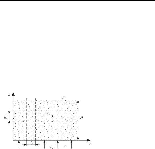
“wet” chamber of he device (Fig. 2). Le us single o ut an element dzdy and design its thermal equilibrium equati on:
св вwвdydtв tн tв fудd zdy , (1) where is a heat capacity; ρ is a densi y; w is a speed; t is a temperatu re; fуд is a specific surface of disperse material ( nozzle); α is a heat emission coefficient; the indices в, н are the air and nozzle respectively.
Fig. 2. Calculation scheme
Dividing the varia bles and integrating |
the |
equatio ns |
(1) und er the |
initial conditio n z = 0, |
||||
tв = t'в e get: |
|
|
|
|
|
|
|
|
|
|
|
|
f |
уд |
|
|
|
tв tн |
tв |
- tн exp |
|
|
z . |
(2) |
||
св вwв |
||||||||
|
|
|
|
|
|
|||
The air temperature as it leaves the layer is obtaine from (2) a t z = H and |
a necessary height |
of the nozzle layer is identified based on thermal exc hange having to be complete: |
|
H 2,3 cв вwв . |
(3) |
fуд |
|
Consid ring that a specific su face of a d sperse material is given by the formula [3]
fуд |
6 1 |
, |
|
||
|
dэ |
|
26

Issue № 2(30), 2016 |
|
|
|
|
|
ISSN 2075-0811 |
|
and а protruding height of the layer is calculated again using the following ratio |
|
||||||
H0 |
H |
1 |
, |
|
|
||
|
|
|
|
||||
|
1 0 |
|
|
||||
finally we get: |
|
|
|
|
|
|
|
H0 |
13,8 |
cв вwвdэ |
, |
(4) |
|||
1 0 |
|||||||
|
|
|
|
|
|||
where dэ is an equivalent diameter of the nozzle particles; ε is porosity of a centifugal pseudo liquefied layer; ε0 is protruding porosity of a disperse material.
For a coefficient of heat emission which are typical of a centrifugal pseudo liquefied
layer (α = 400…800 |
Watt/(m2·К)) and |
for optimal sizes of |
a |
disperse |
material |
particle |
(dэ = 1…4 mm) a |
protruding height |
of a nozzle layer |
in |
an air |
cooler |
will be |
H0 = 20…60 mm. It should be noted that the height of a nozzle layer determined based on mass exchange having to be complete in the “wet” chamber of the device is almost identical with the result obtained by means of the equation (4).
2.2. Length of the “wet” chamber of the device. In order to determine the temperatures of the nozzle tн using the coordinate y let us write the equation of a heat balance for the element Hdy (Fig. 2):
cнGнdtн cвrвwв tв - tв bdy rвwв x - x brпdy, |
(5) |
where Gн is mass consumption of the nozzle; b is the width of the chamber of the device; x' and x'' is the moisture content of the air at the inlet and outlet of the device; rп is latent heat of vapour.
The moisture content at the inlet and outlet of the “wet” chamber can be expressed using corresponding partial pressures of water vapour using the formula [1]
x 0,622 |
Pп |
, |
(6) |
|
|||
|
P |
|
|
where Рп is the partial pressure of water vapor in the air; Р is the total air pressure. The partial pressure of water vapor in any transverse section of the layer is [1]
|
|
|
f уд P |
|
|
|
|
||
Pп Pпw Pп Pпw exp |
|
|
|
|
|
z |
, |
(7) |
|
|
|
|
|
||||||
0 |
,622 в wв RпT |
||||||||
|
|
|
|
|
|
||||
where Рпw is partial pressure of vapor at the surface of the particles; β is a coefficient of mass transfer from the air to the surface of the particles; Rп is a gas constant of vapor; T is an average absolute of the air temperature.
27

Scientific Herald of the Voronezh State University of Architecture and Civil Engineering. Construction and Architecture
The dependence of a partial pressure of vapor at the surface of the particles Рпw absolute temperature of the particle Tн is given by the ratio [9, 10]
P |
P |
|
|
|
|
|
|
|
|
, |
|
1 |
rп |
Tн -Tнас |
|
||||||||
|
|
|
|
|
|
||||||
пw |
п |
|
|
Rп |
|
|
T |
|
2 |
|
|
|
|
|
|
|
|
нас |
|
|
|
||
on the
(8)
where T'нас is the temperature of saturation of vapor for a partial pressure of vapor Р'п. After inserting (6), (7) and (8) into (5) and integrating under the initial condition y = 0, tн = T'н we get:
|
|
|
|
|
|
|
|
|
|
|
|
|
|
|
|
|
|
|
|
|
|
|
|
|
|
|
|
|
|
|
|
|
|
|
|
|
|
|
|
|
t |
|
|
|
A1tв |
|
|
A2tнас |
|
|
|
t |
|
|
|
|
|
A1tв |
|
|
A2tнас |
|
|
|
exp A A |
y , |
(9) |
||||||||||||||
|
|
|
|
|
|
|
|
|
|
|
|
|
|
|||||||||||||||||||||||||||
|
н |
|
A |
|
A |
A |
|
A |
|
н |
|
A |
|
A |
|
|
A |
A |
|
|
|
|
1 2 |
|
|
|||||||||||||||
|
|
|
|
1 |
|
2 |
|
|
1 |
|
2 |
|
|
|
|
|
|
|
|
1 |
|
|
2 |
|
|
|
1 |
|
|
2 |
|
|
|
|
|
|
|
|
||
|
|
|
|
|
|
A1 |
|
|
|
c w b |
|
|
|
|
|
|
|
|
|
|
|
|
|
f |
удH |
, |
|
|
|
|||||||||||
|
|
|
|
|
|
|
|
|
в |
в |
в |
|
|
|
|
|
|
1 |
exp |
|
|
|
|
|
|
|
|
|
||||||||||||
|
|
|
|
|
|
|
|
|
|
|
|
|
|
|
|
|
|
|
|
|
|
|
|
|
|
|
|
|
|
|
|
|
|
|
|
|||||
|
|
|
|
|
|
|
|
|
|
c G PR T |
|
2 |
|
|
|
|
|
|
|
|
|
|
cв вwв |
|
|
|
|
|
||||||||||||
|
|
|
|
|
|
|
|
|
|
н |
н |
п |
|
нас |
|
|
|
|
|
|
|
|
|
|
|
|
|
|
|
|
|
|
|
|
|
|||||
|
|
|
|
|
|
|
|
|
|
|
w br2 P |
|
|
|
|
|
|
|
|
|
|
|
|
|
fудH |
|
|
|
|
|||||||||||
|
|
A2 |
0,622 |
|
|
|
в |
в |
|
п |
п |
|
|
|
|
1 |
exp |
|
|
|
|
|
|
|
|
. |
|
|
||||||||||||
|
|
|
c G PR |
|
T |
2 |
|
0,622 вwв RпT |
|
|
||||||||||||||||||||||||||||||
|
|
|
|
|
|
|
|
|
|
|
|
|
|
|
|
|
|
|
|
|||||||||||||||||||||
|
|
|
|
|
|
|
|
|
|
н |
н |
|
п |
нас |
|
|
|
|
|
|
|
|
|
|
|
|
|
|
|
|
|
|
|
|
||||||
From the physical ratios we conclude that at y → ∞ the temperature of the nozzle equals that of a wet thermometer and thus based on (9) we get:
tм |
A1tв |
|
A2tм |
, |
(10) |
A1 A2 |
|
||||
|
|
A1 A2 |
|
||
where tм is the temperature of a wet thermometer. Specifying the ratio
tн - tм 0,1 tн - tм
using a combination of solutions for (9) and (10), we find a necessary length of the “wet” chamber:
L |
|
|
2,3 |
. |
(11) |
|
|
||||
м |
|
A1 |
A2 |
|
|
|
|
|
|||
2.3. Length of the “wet” chamber of the device. Calculation ratios for the “wet” chamber it can be obtained using corresponding formulas for the “wet” chamber assuming that a coefficient of mass transfer β = 0.
Then based on (9) we get:
tм tв tм |
tв exp A1 y , |
(12) |
||
and based on (11): |
|
|
|
|
Lм |
2,3 |
. |
(12') |
|
|
||||
|
|
A |
|
|
|
|
1 |
|
|
28
Issue № 2(30), 2016 |
ISSN 2075-0811 |
The temperature of a nozzle at the outlet of the “wet” chamber is determined according to (12) by inserting y = Lc and a heat flow diverted from the air to the nozzle in the “wet” chamber:
н н в |
н |
exp |
|
1 с |
(13) |
|
Q c G |
t t 1 |
|
A L . |
|||
Then the air temperature at the outlet of the “wet” chamber equals
tв tв |
Q |
. |
(14) |
|
cв вwвb |
||||
|
|
|
Conclusions
1.A mathematical model of thermal and mass transfer in a moving pseudo liquefied layer of a complex disperse material.
2.As a result of implementing the model the analytical dependencies were first obtained allowing one to determine “protruding” height of a dispersed material, a necessary length of the “wet” and “dry” chambers of air coolers and air temperature at the outlet of the “wet” chamber.
3.The obtained analytical ratios are a scientific base for developing engineering methods of calculating a passive evaporative cooler with a dispersed nozzle.
References
1.Kokorin O. Ya. Isparitel'noe okhlazhdenie dlya tseley konditsionirovaniya vozdukha [Evaporative cooling for the purpose of air conditioning]. Moscow, Stroyizdat Publ., 1965. 159 p.
2.Barakov A. V., Dubanin V. Yu., Prutskikh D. A., Naumov A. M. Issledovanie vozdukhookhladitelya kosvenno-isparitel'nogo tipa s dispersnoy nasadkoy [The study of air-cooler of indirect-evaporation type with disperse nozzle]. Promyshlennaya energetika, 2010, no. 11, pp. 37—40.
3.Gel'perin N. I., Aynshteyn V. G., Kvasha V. V. Osnovy tekhniki psevdoozhizheniya [Basic techniques of fluidization]. Moscow, Khimiya Publ., 1967. 664 p.
4.Barakov A. V., Dubanin V. Yu., Prutskikh D. A. Issledovanie gidrodinamiki regeneratora s dis-persnoy nasadkoy [Study of hydrodynamics of the regenerator with disperse nozzle]. Energosberezhenie i vodopodgotovka, 2009, no. 1, pp. 47—48.
5.Agapov Yu. N., Barakov A. V., Zhuchkov A. V. Issledovanie dvizheniya psevdoozhizhennogo sloya vdol' naklonnoy gazoraspredelitel'noy reshetki [The study of motion along an inclined fluidized bed of the gas distribution grid]. Teoreticheskie osnovy khimicheskoy tekhnologii, 1986, vol. 20, no. 1, pp. 111—115.
6.Agapov Yu. N., Barakov A. V., Zhuchkov A. V., Sannikov A. V. Otsenka gidravlicheskogo soprotivle-niya i mezhfaznogo teploobmena v tsentrobezhnom psevdoozhizhennom sloe [Evaluation of hydraulic resistance and interfacial heat transfer in a centrifugal fluidized bed]. Khimicheskaya promyshlenost', 1986, no. 4, p. 61.
7.Faleev V. V., Barakov R. A. Eksperimental'noe issledovanie gidrodinamiki i teploobmena v peremeshchayushchemsya psevdoozhizhennom sloe [Experimental investigation of hydrodynamics and heat transfer in a moving fluidized bed]. Vestnik Voronezh. gos. tekhn. un-ta. Energetika, 2001, iss. 1, pp. 28—31.
8.Protsenko V. P., Barakov A. V., Sannikov A. V. Utilizator teploty s peremeshchayushchimsya teplonositelem [The heat recovery from the moving coolant]. Tekhnika v sel'skom khozyaystve, 1988, no. 2, pp. 11—12.
9.Kirillin V. A., Sychev V. V., Sheyndlin A. E. Tekhnicheskaya termodinamika [Engineering thermodynamics]. Moskow, MEI Publ., 2008. 496 p.
10.Rivkin S. L., Aleksandrov A. A. Termodinamicheskie svoystva vody i vodyanogo para [Thermodynamic properties of water and steam]. Moskow, 1984. 80 p.
29

Scientific Herald of the Voronezh State University of Architecture and Civil Engineering. Construction and Architecture
DESIGNING AND CONSTRUCTION OF ROADS, SUBWAYS,
AIRFIELDS, BRIDGES AND TRANSPORT TUNNELS
UDC 625.731:625.76
F. V. Matvienko1, O. V. Ryabova2, S. N. Kuznetsov3
IMPROVEMENT OF THE METHODS OF SELECTION OF THE COMPOSITION OF SOILS AND ROAD PAVING MATERIALS REINFORCED
WITH CEMENT IN MAINTAINING ROADS
Voronezh State University of Architecture and Civil Engineering Russia, Voronezh, tel.: +7-980-538-11-02, e-mail: fmatvienko@yandex.ru
1PhD in Engineering, Assoc. Prof. of Dept. of Construction and Operation of Highways 2D. Sc. in Engineering, Prof. of Dept. of Construction and Operation of Highways
3D. Sc. in Engineering, Assoc. Prof. of Dept. of Heat and Gas Supply and Oil and Gas Business
Statement of the problem. Currently the regulations governing the means and methods of selection of the composition of soils and materials road pavements, reinforced with cement include a number of contradictions and provisions requiring specification concerning the required physical and mechanical characteristics of a structural layer.
Results. The paper presents the rationale for the need to clarify the costs of cement, depending on the number of reasons that can lead to unattainable results by grade strength on the production from laboratory results of selection of the composition of the material (soil) strengthened with cement.
Conclusions. In choosing cement it is not only the minimum values of the likeness for a particular brand but also its optimal value taking into account reserve strength factor that should be important. The sequence of input components of a cementogenesis mixture, mixing time and required breaks between operations in the preparation of a mixture in the laboratory should be as close as possible to production. When preparing samples in the laboratory load at molding samples, the maximum density should be provided and it is also necessary to control the coefficient of consolidation of a structural layer of cement enamel material.
Keywords: road maintenance, road construction, strengthened material, cement and mineral mix, ground-cement mixture, strength.
© Matvienko F. V., Ryabovа О. V., Kuznetsov S. N., 2016
30