

Учебное пособие 1944
.pdfIssue № 2(30), 2016 |
ISSN 2075-0811 |
maximum external load on a specimen cracks of a normal breakaway lсv reach their maximum and shear cracks lсv continue to grow intensely.
Due to failure of concrete and crack formation, it is necessary to consider this process in terms of energy and emission of some of in sound waves. As characteristics of sound waves are associated with formation of cracks [9], there has to be a mathematical model of propagation of these waves for them to be recorded.
Let us look into propagation of acoustic (sound) waves in a cement concrete structure – not restricted, elastic, saturated with gas or liquid porous medium. Physical and mechanical properties of a medium are specified with a complex elasticity modulus.
2. Mathematical model of damping of elastic waves caused by acoustic emission during their propagation in cement concrete structures. Formation of cracks is a spatial statistical process of defects of a material resulting in sound waves propagated along different trajectories of a continuous medium which is commonly a porous material.
Dynamic deformation of such a porous medium is described with a system of equations [10— 13]:
2u(1)j
xi x j
|
|
|
2u(1)j |
|
|
2u(1) |
|
R |
|
2u(j |
2) |
|
2u(1) |
|||||||||
|
|
|
|
|
|
|
|
|
|
i |
|
|
|
|
|
|
i |
|||||
|
|
x |
|
x |
|
|
|
|
|
x |
x |
|
||||||||||
|
|
|
|
i |
j |
|
|
x2 |
|
|
|
j |
11 t2 |
|||||||||
|
|
|
|
|
|
|
|
|
|
j |
|
|
|
i |
|
|
|
|
||||
R |
|
|
2u |
(1)j |
|
|
Q |
|
2u(2)j |
|
2u |
(1) |
|
2u(2) |
||||||||
|
|
|
|
|
|
|
|
|
|
|
|
|
|
|
i |
|
i |
|||||
|
|
x |
x |
|
|
|
|
x x |
|
|
|
|
||||||||||
|
|
|
j |
|
|
j |
|
12 t2 |
|
|
22 t2 |
|||||||||||
|
|
|
|
i |
|
|
|
|
|
i |
|
|
|
|
|
|
|
|
||||
11 1 12 , |
22 2 12 , |
11 22 |
||||||||||||||||||||
|
2u(2) |
0, |
i |
||
12 |
t2 |
|
0, |
|
(7) |
2 12 , |
|
|
where ui( x) (x 1, 2) are components of a displacement vectors of phases; , , R ,Q are complex moduluses of elasticity of the first and second phase in a volume unit of a medium; α1 and α2 characterize proportions of a volume of a mix occupied by each phase (α1 + α2 = 1, α1 > 0, α2 > 0).
The solution of the system is presented by an attenuating wave [11—12]:
u( |
) C( |
) exp(i t x |
k |
) , i , с, 1, 2 , |
(8) |
j |
j |
k |
|
|
where Cj(χ) is an oscillation amplitude; vi are coordinates of a unit vector in direction of a wave propagation speed; c > 0 is a wave speed; α > 0 is a coefficient of damping of a wave; ω is an angular frequency; β is a phase constant.
Inserting (8) into (7), we get a system of two equations:
( C(1)j i j C(1)j i j Ci(1) )( i )2 R ( i )2 C(2)j i j 11 2Ci(1) 12 2Ci(2) 0, (9) R ( i )2 C(1)j i j Q ( i )2 C(2)j i j 12 2Ci(1) 22 2Ci(2) 0.
11

Scientific Herald of the Voronezh State University of Architecture and Civil Engineering. Construction and Architecture
Characteristics of longitudinal waves are determined if we assume that C( ) |
i |
0 |
( 1, 2) , |
i |
|
|
α = αl, β = βl. Let us multiply equations (9) by vi and sum them using a repetitive index i. Using a system (9) we get a biquadratic equation in relation to αl + iβl:
( |
|
2 )( |
l |
i |
)4 |
( |
11 |
|
|
|
2 |
|
) 2 |
( |
l |
i |
)2 |
( |
11 |
|
12 |
2 |
) 4 |
0 , (10) |
11 |
22 |
12 |
l |
|
|
22 |
|
22 11 |
|
12 12 |
l |
|
l |
|
|
|
12 |
l |
|
|
|
l Gl , Gl |
H , |
|
|
|
|
|
where |
2 , |
|
H , |
|
R |
H , |
|
|
|
|
11 |
|
12 |
|
|
|
|
|
Q H , |
H Q 2R , |
i |
, |
||||
22 |
|
1 |
1 |
1 |
|
1 |
2 |
|
11 11  , 12 12
  , 22 22
are dimensionless complex coefficients; G l , l is a speed of propagation of a longitudinal wave and a phase constant when the coefficients of a porous medium are real numbers.
For the solution of a phase task to meet the equations of elastic propagation with damping the following must hold true
|
|
|
|
|
2 |
|
11 |
|
22 |
|
2 |
12 |
1. |
|
|
|
|
|||||||||
|
|
|
11 |
|
22 |
|
|
12 |
|
|
|
|
|
|
|
|
|
|
|
|
|
|
||||
A biquadratic equation (10) is solved in relation to a real |
|
l2 l2 |
and imaginary ( l l ) |
|||||||||||||||||||||||
parts: |
|
|
|
|
|
|
|
|
|
|
|
|
|
|
|
|
|
|
|
|
|
|
|
|
|
|
|
|
2 |
2 |
2kb 2 |
(b2 b2 ) , |
|
l |
|
l |
kb 2 |
(b2 |
b2 ) , |
|
(11) |
||||||||||||
|
|
l |
l |
|
|
1 |
l |
|
1 |
|
2 |
|
|
|
|
|
|
2 |
l |
1 |
|
2 |
|
|
||
|
|
|
k |
22 |
2 |
, |
b Г |
r cos( |
2) |
, |
|
|
|
|
||||||||||||
|
|
|
|
11 |
|
12 |
|
1 |
|
1 |
|
|
|
|
|
|
|
|
1 |
|
|
|
|
|
|
|
|
b Г |
r sin( |
2) |
, |
Г |
|
|
22 |
|
2 |
, |
|
|
|||||||||||||
|
2 |
|
2 |
|
|
1 |
|
1 |
|
11 |
22 |
|
|
|
|
|
11 |
|
12 |
12 |
|
|
|
|||
|
|
|
|
|
|
|
|
|
|
|
|
|
|
|
|
|
|
|
|
|
|
|
||||
|
|
Г2 11 22 22 11 2 12 12 , 11 |
11 i 11 , |
|
|
|
|
|||||||||||||||||||
|
|
|
|
|
|
|
|
|
|
|
|
|
|
|
|
|
|
|
|
|
|
|
|
|
||
|
|
12 |
12 i 12 , 22 |
22 i 22 , r |
|
1 |
2 |
, |
|
|
|
|||||||||||||||
2 |
2 |
4kE1 , 2 2(Г1 Г2 2kE2 ) , |
|
|
|
|
|
|
|
|
|
|
|
|
2 |
2 |
, |
|||||||||
1 Г1 |
Г2 |
E1 11 22 11 22 |
12 |
12 |
||||||||||||||||||||||
E2 11 22 11 22 2 12 12 , tg 1 2  1 , 0 1
  2 .
2 .
Using (11) we find a coefficient of damping of a longitudinal wave and a phase constant:
|
|
|
|
|
kb |
2 |
2 |
|
|
|
|
|
|
k 2 |
(b b2 |
b2 ) |
|
|
|
|
l |
|
|
|
2 |
l |
|
|
, |
|
l |
|
l |
1 |
1 |
2 |
. |
(12) |
|
|
|
(b2 |
b2 )(b |
|
b2 |
b2 ) |
|
|
|
b12 b22 |
|
|
|
||||||
|
|
1 |
2 |
1 |
|
|
1 |
2 |
|
|
|
|
|
|
|
|
|
|
|
12
Issue № 2(30), 2016 |
ISSN 2075-0811 |
Considering that for a longitudinal wave a phase constant l  cl and coefficient characterizing a propagation medium of an elastic wave are complex numbers, we find a propagation speed of a longitudinal wave:
c |
l |
|
G 2 |
(b 2 |
b 2 ) |
k (b |
b 2 |
b 2 |
) . |
|
|
l |
1 |
2 |
1 |
1 |
2 |
|
In an elastic porous medium saturated with gas there are two types of longitudinal waves as b1
and b |
have a « » sign. Given |
that |
|
1 b |
|
b 2 |
is a propagation speed, coefficient of |
||||||||||||||||||||||||||||
2 |
|
|
|
|
|
|
|
|
1 |
|
|
|
|
|
|
2 |
|
1 |
|
|
|
|
|
|
|
|
|
|
|
|
|
|
|
||
damping of waves and phase constants are the following: |
|
|
|
|
|
|
|
|
|
|
|
||||||||||||||||||||||||
|
l1,2 |
|
|
k 2 ( 1) |
, |
l1,2 |
|
|
k 2 ( 1) |
, cl1,2 |
|
|
|
b1Gl2 12 |
(13) |
||||||||||||||||||||
|
|
|
b G 2 2 |
|
|
|
|
b G 2 2 |
|
|
|
|
k( 1) , |
||||||||||||||||||||||
|
|
|
|
|
|
1 |
|
|
|
|
|
|
|
|
|
|
|
|
|
|
1 |
|
|
|
|
|
|
|
|
|
|
|
|
||
|
|
|
|
|
1 |
l 1 |
|
|
|
|
|
|
|
|
|
|
|
1 |
|
|
l 1 |
|
|
|
|
|
|
1 |
|
|
|
||||
|
|
G |
H |
|
|
1 |
Q1 |
|
2R1 |
|
|
1 |
2 1 Q1 |
2R1 |
. |
(14) |
|||||||||||||||||||
|
|
|
|
|
|
|
|
|
|
|
|
|
|
|
|
|
|
|
|
|
|
|
|||||||||||||
|
|
l |
|
|
|
|
|
|
|
|
|
|
|
|
|
|
|
|
|
|
|
|
|
|
|
|
|
|
|
|
|
|
|||
|
|
|
|
|
|
|
|
|
|
|
|
|
|
|
|
|
|
|
|
|
|
|
|
|
|
|
|
|
|
||||||
Using the formulas for R1, Q1, λ1, μ1 from [11, 14—15] and the expression for Gl, we get |
|
||||||||||||||||||||||||||||||||||
|
|
|
l |
|
|
|
|
|
( 2 ) 2 |
( 1) |
|
|
, |
|
|
|
|
|
|||||||||||||||||
|
|
|
|
|
|
|
|
|
|
11 |
22 |
|
|
12 |
|
|
|
1 |
|
|
|
|
|
|
|
|
|
|
|||||||
|
|
|
|
|
|
|
|
|
|
|
|
|
|
|
|
|
|
|
|
|
|
|
|
|
|
|
|
|
|||||||
|
|
|
1,2 |
|
|
|
2 |
|
E(1 ) |
|
|
|
|
|
|
|
|
|
|
|
|
|
|
|
|||||||||||
|
|
|
|
|
|
|
|
b1 1 |
|
|
|
|
|
|
|
|
|
|
|
R0 |
(2 m) |
|
|
|
|
|
|
||||||||
|
|
|
|
|
|
|
|
|
|
|
|
|
|
|
|
|
|
|
|
|
|
|
|||||||||||||
|
|
|
|
|
|
|
|
|
|
(1 )(1 2 ) |
|
|
|
|
|
|
|
|
|
|
|
|
|||||||||||||
|
|
|
|
|
|
2 |
|
|
|
E(1 |
) |
|
|
|
|
|
|
|
|
|
|
|
|
|
|
|
|||||||||
|
|
|
|
|
|
|
b1 1 |
|
|
|
|
|
|
|
|
|
|
|
R0 (2 m) |
|
|
|
|
|
|
(15) |
|||||||||
|
|
|
|
|
|
(1 )(1 2 ) |
|
|
|
|
|
||||||||||||||||||||||||
|
|
|
c |
|
|
|
|
|
|
|
|
|
|
|
|
|
, |
|
|
|
|
|
|||||||||||||
|
|
|
|
|
|
|
|
( |
|
|
2 |
)( 1) |
|
|
|
|
|
|
|
||||||||||||||||
|
|
|
l1,2 |
|
|
|
|
|
|
22 |
|
|
|
|
|
|
|
|
|
||||||||||||||||
|
|
|
|
|
|
|
|
|
|
|
|
|
11 |
|
|
|
12 |
|
|
|
1 |
|
|
|
|
|
|
|
|
|
|
|
|
||
where m is porosity of a medium; R0 is a compressibility of a gas (air); v is the Poisson coefficient; E is Young’s modulus; k ( 11 22 122 ) .
Coefficients of damping and propagation speed of acoustic waves in the formulas (15) are presented in detail. Here b1 and η1 are calculated using variables Г1, Г2, Е1, Е2 which are determined as follows:
Г1 11Q1 22 ( 1 |
2 1 ) 2 12 R1 , Г2 |
11Q2 |
22 ( 2 2 2 ) 2 12 R2 , (16) |
|||||||
E ( 2 )Q ( |
2 |
2 |
2 |
)Q R2 |
R2 |
, |
||||
1 |
1 |
1 |
1 |
|
2 |
1 |
2 |
|
||
E2 ( 1 2 1 )Q2 ( 2 2 2 )Q1 2R1R2 .
The characteristics of a transverse wave are identified using (3) if we assume that C(j ) j 0
( 1, 2) and move on to the dimensionless coefficients:
|
2 |
|
|
( t i t ) |
2 |
(1) |
2 |
2 |
0 , |
(17) |
|
11 t |
|
Ci |
12 t |
Ci |
|||||
13
Scientific Herald of the Voronezh State University of Architecture and Civil Engineering. Construction and Architecture
|
|
|
|
|
|
|
|
|
C(1) |
C(2) |
0, |
|
|
|
|
|
|
|
|
|||||
|
|
|
|
|
|
|
|
|
12 |
i |
|
22 |
i |
|
|
|
|
|
|
|
|
|
||
where t Gt |
|
and Gt |
|
H 11 |
|
|
H 1 is the speed of a transverse wave at |
2 = 0, |
||||||||||||||||
H 1 . |
|
|
|
|
|
|
|
|
|
|
|
|
|
|
|
|
|
|
|
|
|
|
|
|
Given that 2 |
|
|
1 2 |
1 2 |
we get the following ratios: |
|
|
|
|
|
|
|
||||||||||||
|
t |
|
k 2 ( 1) |
|
k 2 ( 1) |
, t |
|
k 2 ( 1) |
|
k 2 ( 1) |
(18) |
|||||||||||||
|
2 |
|
2 |
|
2 |
|
G2 |
2 |
|
2 |
2 |
2 |
G2 2 |
. |
||||||||||
|
|
|
|
t |
|
2 |
|
|
|
|
2 |
|
|
|
|
t |
2 |
|
|
2 |
|
|
|
|
|
|
|
|
|
22 2 |
1 |
|
|
22 t |
2 |
1 |
|
|
|
|
22 2 1 |
|
|
22 t 2 |
1 |
|
|
||
The speed of a transverse wave is determined knowing that t  сt :
сt :
c |
2 |
2 2 |
|
2 |
2 G2 |
|
|
|
22 |
2 1 |
|
22 2 1 t . |
(19) |
||
k 2 1 |
|
||||||
t |
|
k 1 |
|
||||
|
|
t |
2 |
|
|
2 |
|
Let us write the formulas (18) and (19) in detail considering physical and mechanical properties of a medium:
|
11 22 122 11 2 2 1 |
|
|
11 22 122 11 2 2 |
1 2 1 |
2 |
|||||||||||||||||
t |
|
2 |
|
2 |
2 |
|
|
|
|
|
|
|
|
|
|
|
|
|
|
, (20) |
|||
|
22 |
|
|
|
|
|
|
|
|
|
22 |
2 Е2 |
|
|
|||||||||
|
|
|
|
2 |
1 |
|
|
|
|
|
|
|
|
|
|
|
2 |
|
|
|
|
||
ct |
11 22 |
2 2 2 |
|
|
|
|
|
11 22 |
|
2 Е2 |
|
1 2 . |
|||||||||||
122 |
11 2 1 |
|
122 11 |
2 1 2 |
|||||||||||||||||||
|
|
22 |
|
2 |
1 |
|
|
|
|
|
|
|
|
|
|
22 |
2 |
|
|
|
|
|
|
A logarithmic decrement of oscillations of a wave is |
|
|
|
|
|
|
|
|
|
|
|||||||||||||
|
|
tg |
2 |
2 |
t t |
|
|
2 |
t ct |
|
, |
|
(21) |
||||||||||
|
|
2 |
|
2 |
2 ( c )2 |
|
|||||||||||||||||
|
|
|
|
|
|
|
|
|
|
|
|
|
|
|
|
||||||||
|
|
|
|
|
|
|
|
|
|
t |
|
|
t |
|
|
|
|
t |
t |
|
|
|
|
where tg 2 is a tangent of an angle of mechanical losses:
tg 2 |
|
JmM |
|
2 |
|
t |
|
||
|
|
|
|
t |
|
. |
|||
Re M |
t2 |
t2 |
|||||||
|
|
|
|
||||||
A logarithmic decrement of oscillations of a transverse wave in a porous medium depends on a coefficient of damping of a wave and the speed of a wave passing through a signal source (crack) to the device.
Based on the expressions (15), (21), coefficients of damping and propagation speed of longitudinal and transverse elastic waves of acoustic emission depend on the Poisson’s coefficient v, Young’s modulus Е, porosity m, density ρ and mass of the components of a medium, i.e. characteristics and properties of a material.
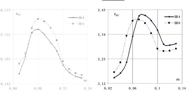
Fig. 2—3 show dependencies of a coefficient of damping and propagation speed of a longitudinal elastic acoustic wave on the porosity of cement concrete.
14
Issue № 2(30), 2016 |
|
|
ISSN 2075-0811 |
|
|
|
|
|
|
Fig. 2. Dependence of a coefficient of damping |
Fig. 3. Dependence of the propagation peed |
of an elastic longitudi nal acoustic w ave on the po rosity |
of an elasti acoustic wa ve on the poro sity |
of cement concrete |
of cement co ncrete |
It is obvious that growing damping is caused by dislocations transformi ng into a new state [16] and the spee d decreasing in this porosity range characte rizing stationary processes of elastic interaction.
This can be used |
s a criterio n of thresh old porosity of a medium as well as in pre dicting a |
resource of cement concrete pavements. |
|
Conclusions |
|
1. Deve lopment of |
technologies of determining the concrete p arameters using acou tic non- |
restrictive method |
of control focus on the paramet ers of the porosity of a medium o f elastic |
wave pr opagation.
2. Determining cr ack resistan ce using acoustic emission is d e to physical and mechanical parameters of a medium of pr opagation of sound waves being necessary to identify as well.
3. Determining th speed and |
damping |
of sound waves in ce ment concr ete can be used not |
only in identifying porosity bu t also in predicting cr ck formati on. |
||
4. The obtained mathematical |
model of |
dissipative processes (formation o f cracks) occurring |
during harmonic e xcitation of elastic por ous media s aturated w th gas excited by soun d waves specified by complex number s allows mo re accurate prediction of crack resistance of concrete
materials. The formulas for |
determining |
propagation speeds of longitudinal and transverse |
||
sound |
waves, coefficients of |
damping |
and logarithmic decrement of o scillation |
damping |
which |
are expressed by the |
characteristics of a medium: the Poisson coefficient, |
Young’s |
|
modulus, porosity, compressi bility and d ensity of gas.
15

Scientific Herald of the Voronezh State University of Architecture and Civil Engineering. Construction and Architecture
References
1.Odnokol'tsev A. V., Vlasov A. I., Rutkevich A. V. Sistema nerazrushayushchego kontrolya na osnove yavleniya akusticheskoy emissii [Destructive testing system based on acoustic emission]. Inzhenernyy vestnik, 2012, no. 8, pp. 1—19. Available at: http://engbul.bmstu.ru/doc/478936.html
2.Ekobori T. Fizika i mekhanika razrusheniya i prochnosti tverdykh tel [Physics and mechanics of fracture and strength of solids]. Moscow, Metallurgiya Publ., 2012. 263 p.
3.Irvin D. R. Analiz napryazheniy i deformatsiy, voznikayushchikh na krayu treshchiny, peresekayu-shchey plastinu [Analysis of stresses and deformations occurring at the edge of a crack traversing a plate]. Teoreticheskaya mekhanika, 1957, vol. 24, no. 3, pp. 361—364.
4.Cherepanov G. P. Mekhanika khrupkogo razrusheniya [Mechanics of brittle fracture]. Moscow, Nauka Publ., 1974. 640 p.
5.Piradov K. A., Guzeev E. A., Mamaev T. L., Abdullaev K. U. Opredelenie kriticheskogo koef-fitsienta intensivnosti napryazheniy betona i zhelezobetona pri poperechnom sdvige [Determination of critical stress intensity factor of concrete and reinforced concrete while the transverse shear]. Beton i zhelezobeton, 1995, no. 5, pp. 18—20.
6.Panasyuk V. V. Mekhanika kvazikhrupkogo razrusheniya materialov [Mechanics of quasi-brittle fracture of materials]. Kiev, Naukova dumka Publ., 1991. 416 p.
7.Piradov K. A., Guzeev E. A. Podkhod k otsenke napryazhenno-deformirovannogo sostoyaniya zhelezobetonnykh elementov cherez parametry mekhaniki razrusheniya [The approach to the assessment of stressstrain state of reinforced concrete elements using the fracture mechanics parameters]. Beton i zhelezobeton, 1994, no. 5, pp. 19––23.
8.Savruk M. P. Koeffitsienty intensivnosti napryazheniy v telakh s treshchinami [The stress intensity factors in bodies with cracks]. Kiev, Naukova dumka Publ., 1988. 615 p.
9.Lange Yu. V. Akusticheskie nizkochastotnye metody i sredstva nerazrushayushchego kontrolya mnogosloynykh konstruktsiy [Low-frequency acoustic methods and means of nondestructive testing of multilayer structures]. Moscow, Mashinostroenie Publ., 1991. 272 p.
10.Biot M. A. Theory Propagation of Elastic Waves in a Fluid-Saturated Porous Solid. I. Low-Frequency Range. J. Acoust. Soc. America, 1959, vol. 28, no. 2, pp. 168—178.
11.Polenov V. S., Chigarev A. V. Rasprostranenie voln v nasyshchennoy zhidkost'yu neodnorodnoy poristoy srede [Wave propagation in water-saturated inhomogeneous porous medium]. Prikladnaya matematika i mekhanika, 2010, vol. 74, iss. 2, pp. 276—284.
12.Kukarskikh L. A., Belykh A. G. [Wave processes in porous media]. Trudy V Mezhdunarodnoy nauchnoprakticheskoy konferentsii [Proc. of the V International scientific-practical conference]. Belgorod, 2015, no. 5, part 1, pp. 13—16.
13.Belykh A. G., Polenov V. S., Kukarskikh L. A. Rasprostranenie udarnykh voln v dvukhkomponentnoy nasyshchennoy gazom poristoy srede [Propagation of shock waves in two-component saturated by gas porous media]. Evraziyskiy soyuz uchenykh, 2014, no. 5, part 5, pp. 8—10.
14.Tomas T. Plasticheskoe techenie i razrushenie v tverdykh telakh [Plastic flow and fracture in solids]. Moscow, Mir Publ., 1964. 308 p.
15.Postnikov V. S. Vnutrennee trenie v metallakh [Internal friction in metals]. Moscow, Metallurgiya Publ., 1974. 351 p.
16.Brekhovskikh L. M., Godin O. A. Akustika sloistykh sred [Acoustics of layered media]. Moscow, Nauka Publ., 1989. 486 p.
17.Romanchenko O. V., Karpovich M. A. Mesto i rol' organizatsii geodezicheskikh rabot v protsesse upravleniya stroitel'nym proektirovaniem grazhdanskikh i promyshlennykh ob"ektov [The place and role of the organisation of geodetic works in the process management construction design civil and industrial objects].
Stroitel'nye materialy, oborudovanie, tekhnologii XXI veka, 2013, no. 2 (169), pp. 41––43.
16

Issue № 2(30), 2016 |
ISSN 2075-0811 |
UDC 622.692.622.07
V. A. Kozlov
STRESS AND STRAIN OF MULTIPLY CONNECTED PRISMATIC STRUCTURES,
MOUNTED ON A SKEWED CROSS-SECTION
Voronezh State University of Architecture and Civil Engineering Russia, Voronezh, tel.: (473)276-40-06, e-mail: vakozlov@vgasu.vrn.ru
D. Sc. in Physics and Mathematics, Head of the Dept. of Theoretical and Applied Mechanics
Statement of the problem. The distribution of pressure in building elements of bridge constructions in the period of installation can differ considerably from a field of pressure during the operation of a complete object. In some cases bridge flights during this period are a console with a fixed cross-section. The calculation of the deflected mode of such elements allows one to provide safe installation during the erection of bridges.
Results. Stress and strain in thin-walled multiply connected prismatic structures at fixed one of the reference circuit on the diagonal section and the second circuit is identified. Unlike in some known works, variable thickness of panels and supporting walls-longerons along a design is considered. The bend from the distributed loading and cross-section force, torsion from the distributed and concentrated moments are considered.
Conclusions. Using the law of variation of a thickness along a construction, it is possible to obtain the redistribution of the pressure under the influence of various power factors.
Keywords: stress and strain, building constructions, variable rigidity.
Introduction
Modern thin-walled structures are commonly made up of complex and generally piecewisesmooth surfaces. Therefore designing their calculation models is closely associated with studies of complex geometric shapes. Their development unlike that of shapes of simplest canonical shapes is way behind current engineering demands. This might be why in designing new types of geometrically complex spatial structures experimental studies and costly natural tests are crucial. Designing practical methods of calculating such structures is one of the most current issues that involves saving materials in industrial production, improving reliability and reducing costs of engineering structures. This paper attempts to address this problem.
© Kozlov V. А., 2016
17

Scientific Herald of the Voronezh State University of Architecture and Civil Engineering. Construction and Architecture
In previous papers [1—3] thin-walled prismatic structures with an anchorage along a cross section normal is investigated. But in some cases a structure is fitted along a skewed contour. It is special because under any load in sections parallel to an embedding plane there are bending and rolling moments.
Therefore bending is always accompanied by rolling thus describing a rigidity axis of a structure actually makes no sense. Therefore in calculating skewed thin-walled spatial systems of six generalized displacements corresponding with that of a contour of a solid body, it is necessary to maintain V2, V4, V6 joining them to the three remaining V1, V3, V5 for an asymmetrical profile as well when an external load is such that they are different from zero or Qz (a longitudinal force acting along the axis z), or Qx (a bending force acting along the axis x), or My (a rolling moment in relation to the axis y).
Generally the equilibrium equation are not generally met.
X 0, Y 0, M y 0,
However, for transverse sections of bridge spans and under their typical loads this lack of equilibrium is insignificant and does not actually affect the results.
Due to a bending of a structure of a skewed edge closely associated with rolling, a solving system of differential equations becomes connected making it somewhat difficult to solve the problem. In this case general displacements Vj of a bending and rolling can be obtained together. An approach [4] used in calculating multi-connected straight wall-thinned structures allows one to correctly and sufficiently identify stress-strains of shells only remote from the skewed edge. In order to accurately describe stress-strains inside a root triangle this method requires maintaining a lot of members making it daunting to perform calculations. It can be avoided if a skew coordinate system is used instead. In orthogonal coordinates the skewed edge is not a coordinate line and accurate natural conditions cannot be obtained using variational solutions. Using such an orthogonal system where the skewed edge is a coordinate line allows one to design boundary conditions in this line using a variational method and thus providing equal accuracy without having to introduce extra members for displacement functions. In this case while maintaining one or two extra expansion members for these spatial systems solution can be designed and reduced to calculation formulas which are effective overall. If there are more expansion members, stress strain of skewed systems can be investigated in detail using PC.
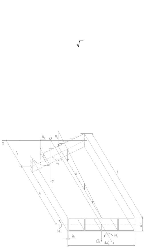
1. Solving system of differential equations. Fig. 1 shows a shell loaded with moments, force and distributed load concentrated at the section z = l
q(z) q0 (1 z / l),
18
Issue № 2(30), 2016 |
|
ISSN 2075-0811 |
where q 0 is the loa d intensity a t z = 0. Th thickness of a wall a d panels c n be assum ed to be a variab le using a ower law
h(z) (b z )k ,
where
b k h1 ,
As ben d warping is relatively small and does not ha ve a great effect on n ormal strain s [5], in
order t o obtain an approximate analyti cal solution a |
bend warping of the contou can be |
|
neglect ed. Let a shell be loaded with a concentrated |
force Q y, bending Мх and rolling Mz |
|
moments at the se tion z = l. In this case |
generalized displace ents Vj an d thus deformations |
|
and strains are ide tified usin the soluti |
n of four differential e quations: |
|
a22V2 b24V 4 Qy , a44V4 a46V6 b47V7 Qy ( z l) M x ,
a66V6 a64V4 b67V7 M z , (a77V7 ) b47V4 b67 V6 c77V7 0,
where a ij, bij, cij ar e variable coefficients. The gener lized displ acement V7 corresponding with rolling warping is expressed using modi fied Bessel Ip, Kp [6] and Struve Λp functions in an identica l fashion [2 ].
Fig. 1
19
Scientific Herald of t he Voronezh State University o f Architecture and Civil Engineering. Construction and Architecture
Using C a prismatic four-c onnected th in-walled structure was calculated in bending by a distributed load q( ) and rollin g concentrated at the section z = l with a rolling moment Mz.
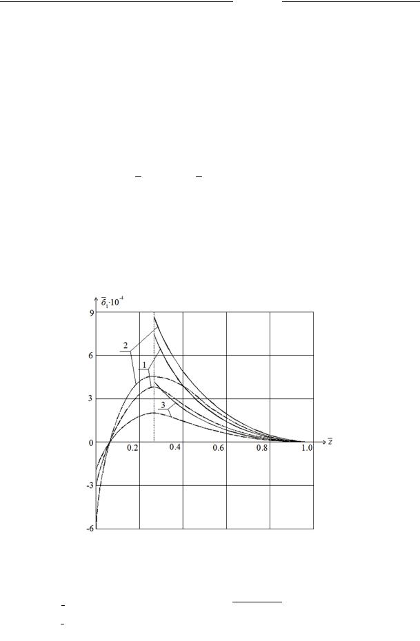
2. Numerical results. Fig. 2 shows depe ndency graphs
1 1 / E f (z ) for line ar load ben ding q(z); it is accepted that
l2 = 0,4 25 m, d2 = 0,16 m,
0 = 56о, q0 = 24,5 kN/m, l = 1,6 m ; the dimensionless p arameters are
d d1 / 4d2 , h h1 / h2 , z z / l .
Сontinu ous curves are designed using a short one and the dotted ones along long ri bs of the upper panel which corresponds to the coo rdinates: x = 2d2, y = –d1/2 и x = –2d2, y = – d1/2. The ana lysis of the graphs in Fig. 2 shows that the distribution σ1 largely depends on h (curves 1 and 2). The relative height of a structure considerably influences its stress and strain (curves 2 and 3).
Fig. 2
Table 1
Curve |
1 |
|
2 |
|
3 |
|
|
|
|
|
|
d |
0,125 |
|
0,125 |
0,25 |
|
|
|
|
|
|
|
h |
1,25 |
|
5 |
|
5 |
|
|
|
|
|
|
20