

Energies 2018, 11, 2463 |
11 of 20 |
4.3.2. Mid-Point Grounding with High Resistance
Compared to a direct grounding system, this method makes protection against electric shock easier and the voltage to grounding is halved. Unlike in direct grounding, this method requires a resistance balancer in order to avoid any difference in ground voltage between positive and negative lines. Also, detecting an accidental current is difficult during faults as the magnitude of the current is small due to the high resistance. Hence, this method has decreased detection accuracy. Similar to mid-point line grounding, both the positive and negative lines have to be disconnected at the same time. In the mid-point high resistance grounding system, as the number of loads increases, the total resistance of the system decreases and the fault current is no longer small. A simple representation of this type of grounding is shown in Figure 6d.
4.3.3. One-End Grounding with High Resistance
This method provides an even easier detection and breaking of fault currents compared to the direct grounding system. Monopole breaking of accidental current is possible as it is a one-end grounding method. However, detecting an accidental current is difficult since the magnitude is small and hence it has decreased detection accuracy. Just like in mid-point high-resistance grounding, the combined resistance decreases as the number of loads increase.
4.3.4. Floating System
In this type of grounding, there is no return path to ground and hence the current received during an electric shock is almost zero. This type of system is not very safe because just like in high-resistance grounding systems, the combined insulation resistance of the system decreases as the number of loads increase. Also, implementing such a system is very expensive as the devices used will require complete isolation. It is difficult to detect an earth fault and the voltage to ground may not be constant.
According to [37], based on its merits; NTT Facilities, France Telecom, and Emerson network power have selected and highly recommend high resistance mid-point grounding for 400 Vdc distribution systems. This method provides better personal safety (by limiting fault currents to harmless levels) compared to other grounding methods for higher DC voltages.
5. Reliability
The reliability of both AC and DC systems depends on their system architecture and the level of redundancies. Especially, in DC systems, increasing the system voltage level adversely affects the electrical stresses experienced by the components (switches, breakers, etc.), thereby reducing the reliability of the system. Switching devices like power MOSFETs, IGBTs, diodes, etc. should always be operated within their safe operating area and, hence, are selected considering enough safety margins to take care of the voltage and current transients.
It has been observed that an increase in bus voltages reduces the life of capacitors [46]. The lifetime of electrolytic capacitors is given by
L = L0 Mv 2 |
( Tcore_max Tcore ) |
. |
(1) |
||
|
10 |
|
|||
|
|
|
|
||
In the above equation, L is the lifetime (hours), L0 is the base lifetime at maximum core temperature (hours), Tcore and Tcore_max are the normal and maximum operating temperatures of the core ( C) respectively, and Mv is the voltage multiplier, which is the ratio of rated voltage to the applied voltage. The life of the capacitors is adversely affected when they are subjected to higher voltage and current stresses, which causes their core temperature to rise, resulting in degradation of their performance. Therefore, it is very important to select suitable capacitors with sufficient voltage ratings. On the other hand, DC systems with higher DC bus voltages would require smaller capacitances because for the same amount of power the capacitance is inversely proportional to the square of voltage. Thus,
Energies 2018, 11, 2463 |
12 of 20 |
the system reliability can be improved by selecting capacitors with sufficient voltage ratings and by also using a series-parallel combination of capacitors.
If batteries are used for energy storage in higher voltage DC systems, then more battery cells
would be required to be connected in series to attain the required voltage. This leads to reduced
Energies 2018, 11, x FOR PEER REVIEW 13 of 21 system reliability as the failure in any one cell in the string of cells would result in the failure of the
whole battery pack. This issue can be addressed by using high-efficiency, high-gain bidirectional
to AC UPS systems. In [48], a static reliability modeling approach was used to compare the reliability power converters and having a reduced number of series battery cells, making the system more
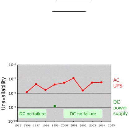
and availability of different AC UPS topologies and 380 Vdc topologies typically used in the telecom reliable. Figure 7 shows the field data collected by NTT facilities of Japan on AC UPS and DC power
andsuppliesdata center[47].applicationsIt can be seen. fromThe reliabilitythe plot hatofDCa systempower supplican bescalculatedare less pronebasedto failureson thecomparedMTBF (Mean TimetobetweenAC UPS systemsFailures). Inand[48],MTTRa static(MerelianbilityTimemodelingto Repair)approachof thewascomponents,used to comparesub-systems,the reliabilityand other
and availability of different AC UPS topologies and 380 Vdc topologies typically used in the telecom |
|
||||||
relevant events. |
|
|
|
|
|
|
|
and data center applications. The reliability of a system can be calculated based on the MTBF (Mean |
|
||||||
relevant events. |
|
|
|
|
|
|
(2) |
= |
MTBF |
|
|
|
|
|
|
Time between Failures) and MTTR (Mean Time to Repair) of the components, sub-systems, and other |
|
||||||
A = |
|
( +) |
(2) |
|
|||
|
|
|
|
|
|
|
|
|
(MTBF + MTTR) |
|
(3) |
||||
|
|
|
|
|
|
|
|
|
|
( + ) |
|
||||
|
|
MTTR |
|
|
|
|
|
U = |
= |
|
|
(3) |
|
||
(MTBF + MTTR) |
|
||||||
|
( ) = |
, , |
|
|
|
(4) |
|
R(t) = e t/MTBF/ |
|
|
(4) |
||||
where, A and U are the availability and unavailability of the system, respectively, and R(t) is the time-
where, A and U are the availability and unavailability of the system, respectively, and R(t) is the dependent reliability function. It has been shown that the reliability and availability of the DC UPS
time-dependent reliability function. It has been shown that the reliability and availability of the DC system is 10 times higher than that of the AC solution.
UPS system is 10 times higher than that of the AC solution.
FigureFigure7. Reliability7. Reliabilityfieldfielddatadataofofpower systemsfor10,000UPSsUPSsandand23,00023,000DCDCsystemssystems(© of(©NTTof NTT
Facilities) [47].
Facilities) [47].
In telecom and data centers, DC distribution systems are more reliable than conventional AC
In telecom and data centers, DC distribution systems are more reliable than conventional AC systems despite the fact that the components experience higher electrical stresses [49]. The reason
systems despite the fact that the components experience higher electrical stresses [49]. The reason behind this higher reliability is the reduction in the number of conversion stages used in these systems.
behindThe authorsthis higherof [24reliability] mention thatis datathe reductioncenters within380Vdcthe numberdistributionof conversionare 1000% morestagesreliableuseddueintothese systemsthe elimination. The authorsof theofextra[24]conversimention stagesthat data. A studycentersperformedwith 380Vdcon applyingdistribution380 Vdc distributionare 1000%tomore reliable5MWduedatato thecenterliminationof Intel JFSIofmodulethe extraC inconversionHillsboro, foundstagesthat. Athestudyreliabilityperformedof the systemon applyingusing 380
380 Vdc were higher compared to an AC tier IV distribution [24].
Vdc distribution to a 5MW data center of Intel JFSI module C in Hillsboro, found that the reliability
of the system using 380 Vdc were higher compared to an AC tier IV distribution [24].
6. Cost
6. Cost DC distribution systems cost less than AC distribution systems. Using higher DC voltage levels
further reduces the system costs and improves the system efficiency, thus reducing the operational costs
DC distribution systems cost less than AC distribution systems. Using higher DC voltage levels of the system. Power electronic converters add up to being a major component of the system cost. The
further reduces the system costs and improves the system efficiency, thus reducing the operational costs of the system. Power electronic converters add up to being a major component of the system cost. The reduction in the number of conversion stages using a high voltage DC system eliminates the need for these converters, which greatly reduces the system costs [50]. Moreover, smaller floor space is required as number of conversion stages are reduced, which further reduces the cost. On the
Energies 2018, 11, 2463 |
13 of 20 |
reduction in the number of conversion stages using a high voltage DC system eliminates the need for these converters, which greatly reduces the system costs [50]. Moreover, smaller floor space is required as number of conversion stages are reduced, which further reduces the cost. On the other hand, higher voltages require elaborate protection schemes with costly fusing, wiring, and non-standard connectors that can offset the cost savings. Furthermore, the component costs can also add up to the overall system costs, for e.g., the system would now require expensive capacitors with higher voltage ratings. Thus, these design factors can cause some offset of the savings.
With an increase in voltage level, the amount of copper required to limit the copper losses
decreases. This is inversely proportional to the square of the voltage. The authors in reference [51]
Energies 2018, 11, x FOR PEER REVIEW 14 of 21 compare the copper cable required for a power transmission of 100 kW in 48 Vdc and 400 Vdc.
They conclude that the 400 Vdc requires 10 times less copper than the 48 Vdc, making it less costly. conclude that the 400 Vdc requires 10 times less copper than the 48 Vdc, making it less costly. Also,
Also, the cabling and installation costs are reduced as the smaller conductors used are more flexible the cabling and installation costs are reduced as the smaller conductors used are more flexible and
and easier to lay. easier to lay.
According to reference [24], a 380 Vdc system, compared to an AC system, requires 15% less
According to reference [24], a 380 Vdc system, compared to an AC system, requires 15% less
initial capital cost due to the reduced power conversion and 33% less floor space, which contributes to initial capital cost due to the reduced power conversion and 33% less floor space, which contributes
the reduced cost; it also has a 36% lower lifetime cost. Conductor costs in distribution systems can be to the reduced cost; it also has a 36% lower lifetime cost. Conductor costs in distribution systems can
10–15% of the total hardware cost and increasing the DC bus voltage level can represent less than 5% be 10–15% of the total hardware cost and increasing the DC bus voltage level can represent less than
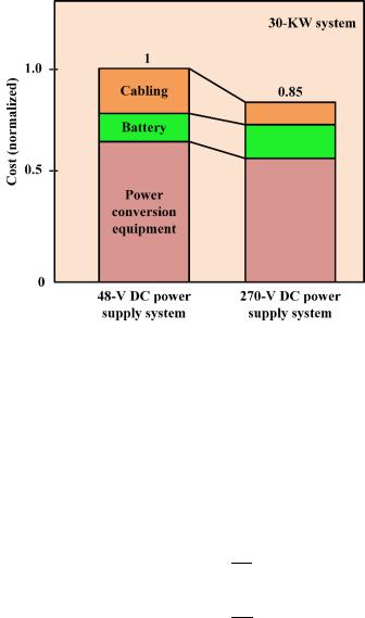
savings in the total hardware costs [31]. In reference [31], it has been shown that the cost of a 270 Vdc
5% savings in the total hardware costs [31]. In reference [31], it has been shown that the cost of a 270
system is 15% lower than that of a 48 Vdc system. The cost breakdown for a 30 kW, 270 Vdc, and a
Vdc system is 15% lower than that of a 48 Vdc system. The cost breakdown for a 30 kW, 270 Vdc, and
48 Vdc system is shown in Figure 8. It is shown that, due to the lower number of conversion stages, a 48 Vdc system is shown in Figure 8. It is shown that, due to the lower number of conversion stages,
the equipment cost is lower for the 270 Vdc system. The cabling cost is also lower compared to a 48 the equipment cost is lower for the 270 Vdc system. The cabling cost is also lower compared to a 48
Vdc systems since smaller diameter wires are used. On the other hand, the battery cost is higher for a
Vdc systems since smaller diameter wires are used. On the other hand, the battery cost is higher for
270 Vdc system since more cells are connected in series. a 270 Vdc system since more cells are connected in series.
Figure 8. Cost breakdown of 48 Vdc and 270 Vdc systems.
Figure 8. Cost breakdown of 48 Vdc and 270 Vdc systems.
7.Voltage Level Selection
7.Voltage Level Selection
The voltage level of DC distribution system should be selected to maximize the system efficiency
The voltage level of DC distribution system should be selected to maximize the system efficiency and reliability, while reducing system costs and increasing the flexibility of the system for future and reliability, while reducing system costs and increasing the flexibility of the system for future expansion. The voltage drop and power loss [52] in a DC line can be calculated using Equations (5) expansion. The voltage drop and power loss [52] in a DC line can be calculated using Equations (5) and (6). According to these equations, with line resistance and power requirement being constant, the and (6). According to these equations, with line resistance and power requirement being constant,
the only way to achieve a smaller voltage drop and power loss is by selecting a higher DC voltage for the distribution.
∆ |
= 2 |
× × |
|
(5) |
|
|
|
|
|
∆ |
= 2 |
× × |
|
(6) |
Energies 2018, 11, 2463 |
14 of 20 |
only way to achieve a smaller voltage drop and power loss is by selecting a higher DC voltage for the distribution.
DVdc = 2 R |
P |
(5) |
||
V |
||||
|
|
dc |
|
|
DPdc = 2 R |
|
P2 |
(6) |
|
Vdc2 |
|
|||
European telecom standard EN41003 and UL 1950 designated 60 Vdc as the maximum SELV (safety extra low voltage) limit [20,21]. For this reason, a nominal voltage of 48 Vdc has been chosen as the best choice for low-voltage distributed power system in conventional data centers and telecommunication systems. However, higher system voltages are preferred for the abovementioned factors, but there are also challenges like system safety and protection that can lead to fire hazards. Furthermore, the system reliability is affected as there is enhanced risk of component failure with the increased voltage and current stresses.
In reference [30], it has been reported that Telecom New Zealand deployed a 220 Vdc system for increased power capacity to replace the existing 50 Vdc system. The installed system has reportedly reduced the installation and copper costs, uses 30–40% smaller batteries, and maximizes available floor space. In reference [35], for a 220 Vac single-phase system or 380 Vac three-phase system, the DC bus voltage is chosen to be 110 Vdc with mid-point grounding. The DC bus voltages are selected such that the existing electric appliances can be used in the proposed system with few or no modifications. In reference [36], (DC)2 ™ concept has been introduced for DC integrated data centers, which have higher system efficiency and reliability compared to conventional AC distribution systems. This concept involves enhancing the operational availability of the data centers with the backup provided by using different distributed energy sources and energy storage systems. The distribution bus voltage of the proposed system is in the range of 500–550 Vdc and has increased system reliability with the integration of the distributed energy sources. Furthermore, it has been reported that the improvement in the system efficiency decreases the power required for the cooling systems, which results in a 21% savings in total energy consumption compared to AC systems.
8. Global Market for DC Distribution Systems
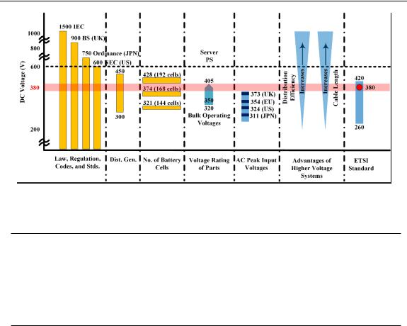
The only existing DC distribution implementations, until the last decade, were telecommunication and data centers operating at 48 Vdc. Research initiatives on high-tech buildings like telecommunication and data centers began in the early 2000s as a result of energy issues in California. The LBNL started looking into the efficiency of power distribution in data centers in 2004. A 380 Vdc distribution system was set up for demonstration in Newark, CA. Later, in its 2008 report, it reported an improvement in efficiency of 28% and 7%, respectively, compared to 208 Vac and 408 Vac systems in data centers [20,24]. By 2009, new facilities with DC distribution were already being implemented and studied globally, with voltage levels varying between 220 Vdc to 550 Vdc. By the end of 2014, there were more facilities implementing DC distribution at a voltage level of 380 Vdc [53–57]. As shown in Figure 9, it can be observed that the telecom and data center industry is converging at 380 Vdc as the voltage level suitable for DC distribution [47,53–56]. As of 2014, several facilities with high voltage DC systems have been established around the globe and are listed in Table 4.
The growing number of demonstration sites and early adopters indicates a growing interest in 380 Vdc distribution. Many industry standard bodies like the European Telecommunications Standard Institute (ETSI), the Alliance for Telecommunications Industry Solutions (ATIS), the International Telecommunications Union (ITU), eMerge Alliance, the International Electrotechnical Commission (IEC), Underwriters Laboratories (UL), and many others have released standards and are currently working on more in 380 Vdc distribution [53–56]. The standards released by 2014 are listed in Table 5. These standards are related to the power supply interface, DC UPS, DC equipment installation and grounding, safety, and component connectors. Currently, more research is underway on standardizing 380 Vdc distribution. Many companies have already released products compatible with 380/400 Vdc
Energies2018,,11,,x2463FOR PEER REVIEW |
1715of 201 |
||
|
|
|
|
|
Connectors |
Anderson, Hubbel, Rong Feng/Delta, Fujitsu Components |
|
distribution into the market. A list of companies providing components for 380 Vdc distribution is |
|
Rack-Mount Power Supply |
Emerson, Delta, AcBel, others |
given inPowerTableComponents6. Many more companies are showing interest inVicor380 Vdc and announcing products for the future. ICT Load HP, IBM, Juniper, NEI, NEC, Supermico
Figure99..DCbusvoltagelevelselection[47]47]..
9. Conclusions Table 4. Global DC distribution systems [53].
DC distribution systems have many inherent advantages over AC distribution like improved |
|||
Year |
Country |
Organization |
Voltage Level |
efficiency and reliability, easier integration of renewable energy sources and energy storage systems, |
|
Intel Corporation |
400 Vdc |
and reduced costs. Moreover, DC systems have no reactive power and frequency stabilization issues, |
||
United States |
University of California, San Diego (UCSD) |
380 Vdc |
which result in reduced copper losses. Many loads likeValidusconsumer(ABB) electronics, light-emitting550 Vdc diode
2009 |
France |
France Telecom |
350 Vdc |
(LED) lighting systems, appliances using variable speed motor drives, etc., require DC power. |
|||
|
Sweden |
UPN AB. |
350 Vdc |
Currently, major applications of DC distribution systems are in the fields of telecommunication |
|||
|
Japan |
NTT group |
380/400 Vdc |
systems, data centers, DC buildings, and microgrids. |
Telecom NZ |
220 Vdc |
|
|
New Zealand |
||
In the current scenario, new facilities are being deployed with DC distribution worldwide due
SAP
to its many advantages. 380 Vdc is the accepted voltage level among all the organizations establishing
Intel Corporation
facilities with DC distribution due to its high efficiency, reliability, and reduced copper costs. The
Stanford University
high efficiency of DC distribution is mainly attributed to the reduced number of power conversion |
|
|
IO |
|
University of California, San Diego (UCSD) |
stages. Furthermore, radial bus structure is more suitable for residential buildings due to the low cost |
|
|
Duke Energy |
and low reliability requirements. In mission-critical facilities like data centers and telecom centers, |
|
United States |
Clustered Systems |
where the reliability requirements are high, a ladder or meshed bus structure is preferred. Mid-point,
NEXTEK
high-resistance grounding has been recommended as the bestIBMgrounding method for DC distribution
|
|
Validus (ABB) |
|
systems as it limits the fault current to harmless levels. |
|
||
|
|
Syracuse University |
380 Vdc |
Various industry standard bodies like ATIS, ETSI, SCTE, eMerge Alliance, ITU-T, IEC, UL, NEC, |
|||
|
|
Steel Ocra |
|
and NEMA have been working on standards relating to 380 Vdc. A few industry standards have |
|||
2014 |
|
North America Telecom |
|
already been established and some are still under development. Many companies like HP, Starline, |
|||
|
Canada |
Canada Telecom Operator |
|
|
France |
France Telecom |
|
GVA Lighting, Emerson, ABB, Schneider, etc., have started providing products used in 380 Vdc |
|||
|
Swiss |
Green.Ch, ABB |
|
systems. With growing market applications and new industry standards under development, 380 |
|||
|
India |
IBM |
|
Vdc is gaining popularity among telecom and data centers. In the future, 380 Vdc might also be used |
|||
|
Taiwan |
Taiwan IT |
|
for residential and commercial buildings on a larger scale. |
|
||
|
Singapore |
IBM |
|
|
China |
China Mobile |
|
Author Contributions:NewSinceZealandthis is a review paper, each TelecauthormwasNZ equally responsible for gathering the
|
Japan |
NTT Group |
380/400 Vdc |
|
information. Each author was assigned with the task of putting together multiple sections. All authors |
||||
|
Norway |
UPN AB |
350/380 Vdc |
|
contributed to the writing, review, and editing of the paper. Supervision and overseeing of the progress of the |
||||
|
Sweden |
Netpower Labs AB |
350/380 Vdc |
|
paper was carried out by V.A.P. |
- |
300/380 Vdc |
||
|
Korea |
|||
Conflicts of Interest: The authorsChina |
declare no conflicts of interestChina. Telecom |
240/380 Vdc |
||
|
|
|
|
|