


Energies 2018, 11, 2463 |
4 of 20 |
It is observed that the higher the reliability requirement, the higher the cost of the system will be. Therefore, the selection of the bus structure is based on how reliable the system must be and how much one is willing to pay for it. For residential applications, where reliability is not a dictating factor, a simple radial bus structure can be implemented. One good example of a radial DC bus structure is the DC nanogrid architecture [16], where the renewable energy sources and storage systems are integrated along with the existing power grid. If an application demands even higher reliability, one can choose from ring, ladder, or meshed bus structures depending on the budget and level of desired reliability. Highly reliable ring, ladder or meshed structures can be seen in telecommunication systems and data centers. A comparison of the advantages and disadvantages of the four DC bus structures discussed in terms of reliability, number of components, and cost is presented in Table 1.
Table 1. Advantages and disadvantages of different DC bus structures.
System Features |
Radial Bus |
Ring Bus |
Ladder Bus |
Meshed Bus |
Power Reliability |
Very Low |
Moderate |
High |
Very High |
No. of Components |
Low |
Moderate |
High |
Very High |
Cost |
Very Low |
Low |
Moderate |
Very High |
|
|
|
|
|
2.2. Power Architectures
In general, power architectures for a DC power system can be classified into centralized and distributed architectures [21,22]. The first DC power system introduced was a centralized architecture. In this system architecture, the power was generated, processed, and controlled in one centralized unit and delivered to loads through a network of power conductors or cables. The simple block diagram representation of a centralized power system architecture is shown in Figure 2a. This type of system architecture is effective if the loads are all of a defined voltage level. As time progressed, the number of loads with different voltage levels increased on the system and eventually, the centralized power architecture could no longer support the needs of the loads. As a result, distributed power system architecture was developed that powered the loads through a number of PECs as shown in Figure 2b.
Energies 2018, 11, x FOR PEER REVIEW |
6 of 21 |
Figure 2. Power architectures: (a) |
(b) distributed. Distribution configuratio s: ( ) parallel; |
|
Figure 2. Power architectures: (a) |
centralized; (b) distributed. |
Distribution configurations: (c) |
(d) cascading; (e) source splitting; (f) load splitting; (g) sum stacking module; (h) difference stacking
parallel; (d) cascading; (e) source splitting; (f) load splitting; (g) sum stacking module; (h) difference module.
stacking module.
3. Efficiency
Efficiency improvement achieved using DC distribution systems compared to AC distribution systems can be attributed to various reasons. The main reason for higher efficiency of DC systems is it requires lower number of power conversion stages. In current architectures, the majority of residential and commercial loads comprise of electronic loads that require DC power. To supply these loads using a conventional AC distribution system, a power electronic converter is required to first convert AC to DC. This power conversion from AC to DC results in additional power losses, usually about 4–15% of the input power; assuming the converters are 85–96% efficient. Therefore, the total
Energies 2018, 11, 2463 |
5 of 20 |
Distributed power system architecture comprises of different PECs, which provide different voltage level outputs catering power to various loads. With ever increasing power demand and loads at different voltage levels, distributed power system architecture gained acceptance, globally replacing the centralized power system architecture. By using smaller PECs, this architecture enables the use of standardized low power modules that make it easy to customize an existing system for any special requirements in the future. PECs can be made more efficient with increased power density by operating at high frequencies, as they are required to handle low power. Higher reliability can be achieved by isolating a fault on one module and keeping the rest of the system unaffected. The various merits of distributed power architecture can be attributed to five basic configurations that are used in order to supply specific loads. They are as follows:
2.2.1. Paralleling
In a paralleling configuration shown in Figure 2c, instead of using a single high power module, multiple low power PEC modules are connected in parallel to supply the load. Since a module processes part of the power, it experiences reduced thermal and electrical stresses, making the overall system more reliable even on increased component count. Individual modules can be reduced in size, cost, and made with a higher power density by operating at higher frequencies. This configuration provides simple maintenance and high reliability using redundancy (using ‘n+1’ modules instead of required ‘n’ modules).
2.2.2. Cascading
In a cascaded configuration shown in Figure 2d, an intermediate bus is introduced into the power conversion of high voltage to a low voltage, which reduces power transformation losses. Also, distribution efficiency is improved when the converter is placed close to the load. The intermediate bus can be used for energy storage integration, improving the reliability and power quality. Cascaded units can be used for different purposes that are difficult to supply by a single converter. An example of such a cascaded configuration is a rectifier cascaded with a DC–DC converter where the rectifier can be used to achieve unity power factor and the DC–DC converter can be utilized for load voltage regulation.
2.2.3. Source Splitting
Source splitting configuration as shown in Figure 2e, enables the use of multiple sources to supply one load. The power redundancy and simple battery backup feature improves the power quality and reliability of this system.
2.2.4. Load Splitting
In load splitting configuration, as shown in Figure 2f, loads are supplied using multiple PECs. This configuration provides better load regulation, which can be difficult to achieve using a single centralized PEC because of the bus impedance. Moreover, this configuration allows selective battery backup for critical loads, which reduces the size and cost of batteries used in the system. Also, as different loads are supplied from separate sources, noise interference is reduced.
2.2.5. Stacking
Stacking configuration of PECs is mainly used to achieve desired output voltage levels by combining the outputs of multiple units. By stacking standardized units, non-standardized outputs can be obtained. For high voltage loads, the outputs of different PECs can be added as shown in Figure 2g. When a smaller voltage than standardized voltage is required, the difference of outputs can be obtained by connecting the outputs as shown in Figure 2h.

Energies 2018, 11, 2463 |
6 of 20 |
3. Efficiency
Efficiency improvement achieved using DC distribution systems compared to AC distribution systems can be attributed to various reasons. The main reason for higher efficiency of DC systems is it requires lower number of power conversion stages. In current architectures, the majority of residential and commercial loads comprise of electronic loads that require DC power. To supply these loads using a conventional AC distribution system, a power electronic converter is required to first convert AC to DC. This power conversion from AC to DC results in additional power losses, usually about 4–15% of the input power; assuming the converters are 85–96% efficient. Therefore, the total system losses become relatively high as the number of power converters increase. Applications using variable speed drives, a washing machine or heating, ventilation, and air conditioning (HVAC) systems for example, require a rectifier for AC to DC conversion and then another converter to generate variable AC. Having a DC system eliminates the use of the rectifier stage thereby improving the system efficiency.
The power conversion road map for AC and DC power systems given in Table 2 [23] shows that DC systems have fewer conversion stages compared to AC systems for DC loads, AC loads, and AC loads with AC converters (ACwC Load).
Table 2. Power conversion roadmap for AC and DC power systems [23].
System |
Source |
DC Load |
AC Load |
ACwC Load |
|
AC |
DC |
DC–AC–DC |
DC–AC |
DC–AC–DC–AC |
|
|
|
|
|
||
AC |
AC–DC |
- |
AC–DC–AC |
||
|
|||||
|
|
|
|
|
|
DC |
DC |
- |
DC–AC |
DC–AC |
|
|
|
|
|
||
AC |
AC–DC |
AC–DC–AC |
AC–DC–AC |
||
|
|||||
|
|
|
|
|
From another point of view, the absence of reactive power and skin effect are other reasons for improved efficiency in a DC distribution system compared to an AC distribution system. Since there is no reactive power in a DC system, the apparent and active powers are equal, which results in reduced losses in the system. In an AC system, skin effect increases the effective resistance of the wires and therefore results in higher distribution losses. Since such an effect is absent in a DC system, it has better efficiency than an AC system.
Various studies have been performed to validate the efficiency improvement in a DC distribution system. Lawrence Berkley national laboratory (LBNL) started investigating the DC distribution efficiency in data centers in 2004. The results obtained in their study stated that DC distribution consumed 28% less power compared to a typical AC distribution in data centers [20,24,25]. In reference [26], 220 Vac distribution was compared to 400 Vdc for power distribution in buildings. It was observed that in switching from AC to DC, an efficiency gain of 17.7%, 9.49%, and 18.9% was achieved in office, residential, and school buildings, respectively. The investigation carried out in [25] concluded that at 50% load, 380 Vdc system was the most efficient among the systems considered for study. The results of this study are shown in Table 3. The author of reference [27] explains that when a distribution system integrated with DC sources (e.g., fuel cells, solar panels, etc.) was considered, a DC distribution system was more efficient than an AC system.
Table 3. Efficiency comparison of five distribution systems at 50% load [25].
System |
Uninterruptible Power Supply |
Distribution |
IT Power Supply |
Overall Efficiency |
|
(UPS) |
|||||
|
|
|
|
||
|
|
|
|
|
|
480 to 208 Vac |
96.20% |
96.52% |
90.00% |
83.56% |
|
400/230 Vac |
96.20% |
99.50% |
90.25% |
86.39% |
|
48 Vdc |
92.86% |
99.50% |
91.54% |
84.58% |
|
380 Vdc |
96.00% |
99.50% |
91.75% |
87.64% |
|
Hybrid 575 Vdc |
95.32% |
92.54% |
91.54% |
80.74% |
|
|
|
|
|
|
Energies 2018, 11, 2463 |
7 of 20 |
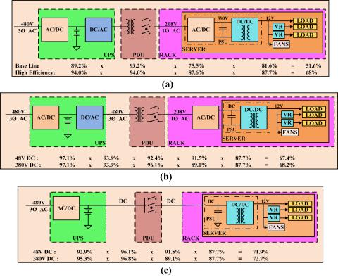
Low voltage DC systems designed for applications such as telecom and datacenters operate at 48 Vdc. At least three conversion stages from the AC input to the load are required to achieve this voltage level, which reduces the system efficiency. In references [28–36], different voltage levels have been proposed for a DC bus based on efficiency, cost, and reliability considerations. In references [3,4], three different power architectures, namely conventional AC architecture, rack-level DC architecture, and facility-level DC architecture, have been described that are commonly utilized in data and telecom centers. Conventional AC system architecture for data center applications, shown in Figure 3a, has several conversion stages that include the double conversion stage of the uninterruptible power supply (UPS). The AC input voltage is first converted to DC, where the energy storage system is connected, and then converted back to AC. In the next stage the voltage is stepped down to 208 Vac using a transformer in the power distribution unit (PDU). This AC voltage is once again converted to a DC voltage in the range of 380–400 Vdc using an AC–DC converter in the power supply unit (PSU). Isolated DC–DC converters are used to step down the voltage to levels suitable for distribution to the loads. For this configuration the overall system efficiency when operated at high load conditions is typically around 50%.
In the rack-level DC configuration presented in Figure 3b, the AC–DC converter is shifted from the PSU of the server to the rack, thus reducing the server cooling requirements. The server volume is also reduced and the whole consolidated rack has higher power density and improved light load efficiency. Compared to the conventional AC architecture, an improvement in the overall system efficiency is not expected since the number of conversion stages are the same.
In the facility-level DC architecture shown in Figure 3c, the DC–AC conversion stage in the UPS, the AC–DC conversion stage in the PSU of the server, and the transformer in the PDU are removed. Therefore, the number of conversion stages are reduced and the power delivery efficiency is
significantly increased. |
8 of 21 |
Energies 2018, 11, x FOR PEER REVIEW |
Figure 3. Power architectures in telecom and data centers: (a) conventional AC architecture;
Figure 3. Power architectures in telecom and data centers: (a) conventional AC architecture; (b) rack-
(b) rack-level DC architecture; (c) facility-level DC architecture [4]. level DC architecture; (c) facility-level DC architecture [4].
In reference [36], a 380 Vdc modified power delivery architecture was proposed for server applications because it is more efficient than the conventional 48 Vdc system. In the modified power delivery architecture, the improvement in efficiency is obtained by reducing the number of power conversion stages and placing isolated DC–DC converters close to the load. Based on the abovementioned references and their claims, one can reach the conclusion that not only is a DC